fuel additives DODGE RAM 2002 Service Repair Manual
[x] Cancel search | Manufacturer: DODGE, Model Year: 2002, Model line: RAM, Model: DODGE RAM 2002Pages: 2255, PDF Size: 62.07 MB
Page 15 of 2255
FLUID TYPES
DESCRIPTION - FUEL REQUIREMENTS - GAS
ENGINES
Your engine is designed to meet all emissions reg-
ulations and provide excellent fuel economy and per-
formance when using high quality unleaded gasoline
having an octane rating of 87. The use of premium
gasoline is not recommended. The use of premium
gasoline will provide no benefit over high quality reg-
ular gasoline, and in some circumstances may result
in poorer performance.
Light spark knock at low engine speeds is not
harmful to your engine. However, continued heavy
spark knock at high speeds can cause damage and
immediate service is required. Engine damage result-
ing from operation with a heavy spark knock may
not be covered by the new vehicle warranty.
Poor quality gasoline can cause problems such as
hard starting, stalling and hesitations. If you experi-
ence these symptoms, try another brand of gasoline
before considering service for the vehicle.
Over 40 auto manufacturers world-wide have
issued and endorsed consistent gasoline specifications
(the Worldwide Fuel Charter, WWFC) to define fuel
properties necessary to deliver enhanced emissions,
performance and durability for your vehicle. We rec-
ommend the use of gasolines that meet the WWFC
specifications if they are available.
REFORMULATED GASOLINE
Many areas of the country require the use of
cleaner burning gasoline referred to as ªreformulat-
edº gasoline. Reformulated gasoline contain oxygen-
ates, and are specifically blended to reduce vehicle
emissions and improve air quality.
We strongly supports the use of reformulated gas-
oline. Properly blended reformulated gasoline will
provide excellent performance and durability for the
engine and fuel system components.
GASOLINE/OXYGENATE BLENDS
Some fuel suppliers blend unleaded gasoline with
oxygenates such as 10% ethanol, MTBE, and ETBE.
Oxygenates are required in some areas of the country
during the winter months to reduce carbon monoxide
emissions. Fuels blended with these oxygenates may
be used in your vehicle.
CAUTION: DO NOT use gasoline containing METH-
ANOL. Gasoline containing methanol may damage
critical fuel system components.
MMT IN GASOLINE
MMT is a manganese-containing metallic additive
that is blended into some gasoline to increase octane.
Gasoline blended with MMT provide no performance
advantage beyond gasoline of the same octane num-
ber without MMT. Gasoline blended with MMT
reduce spark plug life and reduce emission system
performance in some vehicles. We recommend that
gasolines free of MMT be used in your vehicle. The
MMT content of gasoline may not be indicated on the
gasoline pump; therefore, you should ask your gaso-
line retailer whether or not his/her gasoline contains
MMT.
It is even more important to look for gasoline with-
out MMT in Canada because MMT can be used at
levels higher than allowed in the United States.
MMT is prohibited in Federal and California refor-
mulated gasoline.
SULFUR IN GASOLINE
If you live in the northeast United States, your
vehicle may have been designed to meet California
low emission standards with Cleaner-Burning Cali-
fornia reformulated gasoline with low sulfur. If such
fuels are not available in states adopting California
emission standards, your vehicles will operate satis-
factorily on fuels meeting federal specifications, but
emission control system performance may be
adversely affected. Gasoline sold outside of California
is permitted to have higher sulfur levels which may
affect the performance of the vehicle's catalytic con-
verter. This may cause the Malfunction Indicator
Lamp (MIL), Check Engine or Service Engine Soon
light to illuminate. We recommend that you try a dif-
ferent brand of unleaded gasoline having lower sulfur
to determine if the problem is fuel related prior to
returning your vehicle to an authorized dealer for
service.
CAUTION: If the Malfunction Indicator Lamp (MIL),
Check Engine or Service Engine Soon light is flash-
ing, immediate service is required; see on-board
diagnostics system section.
MATERIALS ADDED TO FUEL
All gasoline sold in the United States and Canada
are required to contain effective detergent additives.
Use of additional detergents or other additives is not
needed under normal conditions.
FUEL SYSTEM CAUTIONS
CAUTION: Follow these guidelines to maintain your
vehicle's performance:
0 - 2 LUBRICATION & MAINTENANCEBR/BE
Page 16 of 2255
²The use of leaded gas is prohibited by Federal
law. Using leaded gasoline can impair engine perfor-
mance, damage the emission control system, and
could result in loss of warranty coverage.
²An out-of-tune engine, or certain fuel or ignition
malfunctions, can cause the catalytic converter to
overheat. If you notice a pungent burning odor or
some light smoke, your engine may be out of tune or
malfunctioning and may require immediate service.
Contact your dealer for service assistance.
²When pulling a heavy load or driving a fully
loaded vehicle when the humidity is low and the tem-
perature is high, use a premium unleaded fuel to
help prevent spark knock. If spark knock persists,
lighten the load, or engine piston damage may result.
²The use of fuel additives which are now being
sold as octane enhancers is not recommended. Most
of these products contain high concentrations of
methanol. Fuel system damage or vehicle perfor-
mance problems resulting from the use of such fuels
or additives is not the responsibility of
DaimlerChrysler Corporation and may not be covered
under the new vehicle warranty.
NOTE: Intentional tampering with emissions control
systems can result in civil penalties being assessed
against you.
DESCRIPTION - FUEL REQUIREMENTS -
DIESEL ENGINE
DESCRIPTION
WARNING: Do not use alcohol or gasoline as a fuel
blending agent. They can be unstable under certain
conditions and hazardous or explosive when mixed
with diesel fuel.
Use good quality diesel fuel from a reputable sup-
plier in your Dodge truck. For most year-round ser-
vice, number 2 diesel fuel meeting ASTM
specification D-975 will provide good performance. If
the vehicle is exposed to extreme cold (below 0ÉF/-
18ÉC), or is required to operate at colder-than-normal
conditions for prolonged periods, use climatized No. 2
diesel fuel or dilute the No. 2 diesel fuel with 50%
No. 1 diesel fuel. This will provide better protection
from fuel gelling or wax-plugging of the fuel filters.
Diesel fuel is seldom completely free of water. To
prevent fuel system trouble, including fuel line freez-
ing in winter, drain the accumulated water from the
fuel/water separator using the fuel/water separator
drain provided. If you buy good-quality fuel and fol-
low the cold-weather advice above, fuel conditioners
should not be required in your vehicle. If available in
your area, a high cetane ªpremiumº diesel fuel mayoffer improved cold starting and warm-up perfor-
mance.
DESCRIPTION - ENGINE COOLANT
WARNING: ANTIFREEZE IS AN ETHYLENE GLYCOL
BASE COOLANT AND IS HARMFUL IF SWAL-
LOWED OR INHALED. IF SWALLOWED, DRINK
TWO GLASSES OF WATER AND INDUCE VOMIT-
ING. IF INHALED, MOVE TO FRESH AIR AREA.
SEEK MEDICAL ATTENTION IMMEDIATELY. DO NOT
STORE IN OPEN OR UNMARKED CONTAINERS.
WASH SKIN AND CLOTHING THOROUGHLY AFTER
COMING IN CONTACT WITH ETHYLENE GLYCOL.
KEEP OUT OF REACH OF CHILDREN. DISPOSE OF
GLYCOL BASE COOLANT PROPERLY, CONTACT
YOUR DEALER OR GOVERNMENT AGENCY FOR
LOCATION OF COLLECTION CENTER IN YOUR
AREA. DO NOT OPEN A COOLING SYSTEM WHEN
THE ENGINE IS AT OPERATING TEMPERATURE OR
HOT UNDER PRESSURE, PERSONAL INJURY CAN
RESULT. AVOID RADIATOR COOLING FAN WHEN
ENGINE COMPARTMENT RELATED SERVICE IS
PERFORMED, PERSONAL INJURY CAN RESULT.
CAUTION: Use of Propylene Glycol based coolants
is not recommended, as they provide less freeze
protection and less corrosion protection.
The cooling system is designed around the coolant.
The coolant must accept heat from engine metal, in
the cylinder head area near the exhaust valves and
engine block. Then coolant carries the heat to the
radiator where the tube/fin radiator can transfer the
heat to the air.
The use of aluminum cylinder blocks, cylinder
heads, and water pumps requires special corrosion
protection. MopartAntifreeze/Coolant, 5
Year/100,000 Mile Formula (MS-9769), or the equiva-
lent ethylene glycol base coolant with organic corro-
sion inhibitors (called HOAT, for Hybrid Organic
Additive Technology) is recommended. This coolant
offers the best engine cooling without corrosion when
mixed with 50% Ethylene Glycol and 50% distilled
water to obtain a freeze point of -37ÉC (-35ÉF). If it
loses color or becomes contaminated, drain, flush,
and replace with fresh properly mixed coolant solu-
tion.
CAUTION: MoparTAntifreeze/Coolant, 5
Year/100,000 Mile Formula (MS-9769) may not be
mixed with any other type of antifreeze. Mixing of
coolants other than specified (non-HOAT or other
HOAT), may result in engine damage that may not
be covered under the new vehicle warranty, and
decreased corrosion protection.
BR/BELUBRICATION & MAINTENANCE 0 - 3
FLUID TYPES (Continued)
Page 17 of 2255
COOLANT PERFORMANCE
The required ethylene-glycol (antifreeze) and water
mixture depends upon climate and vehicle operating
conditions. The coolant performance of various mix-
tures follows:
Pure Water-Water can absorb more heat than a
mixture of water and ethylene-glycol. This is for pur-
pose of heat transfer only. Water also freezes at a
higher temperature and allows corrosion.
100 percent Ethylene-Glycol-The corrosion
inhibiting additives in ethylene-glycol need the pres-
ence of water to dissolve. Without water, additives
form deposits in system. These act as insulation
causing temperature to rise to as high as 149ÉC
(300ÉF). This temperature is hot enough to melt plas-
tic and soften solder. The increased temperature can
result in engine detonation. In addition, 100 percent
ethylene-glycol freezes at -22ÉC (-8ÉF).
50/50 Ethylene-Glycol and Water-Is the recom-
mended mixture, it provides protection against freez-
ing to -37ÉC (-34ÉF). The antifreeze concentration
must alwaysbe a minimum of 44 percent, year-
round in all climates. If percentage is lower, engine
parts may be eroded by cavitation. Maximum protec-
tion against freezing is provided with a 68 percent
antifreeze concentration, which prevents freezing
down to -67.7ÉC (-90ÉF). A higher percentage will
freeze at a warmer temperature. Also, a higher per-
centage of antifreeze can cause the engine to over-
heat because specific heat of antifreeze is lower than
that of water.
CAUTION: Richer antifreeze mixtures cannot be
measured with normal field equipment and can
cause problems associated with 100 percent ethyl-
ene-glycol.
COOLANT SELECTION AND ADDITIVES
NOTE: Refer to the vehicle's coolant bottle to iden-
tify HOAT or Non-HOAT coolant. Non-HOAT coolant
is green in color.
The use of aluminum cylinder blocks, cylinder
heads and water pumps requires special corrosion
protection. Only MopartAntifreeze/Coolant, 5
Year/100,000 Mile Formula (glycol base coolant with
corrosion inhibitors called HOAT, for Hybrid Organic
Additive Technology) is recommended. This coolant
offers the best engine cooling without corrosion when
mixed with 50% distilled water to obtain to obtain a
freeze point of -37ÉC (-35ÉF). If it loses color or
becomes contaminated, drain, flush, and replace with
fresh properly mixed coolant solution.CAUTION: Do not use coolant additives that are
claimed to improve engine cooling.
DESCRIPTIONÐENGINE OIL
API SERVICE GRADE CERTIFIED
WARNING: NEW OR USED ENGINE OIL CAN BE
IRRITATING TO THE SKIN. AVOID PROLONGED OR
REPEATED SKIN CONTACT WITH ENGINE OIL.
CONTAMINANTS IN USED ENGINE OIL, CAUSED BY
INTERNAL COMBUSTION, CAN BE HAZARDOUS TO
YOUR HEALTH. THOROUGHLY WASH EXPOSED
SKIN WITH SOAP AND WATER. DO NOT WASH
SKIN WITH GASOLINE, DIESEL FUEL, THINNER, OR
SOLVENTS, HEALTH PROBLEMS CAN RESULT. DO
NOT POLLUTE, DISPOSE OF USED ENGINE OIL
PROPERLY. CONTACT YOUR DEALER OR GOVERN-
MENT AGENCY FOR LOCATION OF COLLECTION
CENTER IN YOUR AREA.
Standard engine-oil identification notations have
been adopted to aid in the proper selection of engine
oil. The identifying notations are located on the label
of engine oil plastic bottles and the top of engine oil
cans.
In diesel engines, use an engine oil that conforms
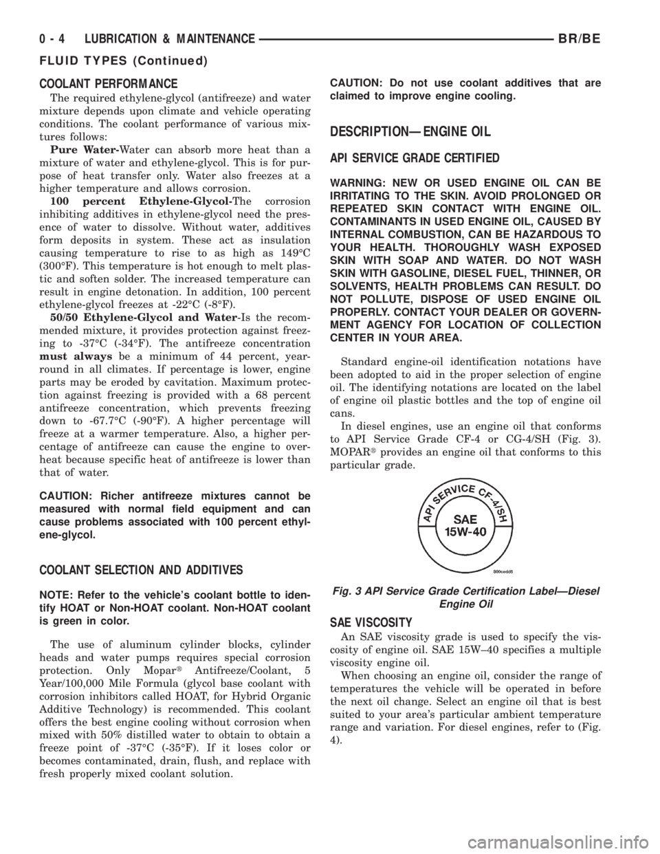
to API Service Grade CF-4 or CG-4/SH (Fig. 3).
MOPARtprovides an engine oil that conforms to this
particular grade.
SAE VISCOSITY
An SAE viscosity grade is used to specify the vis-
cosity of engine oil. SAE 15W±40 specifies a multiple
viscosity engine oil.
When choosing an engine oil, consider the range of
temperatures the vehicle will be operated in before
the next oil change. Select an engine oil that is best
suited to your area's particular ambient temperature
range and variation. For diesel engines, refer to (Fig.
4).
Fig. 3 API Service Grade Certification LabelÐDiesel
Engine Oil
0 - 4 LUBRICATION & MAINTENANCEBR/BE
FLUID TYPES (Continued)
Page 19 of 2255
DESCRIPTION - AUTOMATIC TRANSMISSION
FLUID
NOTE: Refer to the maintenance schedules in this
group for the recommended maintenance (fluid/filter
change) intervals for this transmission.
NOTE: Refer to Service Procedures in this group for
fluid level checking procedures.
MopartATF +4, type 9602, Automatic Transmis-
sion Fluid is the recommended fluid for
DaimlerChrysler automatic transmissions.
Dexron II fluid IS NOT recommended. Clutch
chatter can result from the use of improper
fluid.
MopartATF +4, type 9602, Automatic Transmis-
sion Fluid when new is red in color. The ATF is dyed
red so it can be identified from other fluids used in
the vehicle such as engine oil or antifreeze. The red
color is not permanent and is not an indicator of fluid
condition. As the vehicle is driven, the ATF will begin
to look darker in color and may eventually become
brown.This is normal.A dark brown/black fluid
accompanied with a burnt odor and/or deterioration
in shift quality may indicate fluid deterioration or
transmission component failure.
FLUID ADDITIVES
DaimlerChrysler strongly recommends against the
addition of any fluids to the transmission, other than
those automatic transmission fluids listed above.
Exceptions to this policy are the use of special dyes
to aid in detecting fluid leaks.
Various ªspecialº additives and supplements exist
that claim to improve shift feel and/or quality. These
additives and others also claim to improve converter
clutch operation and inhibit overheating, oxidation,
varnish, and sludge. These claims have not been sup-
ported to the satisfaction of DaimlerChrysler and
these additivesmust not be used.The use of trans-
mission ªsealersº should also be avoided, since they
may adversely affect the integrity of transmission
seals.
OPERATION - AUTOMATIC TRANSMISSION
FLUID
The automatic transmission fluid is selected based
upon several qualities. The fluid must provide a high
level of protection for the internal components by
providing a lubricating film between adjacent metal
components. The fluid must also be thermally stable
so that it can maintain a consistent viscosity through
a large temperature range. If the viscosity stays con-
stant through the temperature range of operation,transmission operation and shift feel will remain con-
sistent. Transmission fluid must also be a good con-
ductor of heat. The fluid must absorb heat from the
internal transmission components and transfer that
heat to the transmission case.
FLUID CAPACITIES
SPECIFICATIONS
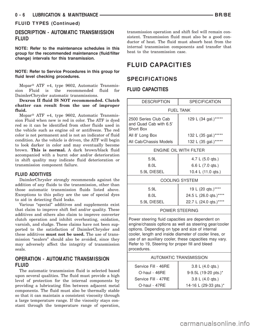
FLUID CAPACITIES
DESCRIPTION SPECIFICATION
FUEL TANK
2500 Series Club Cab
and Quad Cab with 6.5'
Short Box129 L (34 gal.)*****
All 8' Long Box 132 L (35 gal.)*****
All Cab/Chassis Models 132 L (35 gal.)*****
ENGINE OIL WITH FILTER
5.9L 4.7 L (5.0 qts.)
8.0L 6.6 L (7.0 qts.)
5.9L DIESEL 10.4 L (11.0 qts.)
COOLING SYSTEM
5.9L 19 L (20 qts.)****
8.0L 24.5 L (26.0 qts.)****
5.9L DIESEL 22.7 L (24.0 qts.)****
POWER STEERING
Power steering fluid capacities are dependent on
engine/chassis options as well as steering gear/cooler
options. Depending on type and size of internal
cooler, length and inside diameter of cooler lines, or
use of an auxiliary cooler, these capacities may vary.
Refer to 19, Steering for proper fill and bleed
procedures.
AUTOMATIC TRANSMISSION
Service Fill - 46RE 3.8 L (4.0 qts.)
O-haul - 46RE 9-9.5L (19-20 pts.)*
Service Fill - 47RE 3.8 L (4.0 qts.)
O-haul - 47RE 14-16 L (29-33 pts.)*
0 - 6 LUBRICATION & MAINTENANCEBR/BE
FLUID TYPES (Continued)
Page 475 of 2255
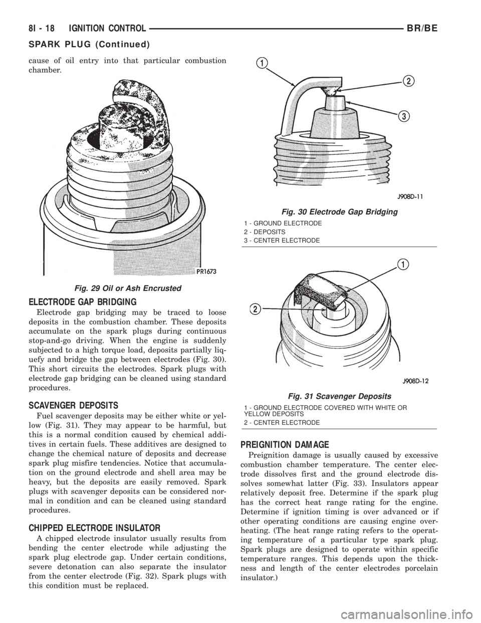
cause of oil entry into that particular combustion
chamber.
ELECTRODE GAP BRIDGING
Electrode gap bridging may be traced to loose
deposits in the combustion chamber. These deposits
accumulate on the spark plugs during continuous
stop-and-go driving. When the engine is suddenly
subjected to a high torque load, deposits partially liq-
uefy and bridge the gap between electrodes (Fig. 30).
This short circuits the electrodes. Spark plugs with
electrode gap bridging can be cleaned using standard
procedures.
SCAVENGER DEPOSITS
Fuel scavenger deposits may be either white or yel-
low (Fig. 31). They may appear to be harmful, but
this is a normal condition caused by chemical addi-
tives in certain fuels. These additives are designed to
change the chemical nature of deposits and decrease
spark plug misfire tendencies. Notice that accumula-
tion on the ground electrode and shell area may be
heavy, but the deposits are easily removed. Spark
plugs with scavenger deposits can be considered nor-
mal in condition and can be cleaned using standard
procedures.
CHIPPED ELECTRODE INSULATOR
A chipped electrode insulator usually results from
bending the center electrode while adjusting the
spark plug electrode gap. Under certain conditions,
severe detonation can also separate the insulator
from the center electrode (Fig. 32). Spark plugs with
this condition must be replaced.
PREIGNITION DAMAGE
Preignition damage is usually caused by excessive
combustion chamber temperature. The center elec-
trode dissolves first and the ground electrode dis-
solves somewhat latter (Fig. 33). Insulators appear
relatively deposit free. Determine if the spark plug
has the correct heat range rating for the engine.
Determine if ignition timing is over advanced or if
other operating conditions are causing engine over-
heating. (The heat range rating refers to the operat-
ing temperature of a particular type spark plug.
Spark plugs are designed to operate within specific
temperature ranges. This depends upon the thick-
ness and length of the center electrodes porcelain
insulator.)
Fig. 29 Oil or Ash Encrusted
Fig. 30 Electrode Gap Bridging
1 - GROUND ELECTRODE
2 - DEPOSITS
3 - CENTER ELECTRODE
Fig. 31 Scavenger Deposits
1 - GROUND ELECTRODE COVERED WITH WHITE OR
YELLOW DEPOSITS
2 - CENTER ELECTRODE
8I - 18 IGNITION CONTROLBR/BE
SPARK PLUG (Continued)
Page 2218 of 2255
ABS - DESCRIPTION, BRAKES...........5-35
ABS - OPERATION, BRAKES.............5-36
ABS BRAKE SYSTEM - STANDARD
PROCEDURE, BLEEDING................5-36
ABS INDICATOR - DESCRIPTION.........8J-14
ABS INDICATOR - OPERATION..........8J-14
A/C APPLICATION TABLE,
SPECIFICATIONS......................24-7
A/C COMPRESSOR - DESCRIPTION......24-46
A/C COMPRESSOR - DIAGNOSIS AND
TESTING...........................24-47
A/C COMPRESSOR - INSTALLATION......24-48
A/C COMPRESSOR - OPERATION........24-46
A/C COMPRESSOR - REMOVAL.........24-47
A/C COMPRESSOR CLUTCH -
DESCRIPTION.......................24-11
A/C COMPRESSOR CLUTCH -
INSPECTION........................24-15
A/C COMPRESSOR CLUTCH -
INSTALLATION.......................24-15
A/C COMPRESSOR CLUTCH -
OPERATION.........................24-13
A/C COMPRESSOR CLUTCH - REMOVAL . . 24-13
A/C COMPRESSOR CLUTCH BREAK-IN -
STANDARD PROCEDURE...............24-13
A/C COMPRESSOR CLUTCH COIL -
DIAGNOSIS AND TESTING.............24-13
A/C COMPRESSOR CLUTCH RELAY -
DESCRIPTION.......................24-17
A/C COMPRESSOR CLUTCH RELAY -
DIAGNOSIS AND TESTING...............24-17
A/C COMPRESSOR CLUTCH RELAY -
INSTALLATION.......................24-18
A/C COMPRESSOR CLUTCH RELAY -
OPERATION.........................24-17
A/C COMPRESSOR CLUTCH RELAY -
REMOVAL..........................24-18
A/C CONDENSER - DESCRIPTION........24-49
A/C CONDENSER - INSTALLATION.......24-50
A/C CONDENSER - OPERATION..........24-49
A/C CONDENSER - REMOVAL...........24-49
A/C EVAPORATOR - DESCRIPTION.......24-53
A/C EVAPORATOR - INSTALLATION......24-53
A/C EVAPORATOR - OPERATION.........24-53
A/C EVAPORATOR - REMOVAL..........24-53
A/C HEATER CONTROL - DIAGNOSIS
AND TESTING.......................24-18
A/C HIGH PRESSURE SWITCH -
DESCRIPTION.......................24-20
A/C HIGH PRESSURE SWITCH -
DIAGNOSIS AND TESTING.............24-20
A/C HIGH PRESSURE SWITCH -
INSTALLATION.......................24-20
A/C HIGH PRESSURE SWITCH -
OPERATION.........................24-20
A/C HIGH PRESSURE SWITCH -
REMOVAL..........................24-20
A/C LINE COUPLERS - DESCRIPTION.....24-40
A/C LINE COUPLERS - OPERATION......24-41
A/C LINE COUPLERS - STANDARD
PROCEDURE........................24-44
A/C LOW PRESSURE SWITCH -
DESCRIPTION.......................24-21
A/C LOW PRESSURE SWITCH -
DIAGNOSIS AND TESTING.............24-21
A/C LOW PRESSURE SWITCH -
INSTALLATION.......................24-21
A/C LOW PRESSURE SWITCH -
OPERATION
.........................24-21
A/C LOW PRESSURE SWITCH -
REMOVAL
..........................24-21
A/C ORIFICE TUBE - DESCRIPTION
.......24-54
A/C ORIFICE TUBE - INSTALLATION
......24-54
A/C ORIFICE TUBE - OPERATION
........24-54
A/C ORIFICE TUBE - REMOVAL
..........24-54
A/C PERFORMANCE - DIAGNOSIS AND
TESTING
............................24-2
ACCELERATOR PEDAL - INSTALLATION
. . . 14-37
ACCELERATOR PEDAL - REMOVAL
.......14-36
ACCELERATOR PEDAL POSITION
SENSOR - DESCRIPTION
...............14-95
ACCELERATOR PEDAL POSITION
SENSOR - INSTALLATION
..............14-97
ACCELERATOR PEDAL POSITION
SENSOR - OPERATION
................14-95
ACCELERATOR PEDAL POSITION
SENSOR - REMOVAL
..................14-95ACCESSORY DRIVE BELT - DIAGNOSIS
AND TESTING................7-24,7-27,7-30
ACCUMULATOR - DESCRIPTION.........24-55
ACCUMULATOR - DESCRIPTION . . 21-149,21-319
ACCUMULATOR - INSPECTION . . . 21-150,21-320
ACCUMULATOR - INSTALLATION........24-55
ACCUMULATOR - OPERATION..........24-55
ACCUMULATOR - OPERATION....21-150,21-320
ACCUMULATOR - REMOVAL............24-55
A/C-HEATER CONTROL - DESCRIPTION . . . 24-18
A/C-HEATER CONTROL - INSTALLATION . . . 24-19
A/C-HEATER CONTROL - OPERATION.....24-18
A/C-HEATER CONTROL - REMOVAL......24-19
ACTUATION TEST MODE - DESCRIPTION,
CIRCUIT.............................25-2
ACTUATOR - INSTALLATION, BLEND
DOOR.............................24-25
ACTUATOR - INSTALLATION, HEAT/
DEFROST DOOR.....................24-27
ACTUATOR - INSTALLATION, INSIDE
HANDLE.......................23-72,23-80
ACTUATOR - INSTALLATION, PANEL/
DEFROST DOOR.....................24-27
ACTUATOR - INSTALLATION,
RECIRCULATION DOOR................24-28
ACTUATOR - REMOVAL, BLEND DOOR....24-25
ACTUATOR - REMOVAL, HEAT/DEFROST
DOOR.............................24-26
ACTUATOR - REMOVAL, INSIDE HANDLE . 23-72,
23-80
ACTUATOR - REMOVAL, PANEL/DEFROST
DOOR.............................24-26
ACTUATOR - REMOVAL, RECIRCULATION
DOOR.............................24-27
ADAPTER - INSTALLATION, DEFROSTER
AND DEMISTER DUCT.................24-33
ADAPTER - REMOVAL, DEFROSTER AND
DEMISTER DUCT.....................24-33
ADAPTER BRACKET - INSTALLATION,
CAB CHASSIS.......................13-10
ADAPTER BRACKET - REMOVAL, CAB
CHASSIS...........................13-10
ADAPTER HOUSING SEAL - NV4500 -
INSTALLATION.......................21-42
ADAPTER HOUSING SEAL - NV4500 -
REMOVAL..........................21-42
ADAPTER HOUSING SEAL - NV5600 -
INSTALLATION.......................21-85
ADAPTER HOUSING SEAL - NV5600 -
REMOVAL..........................21-85
ADDING ADDITIONAL COOLANT -
STANDARD PROCEDURE................7-16
ADDITIONAL COOLANT - STANDARD
PROCEDURE, ADDING..................7-16
ADDITIVES - STANDARD PROCEDURE,
COOLANT SELECTION..................7-17
ADHESIVE LOCATIONS, SPECIFICATIONS
- STRUCTURAL......................23-44
ADJUSTER - INSTALLATION, SEAT BELT
TURNING LOOP.....................8O-29
ADJUSTER - INSTALLATION, SEAT
TRACK............................23-143
ADJUSTER - REMOVAL, SEAT BELT
TURNING LOOP.....................8O-29
ADJUSTER - REMOVAL, SEAT TRACK....23-143
ADJUSTER ASSEMBLY - INSTALLATION,
ROCKER ARM........................9-26
ADJUSTER ASSEMBLY - REMOVAL,
ROCKER ARM........................9-26
ADJUSTER ASSY - CLEANING, ROCKER
ARM ..............................9-146
ADJUSTER ASSY - DESCRIPTION,
ROCKER ARM.......................9-145
ADJUSTER ASSY - INSPECTION,
ROCKER ARM.......................9-146
ADJUSTER ASSY - INSTALLATION,
ROCKER ARM...................9-148,9-84
ADJUSTER ASSY - REMOVAL, ROCKER
ARM ..........................9-145,9-84
ADJUSTER KNOB - INSTALLATION,
TURNING LOOP HGT
.................8O-30
ADJUSTER KNOB - REMOVAL, TURNING
LOOP HGT
..........................8O-30
ADJUSTMENT - STANDARD
PROCEDURE, COMPASS VARIATION
......8M-4
ADJUSTMENT, ADJUSTMENTS
. . . 23-101,23-102,
23-103
ADJUSTMENT, ADJUSTMENTS
...........5-30ADJUSTMENT, ADJUSTMENTS...........13-2
ADJUSTMENT, ADJUSTMENTS . . . 21-208,21-380
ADJUSTMENT AND VERIFICATION -
STANDARD PROCEDURE, VALVE LASH....9-141
ADJUSTMENT, BANDS..........21-151,21-321
ADJUSTMENT, CARGO DOOR...........23-78
ADJUSTMENT, CENTER BEARING..........3-8
ADJUSTMENT, FRONT DOOR FORE/AFT . . . 23-69
ADJUSTMENT, FRONT DOOR IN/OUT.....23-70
ADJUSTMENT, FRONT DOOR LATCH......23-73
ADJUSTMENT, FRONT DOOR UP/DOWN . . . 23-70
ADJUSTMENT, PARKING BRAKE SHOES....5-33
ADJUSTMENT, SHIFT LEVER.....21-463,21-500
ADJUSTMENTS - ADJUSTMENT . . 23-101,23-102,
23-103
ADJUSTMENTS - ADJUSTMENT..........5-30
ADJUSTMENTS - ADJUSTMENT..........13-2
ADJUSTMENTS - ADJUSTMENT . . 21-208,21-380
ADJUSTMENTS, FOG LAMP UNIT........8L-13
ADJUSTMENTS, FRONT AXLE - 248FBI....3-19
ADJUSTMENTS, GEAR.................19-18
ADJUSTMENTS, HEADLAMP UNIT.......8L-21
ADJUSTMENTS, REAR AXLE - 248RBI.....3-51
ADJUSTMENTS, REAR AXLE - 267RBI.....3-83
ADJUSTMENTS, REAR AXLE - 286RBI....3-112
ADJUSTMENTS, TRANSMISSION
THROTTLE VALVE CABLE.........21-210,21-382
ADJUSTMENTS, VALVE BODY....21-257,21-428
AIR BLEED - STANDARD PROCEDURE....14-61
AIR CLEANER ELEMENT - INSTALLATION . . 9-130
AIR CLEANER ELEMENT - REMOVAL.....9-129
AIR CONDITIONER - DESCRIPTION,
HEATER .............................24-1
AIR CONDITIONER - OPERATION,
HEATER .............................24-1
AIR CONDITIONING - INSTALLATION,
WATER PUMP BYPASS HOSE WITH.......7-76
AIR CONDITIONING - INSTALLATION,
WATER PUMP BYPASS HOSE
WITHOUT............................7-77
AIR CONDITIONING - REMOVAL, WATER
PUMP BYPASS HOSE WITH.............7-73
AIR CONDITIONING - REMOVAL, WATER
PUMP BYPASS HOSE WITHOUT..........7-76
AIR CONTROL MOTOR - DESCRIPTION,
IDLE...............................14-40
AIR CONTROL MOTOR - OPERATION,
IDLE...............................14-40
AIR COOLER AND PLUMBING -
CLEANING, CHARGE..................11-19
AIR COOLER AND PLUMBING -
DESCRIPTION, CHARGE...............11-18
AIR COOLER AND PLUMBING -
INSPECTION, CHARGE.................11-19
AIR COOLER AND PLUMBING -
INSTALLATION, CHARGE...............11-20
AIR COOLER AND PLUMBING -
OPERATION, CHARGE.................11-18
AIR COOLER AND PLUMBING -
REMOVAL, CHARGE..................11-18
AIR COOLER SYSTEM - LEAKS -
DIAGNOSIS AND TESTING, CHARGE......11-18
AIR DAM - INSTALLATION, FRONT........13-2
AIR DAM - REMOVAL, FRONT...........13-2
AIR EXHAUSTER - INSTALLATION.......23-77
AIR EXHAUSTER - REMOVAL...........23-77
AIR HEATER - DESCRIPTION, INTAKE....14-104
AIR HEATER - INSTALLATION, INTAKE . . . 14-105
AIR HEATER - OPERATION, INTAKE.....14-104
AIR HEATER - REMOVAL, INTAKE.......14-104
AIR HEATER RELAY - DESCRIPTION,
INTAKE............................14-105
AIR HEATER RELAY - INSTALLATION,
INTAKE............................14-106
AIR HEATER RELAY - OPERATION,
INTAKE............................14-105
AIR HEATER RELAY - REMOVAL, INTAKE . 14-106
AIR IN FUEL SYSTEM - DIAGNOSIS AND
TESTING...........................14-60
AIR INJECTION PUMP - DESCRIPTION....25-29
AIR INJECTION PUMP - DIAGNOSIS AND
TESTING...........................25-29
AIR INJECTION PUMP - INSTALLATION . . . 25-30
AIR INJECTION PUMP - OPERATION
.....25-29
AIR INJECTION PUMP - REMOVAL
.......25-30
AIR INJECTION SYSTEM - DESCRIPTION
. . 25-26
AIR INJECTION SYSTEM - OPERATION
....25-28
AIR INJECTION SYSTEM - TORQUE
......25-29
BR/BEINDEX 1
Description Group-Page Description Group-Page Description Group-Page
Page 2244 of 2255
SEALERS - STANDARD PROCEDURE,
FORM-IN-PLACE GASKETS.....9-10,9-122,9-66
SEALS - INSTALLATION, AXLE SHAFT.....3-31
SEALS - REMOVAL, AXLE SHAFT.........3-31
SEALS - REMOVAL, VALVE STEM.........9-82
SEAT - BENCH SEAT - INSTALLATION....23-133
SEAT - BENCH SEAT - REMOVAL.......23-133
SEAT - INSTALLATION, REAR..........23-144
SEAT - INSTALLATION, SEAT - BENCH . . . 23-133
SEAT - INSTALLATION, SEAT BACK -
BENCH............................23-135
SEAT - REMOVAL, REAR..............23-144
SEAT - REMOVAL, SEAT - BENCH.......23-133
SEAT - REMOVAL, SEAT BACK - BENCH . . 23-135
SEAT - SPLIT BENCH - INSTALLATION . . . 23-134
SEAT - SPLIT BENCH - REMOVAL.......23-133
SEAT ARMREST/CONSOLE -
INSTALLATION, CENTER..............23-132
SEAT ARMREST/CONSOLE - REMOVAL,
CENTER...........................23-132
SEAT ARMREST/LATCH COVER -
INSTALLATION, CENTER..............23-132
SEAT ARMREST/LATCH COVER -
REMOVAL, CENTER..................23-132
SEAT BACK - BENCH SEAT -
INSTALLATION......................23-135
SEAT BACK - BENCH SEAT - REMOVAL . . 23-135
SEAT BACK - SPLIT BENCH -
INSTALLATION......................23-136
SEAT BACK - SPLIT BENCH - REMOVAL . . 23-135
SEAT BACK COVER - INSTALLATION.....23-137
SEAT BACK COVER - REMOVAL........23-137
SEAT BACK COVER - SPLIT BENCH -
INSTALLATION......................23-137
SEAT BACK COVER - SPLIT BENCH -
REMOVAL.........................23-137
SEAT BACK RECLINER - INSTALLATION . . 23-138
SEAT BACK RECLINER - REMOVAL......23-138
SEAT BELT & RETRACTOR -
INSTALLATION, REAR.................8O-26
SEAT BELT & RETRACTOR - REMOVAL,
REAR..............................8O-26
SEAT BELT BUCKLE - INSTALLATION,
FRONT.............................8O-20
SEAT BELT BUCKLE - INSTALLATION,
REAR..............................8O-27
SEAT BELT BUCKLE - REMOVAL, FRONT . . 8O-20
SEAT BELT BUCKLE - REMOVAL, REAR . . . 8O-27
SEAT BELT SWITCH - DESCRIPTION.....8O-28
SEAT BELT SWITCH - DIAGNOSIS AND
TESTING...........................8O-28
SEAT BELT SWITCH - OPERATION.......8O-28
SEAT BELT TURNING LOOP ADJUSTER -
INSTALLATION......................8O-29
SEAT BELT TURNING LOOP ADJUSTER -
REMOVAL..........................8O-29
SEAT CUSHION - INSTALLATION........23-138
SEAT CUSHION - REMOVAL...........23-138
SEAT CUSHION COVER - INSTALLATION . 23-139
SEAT CUSHION COVER - REMOVAL.....23-139
SEAT CUSHION COVER - SPLIT BENCH -
INSTALLATION......................23-140
SEAT CUSHION COVER - SPLIT BENCH -
REMOVAL.........................23-139
SEAT ELEMENT - DESCRIPTION, HEATED . 8G-10
SEAT ELEMENT - INSTALLATION,
HEATED............................8G-13
SEAT ELEMENT - OPERATION, HEATED . . . 8G-11
SEAT ELEMENT - REMOVAL, HEATED....8G-13
SEAT ELEMENT AND SENSOR -
DIAGNOSIS AND TESTING, HEATED......8G-11
SEAT HEATER SWITCH - DESCRIPTION,
DRIVER.............................8G-7
SEAT HEATER SWITCH - DESCRIPTION,
PASSENGER........................8G-16
SEAT HEATER SWITCH - INSTALLATION,
DRIVER............................8G-10
SEAT HEATER SWITCH - INSTALLATION,
PASSENGER........................8G-19
SEAT HEATER SWITCH - OPERATION,
DRIVER
.............................8G-8
SEAT HEATER SWITCH - OPERATION,
PASSENGER
........................8G-17
SEAT HEATER SWITCH - REMOVAL,
DRIVER
.............................8G-9
SEAT HEATER SWITCH - REMOVAL,
PASSENGER
........................8G-18
SEAT MODULE - DESCRIPTION, HEATED
. . 8E-20SEAT MODULE - DIAGNOSIS AND
TESTING, HEATED....................8E-21
SEAT MODULE - INSTALLATION, HEATED . . 8E-23
SEAT MODULE - OPERATION, HEATED....8E-20
SEAT MODULE - REMOVAL, HEATED.....8E-23
SEAT RELAY - DESCRIPTION, HEATED....8G-14
SEAT RELAY - DIAGNOSIS AND
TESTING, HEATED....................8G-15
SEAT RELAY - INSTALLATION, HEATED . . . 8G-16
SEAT RELAY - OPERATION, HEATED.....8G-15
SEAT RELAY - REMOVAL, HEATED.......8G-16
SEAT RISER - INSTALLATION..........23-141
SEAT RISER - REMOVAL..............23-141
SEAT SWITCH - DESCRIPTION, DRIVER
POWER............................8N-17
SEAT SWITCH - DESCRIPTION,
PASSENGER POWER..................8N-20
SEAT SWITCH - DIAGNOSIS AND
TESTING, DRIVER POWER.............8N-17
SEAT SWITCH - DIAGNOSIS AND
TESTING, HEATED...............8G-17,8G-8
SEAT SWITCH - DIAGNOSIS AND
TESTING, PASSENGER POWER.........8N-20
SEAT SWITCH - INSTALLATION, DRIVER
POWER............................8N-18
SEAT SWITCH - INSTALLATION,
PASSENGER POWER..................8N-21
SEAT SWITCH - OPERATION, DRIVER
POWER............................8N-17
SEAT SWITCH - OPERATION,
PASSENGER POWER...................8N-20
SEAT SWITCH - REMOVAL, DRIVER
POWER............................8N-18
SEAT SWITCH - REMOVAL, PASSENGER
POWER............................8N-21
SEAT SYSTEM - DESCRIPTION, HEATED . . . 8G-5
SEAT SYSTEM - DESCRIPTION, POWER . . 8N-16
SEAT SYSTEM - DIAGNOSIS AND
TESTING, HEATED.....................8G-6
SEAT SYSTEM - DIAGNOSIS AND
TESTING, POWER....................8N-16
SEAT SYSTEM - OPERATION, HEATED.....8G-6
SEAT SYSTEM - OPERATION, POWER....8N-16
SEAT TRACK - DESCRIPTION, POWER....8N-21
SEAT TRACK - DIAGNOSIS AND
TESTING, POWER....................8N-22
SEAT TRACK - INSTALLATION..........23-141
SEAT TRACK - INSTALLATION, EASY
ENTRY............................23-143
SEAT TRACK - INSTALLATION, POWER . . . 8N-22
SEAT TRACK - OPERATION, POWER.....8N-22
SEAT TRACK - REMOVAL.............23-141
SEAT TRACK - REMOVAL, EASY ENTRY . . 23-143
SEAT TRACK - REMOVAL, POWER.......8N-22
SEAT TRACK - SPLIT BENCH -
INSTALLATION......................23-142
SEAT TRACK - SPLIT BENCH - REMOVAL . 23-142
SEAT TRACK ADJUSTER - INSTALLATION . 23-143
SEAT TRACK ADJUSTER - REMOVAL....23-143
SEATBELT INDICATOR - DESCRIPTION....8J-27
SEATBELT INDICATOR - OPERATION......8J-27
SEATS - CLEANING, INTAKE/EXHAUST
VALVES .............................9-26
SEATS - DESCRIPTION...............23-131
SEATS - DESCRIPTION, INTAKE/
EXHAUST VALVES............9-138,9-23,9-80
SEATS - INSPECTION, INTAKE/EXHAUST
VALVES .............................9-26
SEATS - INSTALLATION, INTAKE/
EXHAUST VALVES.....................9-26
SEATS - OPERATION.................23-131
SEATS - REMOVAL, INTAKE/EXHAUST
VALVES .............................9-25
SECOND WEATHERSTRIP -
INSTALLATION, FRONT DOOR..........23-154
SECOND WEATHERSTRIP - REMOVAL,
FRONT DOOR......................23-154
SECTION IDENTIFICATION AND
INFORMATION - DESCRIPTION........8W-01-6
SECURITY - DESCRIPTION, VEHICLE
THEFT
..............................8Q-1
SECURITY - OPERATION, VEHICLE THEFT
. . 8Q-2
SECURITY SYSTEM - DIAGNOSIS AND
TESTING, VEHICLE THEFT
..............8Q-3
SELECTION - ADDITIVES - STANDARD
PROCEDURE, COOLANT
................7-17
SELECTOR INDICATOR - DESCRIPTION,
GEAR
..............................8J-20SELECTOR INDICATOR - OPERATION,
GEAR..............................8J-21
SENDING UNIT - DIAGNOSIS AND
TESTING, FUEL GAUGE.................14-7
SENDING UNIT / SENSOR -
DESCRIPTION, FUEL LEVEL........14-7,14-77
SENDING UNIT / SENSOR -
INSTALLATION, FUEL LEVEL.............14-8
SENDING UNIT / SENSOR - OPERATION,
FUEL LEVEL.....................14-7,14-77
SENDING UNIT / SENSOR - REMOVAL,
FUEL LEVEL..........................14-7
SENSE - DESCRIPTION, IGNITION
CIRCUIT............................8E-17
SENSE - OPERATION, IGNITION CIRCUIT . . 8E-19
SENSE - PCM INPUT - OPERATION, ASD . . . 8I-4
SENSITIVE DEVICES - STANDARD
PROCEDURE, ELECTROSTATIC
DISCHARGE (ESD).................8W-01-8
SENSOR - 5.9L - DESCRIPTION, ENGINE
COOLANT TEMP......................7-47
SENSOR - 5.9L - INSTALLATION, ENGINE
COOLANT TEMP......................7-47
SENSOR - 5.9L - OPERATION, ENGINE
COOLANT TEMP......................7-47
SENSOR - 5.9L - REMOVAL, ENGINE
COOLANT TEMP......................7-47
SENSOR - DESCRIPTION, ACCELERATOR
PEDAL POSITION....................14-95
SENSOR - DESCRIPTION, AMBIENT
TEMP.............................8M-12
SENSOR - DESCRIPTION, BATTERY
TEMPERATURE......................8F-27
SENSOR - DESCRIPTION, FRONT WHEEL
SPEED..............................5-38
SENSOR - DESCRIPTION, FUEL LEVEL
SENDING UNIT..................14-7,14-77
SENSOR - DESCRIPTION, FUEL
TEMPERATURE.....................14-104
SENSOR - DESCRIPTION, O2...........14-45
SENSOR - DESCRIPTION, SPEED . 21-209,21-381
SENSOR - DESCRIPTION, THROTTLE
POSITION..........................14-50
SENSOR - DESCRIPTION,
TRANSMISSION TEMPERATURE . . 21-218,21-390
SENSOR - DESCRIPTION, WATER IN
FUEL..............................14-89
SENSOR - DIAGNOSIS AND TESTING,
AMBIENT TEMPERATURE..............8M-12
SENSOR - DIAGNOSIS AND TESTING,
HEATED SEAT ELEMENT...............8G-11
SENSOR - DIAGNOSIS AND TESTING,
REAR WHEEL SPEED..................5-40
SENSOR - INSTALLATION,
ACCELERATOR PEDAL POSITION........14-97
SENSOR - INSTALLATION, AMBIENT
TEMP.............................8M-13
SENSOR - INSTALLATION, BATTERY
TEMPERATURE......................8F-28
SENSOR - INSTALLATION, FUEL LEVEL
SENDING UNIT.......................14-8
SENSOR - INSTALLATION, MAP........14-108
SENSOR - INSTALLATION, O2...........14-47
SENSOR - INSTALLATION, REAR WHEEL
SPEED..............................5-40
SENSOR - OPERATION, ACCELERATOR
PEDAL POSITION....................14-95
SENSOR - OPERATION, AMBIENT TEMP . . 8M-12
SENSOR - OPERATION, BATTERY
TEMPERATURE......................8F-27
SENSOR - OPERATION, FRONT WHEEL
SPEED..............................5-38
SENSOR - OPERATION, FUEL LEVEL
SENDING UNIT..................14-7,14-77
SENSOR - OPERATION, FUEL
TEMPERATURE.....................14-104
SENSOR - OPERATION, O2.............14-45
SENSOR - OPERATION, SPEED . . . 21-209,21-381
SENSOR - OPERATION, THROTTLE
POSITION..........................14-50
SENSOR - OPERATION, TRANSMISSION
TEMPERATURE
...............21-218,21-390
SENSOR - OPERATION, WATER IN FUEL
. . 14-89
SENSOR - REMOVAL, ACCELERATOR
PEDAL POSITION
....................14-95
SENSOR - REMOVAL, AMBIENT TEMP
. . . 8M-12
SENSOR - REMOVAL, BATTERY
TEMPERATURE
......................8F-27
BR/BEINDEX 27
Description Group-Page Description Group-Page Description Group-Page