rack and pinion mounting DODGE RAM 2002 Service Repair Manual
[x] Cancel search | Manufacturer: DODGE, Model Year: 2002, Model line: RAM, Model: DODGE RAM 2002Pages: 2255, PDF Size: 62.07 MB
Page 427 of 2255
the feed of battery voltage to the starter motor, also
engaging and disengaging the starter pinion gear
with the starter ring gear.
All starter motors use an overrunning clutch and
starter pinion gear unit to engage and drive a starter
ring gear that is integral to the flywheel (manual
transmission), torque converter or torque converter
drive plate (automatic transmission) mounted on the
rear crankshaft flange.
DIAGNOSIS AND TESTING - STARTER MOTOR
Correct starter motor operation can be confirmed
by performing the following free running bench test.
This test can only be performed with starter motor
removed from vehicle. Refer to Starter Specifications
for starter motor specifications.
(1) Remove starter motor from vehicle. Refer to
Starter MotorRemoval and Installation.
(2) Mount starter motor securely in a soft-jawed
bench vise. The vise jaws should be clamped on
mounting flange of starter motor. Never clamp on
starter motor by field frame.
(3) Connect suitable volt-ampere tester and 12-volt
battery to starter motor in series, and set ammeter to
100 ampere scale (250 ampere scale for diesel engine
starters). See instructions provided by manufacturer
of volt-ampere tester being used.
(4) Install jumper wire from solenoid terminal to
solenoid battery terminal. The starter motor should
operate. If starter motor fails to operate, replace
faulty starter motor assembly.
(5) Adjust carbon pile load of tester to obtain free
running test voltage. Refer to Specifications for the
starter motor free running test voltage specifications.
(6) Note reading on ammeter and compare this
reading to free running test maximum amperage
draw. Refer to Specifications for starter motor free
running test maximum amperage draw specifica-
tions.
(7) If ammeter reading exceeds maximum amper-
age draw specification, replace faulty starter motor
assembly.
STARTER MOTOR SOLENOID
This test can only be performed with starter motor
removed from vehicle.
(1) Remove starter motor. Refer toStarter Motor
Removal and Installation.
(2) Disconnect wire from solenoid field coil termi-
nal.
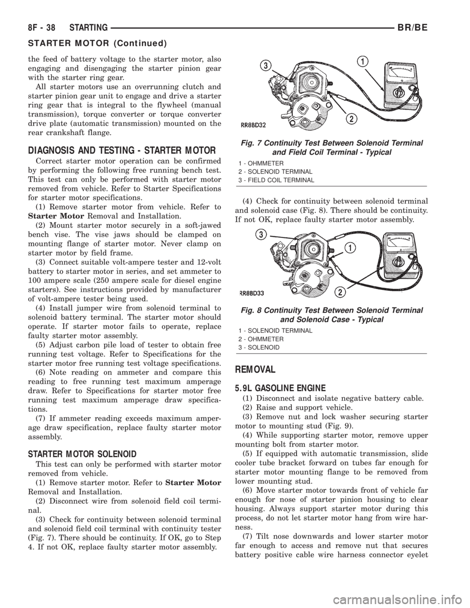
(3) Check for continuity between solenoid terminal
and solenoid field coil terminal with continuity tester
(Fig. 7). There should be continuity. If OK, go to Step
4. If not OK, replace faulty starter motor assembly.(4) Check for continuity between solenoid terminal
and solenoid case (Fig. 8). There should be continuity.
If not OK, replace faulty starter motor assembly.
REMOVAL
5.9L GASOLINE ENGINE
(1) Disconnect and isolate negative battery cable.
(2) Raise and support vehicle.
(3) Remove nut and lock washer securing starter
motor to mounting stud (Fig. 9).
(4) While supporting starter motor, remove upper
mounting bolt from starter motor.
(5) If equipped with automatic transmission, slide
cooler tube bracket forward on tubes far enough for
starter motor mounting flange to be removed from
lower mounting stud.
(6) Move starter motor towards front of vehicle far
enough for nose of starter pinion housing to clear
housing. Always support starter motor during this
process, do not let starter motor hang from wire har-
ness.
(7) Tilt nose downwards and lower starter motor
far enough to access and remove nut that secures
battery positive cable wire harness connector eyelet
Fig. 7 Continuity Test Between Solenoid Terminal
and Field Coil Terminal - Typical
1 - OHMMETER
2 - SOLENOID TERMINAL
3 - FIELD COIL TERMINAL
Fig. 8 Continuity Test Between Solenoid Terminal
and Solenoid Case - Typical
1 - SOLENOID TERMINAL
2 - OHMMETER
3 - SOLENOID
8F - 38 STARTINGBR/BE
STARTER MOTOR (Continued)