fuse box DODGE RAM 2003 Service User Guide
[x] Cancel search | Manufacturer: DODGE, Model Year: 2003, Model line: RAM, Model: DODGE RAM 2003Pages: 2895, PDF Size: 83.15 MB
Page 1130 of 2895
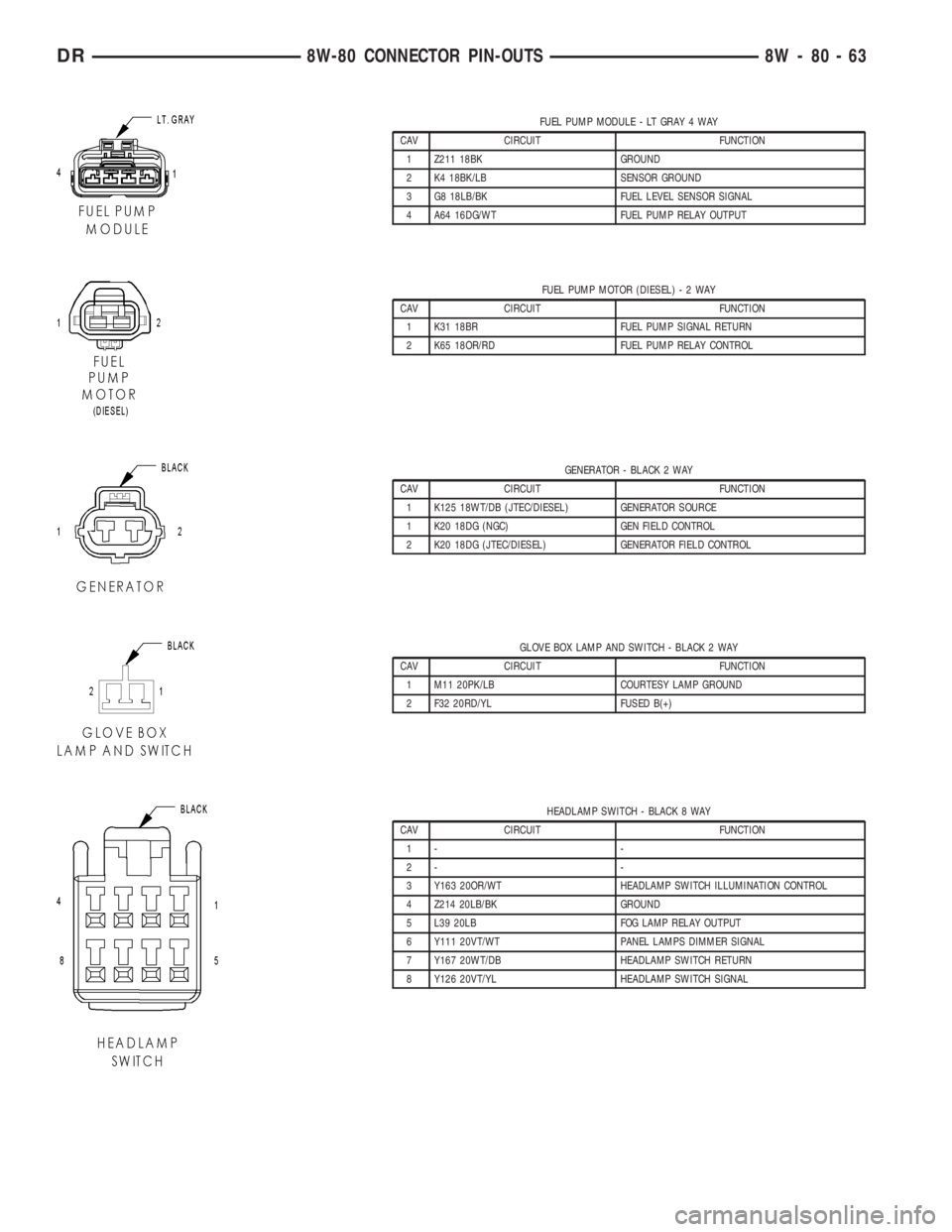
FUEL PUMP MODULE - LT GRAY 4 WAY
CAV CIRCUIT FUNCTION
1 Z211 18BK GROUND
2 K4 18BK/LB SENSOR GROUND
3 G8 18LB/BK FUEL LEVEL SENSOR SIGNAL
4 A64 16DG/WT FUEL PUMP RELAY OUTPUT
FUEL PUMP MOTOR (DIESEL)-2WAY
CAV CIRCUIT FUNCTION
1 K31 18BR FUEL PUMP SIGNAL RETURN
2 K65 18OR/RD FUEL PUMP RELAY CONTROL
GENERATOR - BLACK 2 WAY
CAV CIRCUIT FUNCTION
1 K125 18WT/DB (JTEC/DIESEL) GENERATOR SOURCE
1 K20 18DG (NGC) GEN FIELD CONTROL
2 K20 18DG (JTEC/DIESEL) GENERATOR FIELD CONTROL
GLOVE BOX LAMP AND SWITCH - BLACK 2 WAY
CAV CIRCUIT FUNCTION
1 M11 20PK/LB COURTESY LAMP GROUND
2 F32 20RD/YL FUSED B(+)
HEADLAMP SWITCH - BLACK 8 WAY
CAV CIRCUIT FUNCTION
1- -
2- -
3 Y163 20OR/WT HEADLAMP SWITCH ILLUMINATION CONTROL
4 Z214 20LB/BK GROUND
5 L39 20LB FOG LAMP RELAY OUTPUT
6 Y111 20VT/WT PANEL LAMPS DIMMER SIGNAL
7 Y167 20WT/DB HEADLAMP SWITCH RETURN
8 Y126 20VT/YL HEADLAMP SWITCH SIGNAL
DR8W-80 CONNECTOR PIN-OUTS 8W - 80 - 63
Page 1240 of 2895
8W-97 POWER DISTRIBUTION
TABLE OF CONTENTS
page page
POWER DISTRIBUTION
DESCRIPTION..........................1
OPERATION............................1
SPECIAL TOOLS
POWER DISTRIBUTION SYSTEMS.........2
CIGAR LIGHTER OUTLET
DESCRIPTION..........................2
OPERATION............................2
DIAGNOSIS AND TESTING - CIGAR LIGHTER
OUTLET.............................2
INTEGRATED POWER MODULE
DESCRIPTION..........................3
OPERATION............................3
REMOVAL.............................3
INSTALLATION..........................4
FRONT CONTROL MODULE
DESCRIPTION..........................4
OPERATION............................5
DIAGNOSIS AND TESTING - FRONT
CONTROL MODULE....................5
REMOVAL.............................5
INSTALLATION..........................5
IOD FUSE
DESCRIPTION..........................6OPERATION............................6
REMOVAL.............................6
INSTALLATION..........................7
POWER OUTLET
DESCRIPTION..........................7
OPERATION............................7
DIAGNOSIS AND TESTING - POWER OUTLET . 7
REMOVAL.............................7
INSTALLATION..........................7
RELAY
DESCRIPTION..........................8
OPERATION............................8
DIAGNOSIS AND TESTING - RELAY.........8
REMOVAL.............................9
INSTALLATION..........................9
MICRO RELAY
DESCRIPTION..........................9
OPERATION............................9
DIAGNOSIS AND TESTING - MICRO-RELAY . . . 9
REMOVAL.............................10
INSTALLATION.........................10
POWER DISTRIBUTION
DESCRIPTION
This group covers the various standard and
optional power distribution components used on this
model. The power distribution system for this vehicle
consists of the following components:
²Integrated Power Module (IPM)
²Front Control Module (FCM)
²Power Distribution Center (PDC)
²Power Outlets
²Cigar Lighter Outlets
²Relays
Refer to Wiring Diagrams for complete circuit sche-
matics.
The power distribution system also incorporates
various types of circuit control and protection fea-
tures, including:
²Automatic resetting circuit breakers
²Blade-type fuses
²Cartridge fuses
²RelaysFollowing are general descriptions of the major
components in the power distribution system. See the
owner's manual in the vehicle glove box for more
information on the features and use of all of the
power distribution system components.
OPERATION
The power distribution system for this vehicle is
designed to provide safe, reliable, and centralized dis-
tribution points for the electrical current required to
operate all of the many standard and optional facto-
ry-installed electrical and electronic powertrain,
chassis, safety, security, comfort and convenience sys-
tems. At the same time, the power distribution sys-
tem was designed to provide ready access to these
electrical distribution points for the vehicle techni-
cian to use when conducting diagnosis and repair of
faulty circuits. The power distribution system can
also prove useful for the sourcing of additional elec-
trical circuits that may be required to provide the
electrical current needed to operate many accessories
that the vehicle owner may choose to have installed
in the aftermarket.
DR8W-97 POWER DISTRIBUTION 8W - 97 - 1
Page 1245 of 2895
IOD FUSE
DESCRIPTION
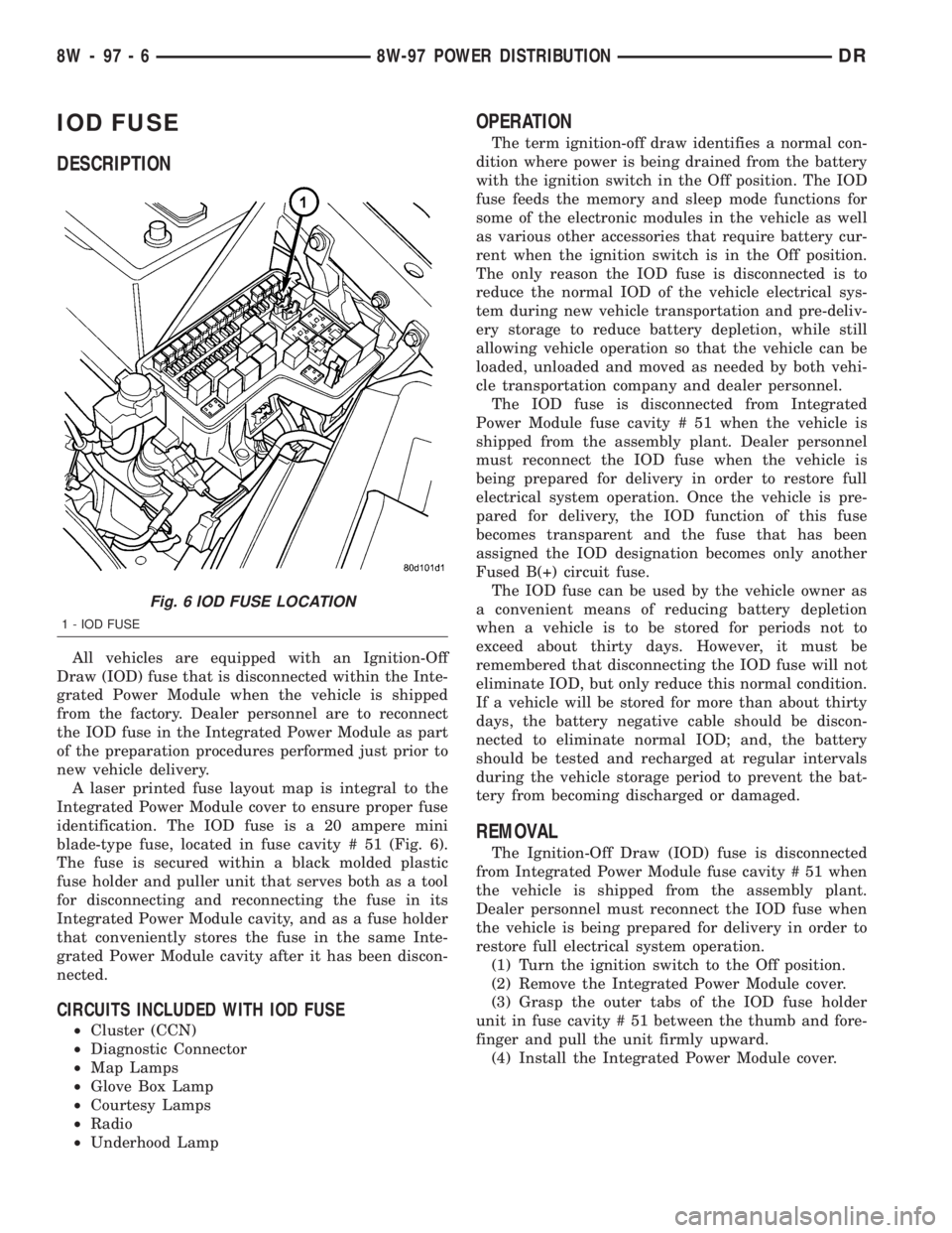
All vehicles are equipped with an Ignition-Off
Draw (IOD) fuse that is disconnected within the Inte-
grated Power Module when the vehicle is shipped
from the factory. Dealer personnel are to reconnect
the IOD fuse in the Integrated Power Module as part
of the preparation procedures performed just prior to
new vehicle delivery.
A laser printed fuse layout map is integral to the
Integrated Power Module cover to ensure proper fuse
identification. The IOD fuse is a 20 ampere mini
blade-type fuse, located in fuse cavity # 51 (Fig. 6).
The fuse is secured within a black molded plastic
fuse holder and puller unit that serves both as a tool
for disconnecting and reconnecting the fuse in its
Integrated Power Module cavity, and as a fuse holder
that conveniently stores the fuse in the same Inte-
grated Power Module cavity after it has been discon-
nected.
CIRCUITS INCLUDED WITH IOD FUSE
²Cluster (CCN)
²Diagnostic Connector
²Map Lamps
²Glove Box Lamp
²Courtesy Lamps
²Radio
²Underhood Lamp
OPERATION
The term ignition-off draw identifies a normal con-
dition where power is being drained from the battery
with the ignition switch in the Off position. The IOD
fuse feeds the memory and sleep mode functions for
some of the electronic modules in the vehicle as well
as various other accessories that require battery cur-
rent when the ignition switch is in the Off position.
The only reason the IOD fuse is disconnected is to
reduce the normal IOD of the vehicle electrical sys-
tem during new vehicle transportation and pre-deliv-
ery storage to reduce battery depletion, while still
allowing vehicle operation so that the vehicle can be
loaded, unloaded and moved as needed by both vehi-
cle transportation company and dealer personnel.
The IOD fuse is disconnected from Integrated
Power Module fuse cavity # 51 when the vehicle is
shipped from the assembly plant. Dealer personnel
must reconnect the IOD fuse when the vehicle is
being prepared for delivery in order to restore full
electrical system operation. Once the vehicle is pre-
pared for delivery, the IOD function of this fuse
becomes transparent and the fuse that has been
assigned the IOD designation becomes only another
Fused B(+) circuit fuse.
The IOD fuse can be used by the vehicle owner as
a convenient means of reducing battery depletion
when a vehicle is to be stored for periods not to
exceed about thirty days. However, it must be
remembered that disconnecting the IOD fuse will not
eliminate IOD, but only reduce this normal condition.
If a vehicle will be stored for more than about thirty
days, the battery negative cable should be discon-
nected to eliminate normal IOD; and, the battery
should be tested and recharged at regular intervals
during the vehicle storage period to prevent the bat-
tery from becoming discharged or damaged.
REMOVAL
The Ignition-Off Draw (IOD) fuse is disconnected
from Integrated Power Module fuse cavity # 51 when
the vehicle is shipped from the assembly plant.
Dealer personnel must reconnect the IOD fuse when
the vehicle is being prepared for delivery in order to
restore full electrical system operation.
(1) Turn the ignition switch to the Off position.
(2) Remove the Integrated Power Module cover.
(3) Grasp the outer tabs of the IOD fuse holder
unit in fuse cavity # 51 between the thumb and fore-
finger and pull the unit firmly upward.
(4) Install the Integrated Power Module cover.
Fig. 6 IOD FUSE LOCATION
1 - IOD FUSE
8W - 97 - 6 8W-97 POWER DISTRIBUTIONDR
Page 2789 of 2895
for relay terminal 86 with the ignition switch in the
On position. If OK, go to Step 5. If not OK, repair the
open circuit to the fuse in the junction block as
required.
(5) The coil ground terminal cavity (85) is switched
to ground through the Powertrain Control Module
(PCM). There should be continuity between this cav-
ity and the A/C compressor clutch relay control cir-
cuit cavity of the PCM wire harness connector C
(gray) at all times. If not OK, repair the open circuit
as required.
REMOVAL
(1) Disconnect and isolate the battery negative
cable.
(2) Remove the cover from the Power Distribution
Center (PDC).
(3) Refer to the label on the PDC for compressor
clutch relay identification and location.
(4) Unplug the compressor clutch relay from the
PDC.
INSTALLATION
(1) Install the compressor clutch relay by aligning
the relay terminals with the cavities in the PDC and
pushing the relay firmly into place.
(2) Install the PDC cover.
(3) Connect the battery negative cable.
(4) Test the relay operation.
A/C HEATER CONTROL
DESCRIPTION
The A/C heater system uses a seriers of electrical
controls. These controls provide the vehicle operator
with a number of setting options to help control the
climate and comfort within the vehicle. Refer to the
owner's manual in the vehicle glove box for more
information on the features, use, and suggested oper-
ation of these controls.
The A/C heater control - (Single Zone) or (Dual
Zone) panel is located to the right of the instrument
cluster on the instrument panel.
The control panel contains a rotary-type tempera-
ture control, a rotary-type mode control switch knob,
and a rotary-type blower motor speed switch knob.
The control also has a push button to activate the
Optional side view mirrors defroster elements and to
turn the A/C on.
The Dual Zone HVAC control panel contains a pair
of slider-type temperature controls, a rotary-type
mode control switch knob and a rotary-type blower
motor speed switch knob. The control also has but-
tons to turn the A/C ON, Set it on Max A/C and for
the Optional Heated Sideview Mirrors.The A/C heater control panel cannot be repaired. If
faulty or damaged, the entire unit must be replaced.
The illumination lamps are available for service
replacement.
REMOVAL
WARNING: ON VEHICLES EQUIPPED WITH AIR-
BAGS, DISABLE THE AIRBAG SYSTEM BEFORE
ATTEMPTING ANY STEERING WHEEL, STEERING
COLUMN, OR INSTRUMENT PANEL COMPONENT
DIAGNOSIS OR SERVICE. DISCONNECT AND ISO-
LATE THE BATTERY NEGATIVE (GROUND) CABLE,
THEN WAIT TWO MINUTES FOR THE AIRBAG SYS-
TEM CAPACITOR TO DISCHARGE BEFORE PER-
FORMING FURTHER DIAGNOSIS OR SERVICE. THIS
IS THE ONLY SURE WAY TO DISABLE THE AIRBAG
SYSTEM. FAILURE TO TAKE THE PROPER PRE-
CAUTIONS COULD RESULT IN AN ACCIDENTAL
AIRBAG DEPLOYMENT AND POSSIBLE PERSONAL
INJURY.
(1) Disconnect and isolate the battery negative
cable.
(2) Remove the center bezel from the instrument
panel(Refer to 23 - BODY/INSTRUMENT PANEL/IN-
STRUMENT PANEL CENTER BEZEL - REMOVAL).
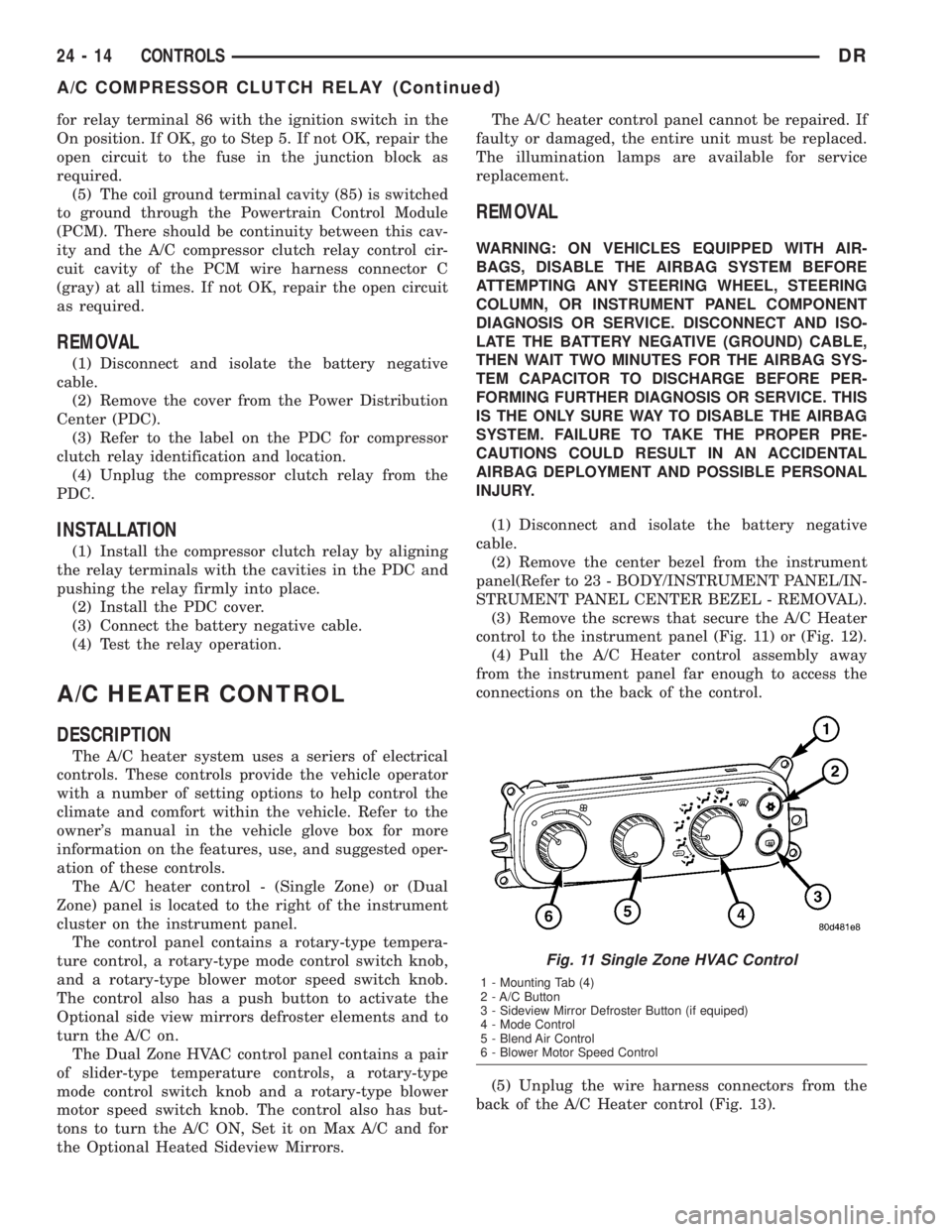
(3) Remove the screws that secure the A/C Heater
control to the instrument panel (Fig. 11) or (Fig. 12).
(4) Pull the A/C Heater control assembly away
from the instrument panel far enough to access the
connections on the back of the control.
(5) Unplug the wire harness connectors from the
back of the A/C Heater control (Fig. 13).
Fig. 11 Single Zone HVAC Control
1 - Mounting Tab (4)
2 - A/C Button
3 - Sideview Mirror Defroster Button (if equiped)
4 - Mode Control
5 - Blend Air Control
6 - Blower Motor Speed Control
24 - 14 CONTROLSDR
A/C COMPRESSOR CLUTCH RELAY (Continued)
Page 2800 of 2895
(1) Recover refrigerant(Refer to 24 - HEATING &
AIR CONDITIONING/PLUMBING - STANDARD
PROCEDURE).
(2) Remove and disassemble the HVAC housing.
(Refer to 24 - HEATING & AIR CONDITIONING/
DISTRIBUTION/HVAC HOUSING - REMOVAL)
(Refer to 24 - HEATING & AIR CONDITIONING/
DISTRIBUTION/HVAC HOUSING - DISASSEMBLY)
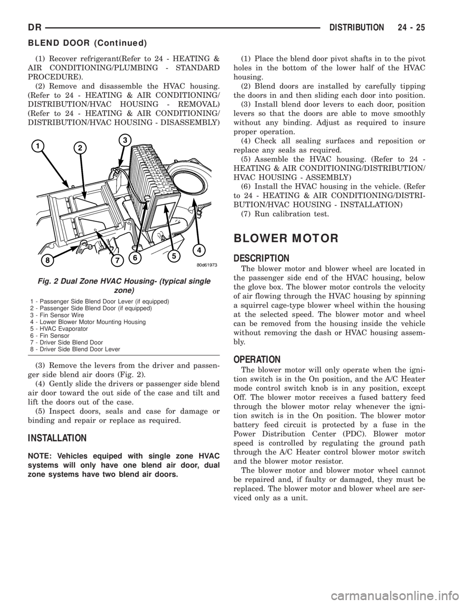
(3) Remove the levers from the driver and passen-
ger side blend air doors (Fig. 2).
(4) Gently slide the drivers or passenger side blend
air door toward the out side of the case and tilt and
lift the doors out of the case.
(5) Inspect doors, seals and case for damage or
binding and repair or replace as required.
INSTALLATION
NOTE: Vehicles equiped with single zone HVAC
systems will only have one blend air door, dual
zone systems have two blend air doors.(1) Place the blend door pivot shafts in to the pivot
holes in the bottom of the lower half of the HVAC
housing.
(2) Blend doors are installed by carefully tipping
the doors in and then sliding each door into position.
(3) Install blend door levers to each door, position
levers so that the doors are able to move smoothly
without any binding. Adjust as required to insure
proper operation.
(4) Check all sealing surfaces and reposition or
replace any seals as required.
(5) Assemble the HVAC housing. (Refer to 24 -
HEATING & AIR CONDITIONING/DISTRIBUTION/
HVAC HOUSING - ASSEMBLY)
(6) Install the HVAC housing in the vehicle. (Refer
to 24 - HEATING & AIR CONDITIONING/DISTRI-
BUTION/HVAC HOUSING - INSTALLATION)
(7) Run calibration test.
BLOWER MOTOR
DESCRIPTION
The blower motor and blower wheel are located in
the passenger side end of the HVAC housing, below
the glove box. The blower motor controls the velocity
of air flowing through the HVAC housing by spinning
a squirrel cage-type blower wheel within the housing
at the selected speed. The blower motor and wheel
can be removed from the housing inside the vehicle
without removing the dash or HVAC housing assem-
bly.
OPERATION
The blower motor will only operate when the igni-
tion switch is in the On position, and the A/C Heater
mode control switch knob is in any position, except
Off. The blower motor receives a fused battery feed
through the blower motor relay whenever the igni-
tion switch is in the On position. The blower motor
battery feed circuit is protected by a fuse in the
Power Distribution Center (PDC). Blower motor
speed is controlled by regulating the ground path
through the A/C Heater control blower motor switch
and the blower motor resistor.
The blower motor and blower motor wheel cannot
be repaired and, if faulty or damaged, they must be
replaced. The blower motor and blower wheel are ser-
viced only as a unit.
Fig. 2 Dual Zone HVAC Housing- (typical single
zone)
1 - Passenger Side Blend Door Lever (if equipped)
2 - Passenger Side Blend Door (if equipped)
3 - Fin Sensor Wire
4 - Lower Blower Motor Mounting Housing
5 - HVAC Evaporator
6 - Fin Sensor
7 - Driver Side Blend Door
8 - Driver Side Blend Door Lever
DRDISTRIBUTION 24 - 25
BLEND DOOR (Continued)
Page 2870 of 2895

FUEL INJECTOR RAIL - DESCRIPTION....14-89
FUEL INJECTOR RAIL - INSTALLATION....14-90
FUEL INJECTOR RAIL - OPERATION......14-89
FUEL INJECTOR RAIL - REMOVAL.......14-89
FUEL LEVEL SENDING UNIT / SENSOR -
DESCRIPTION...................14-68,14-7
FUEL LEVEL SENDING UNIT / SENSOR -
INSTALLATION........................14-8
FUEL LEVEL SENDING UNIT / SENSOR -
OPERATION.....................14-68,14-7
FUEL LEVEL SENDING UNIT / SENSOR -
REMOVAL...........................14-7
FUEL LINE LEAKS - DIAGNOSIS AND
TESTING, HIGH-PRESSURE.............14-69
FUEL LINES - DESCRIPTION........14-69,14-8
FUEL LINES - INSTALLATION...........14-71
FUEL LINES - OPERATION..............14-69
FUEL LINES - REMOVAL...............14-69
FUEL PRESSURE LIMITING VALVE -
DESCRIPTION.......................14-72
FUEL PRESSURE LIMITING VALVE -
INSTALLATION.......................14-73
FUEL PRESSURE LIMITING VALVE -
OPERATION.........................14-72
FUEL PRESSURE LIMITING VALVE -
REMOVAL..........................14-72
FUEL PRESSURE SENSOR -
DESCRIPTION.......................14-72
FUEL PRESSURE SENSOR -
INSTALLATION.......................14-72
FUEL PRESSURE SENSOR - OPERATION....14-72
FUEL PRESSURE SENSOR - REMOVAL....14-72
FUEL PUMP - DESCRIPTION............14-12
FUEL PUMP - OPERATION.............14-12
FUEL PUMP MODULE - DESCRIPTION....14-12
FUEL PUMP MODULE - INSTALLATION . . . 14-13
FUEL PUMP MODULE - OPERATION......14-12
FUEL PUMP MODULE - REMOVAL.......14-12
FUEL PUMP RELAY - DESCRIPTION......14-33
FUEL PUMP RELAY - INSTALLATION.....14-33
FUEL PUMP RELAY - OPERATION........14-33
FUEL PUMP RELAY - REMOVAL.........14-33
FUEL PUMP RELAYS - DIAGNOSIS AND
TESTING, ASD........................8I-7
FUEL RAIL - DESCRIPTION.............14-13
FUEL RAIL - INSTALLATION............14-18
FUEL RAIL - OPERATION...............14-13
FUEL RAIL - REMOVAL................14-13
FUEL REQUIREMENTS - DIESEL ENGINE
- DESCRIPTION........................0-1
FUEL SENSOR - DESCRIPTION, WATER
IN ................................14-77
FUEL SENSOR - OPERATION, WATER IN . . 14-78
FUEL SENSOR - REMOVAL, WATER IN....14-78
FUEL SYSTEM - DESCRIPTION, DIESEL . . . 14-57
FUEL SYSTEM - TORQUE...............14-3
FUEL SYSTEM PARTS - STANDARD
PROCEDURES, CLEANING..............14-58
FUEL SYSTEM PRESSURE, DIESEL.......14-60
FUEL SYSTEM PRESSURE RELEASE -
STANDARD PROCEDURE................14-2
FUEL SYSTEM PRESSURE,
SPECIFICATIONS......................14-3
FUEL SYSTEM PRIMING - STANDARD
PROCEDURE........................14-59
FUEL SYSTEM, SPECIAL TOOLS..........14-5
FUEL SYSTEM, SPECIAL TOOLS -
DIESEL............................14-60
FUEL TANK - DESCRIPTION............14-20
FUEL TANK - OPERATION..............14-20
FUEL TANK MODULE - DESCRIPTION.....14-75
FUEL TANK MODULE - INSTALLATION....14-75
FUEL TANK MODULE - OPERATION......14-75
FUEL TANK MODULE - REMOVAL........14-75
FUEL TRANSFER PUMP - DESCRIPTION . . 14-75
FUEL TRANSFER PUMP - INSTALLATION . . 14-76
FUEL TRANSFER PUMP - OPERATION....14-76
FUEL TRANSFER PUMP - REMOVAL......14-76
FULL SIZE, SPARE WHEEL WITH
MATCHING TIRE - DESCRIPTION........22-15
FUNCTIONS - DESCRIPTION, CIRCUIT . . 8W-01-6
FUSE - DESCRIPTION, IOD
...........8W-97-6
FUSE - INSTALLATION, IOD
..........8W-97-7
FUSE - OPERATION, IOD
.............8W-97-6
FUSE - REMOVAL, IOD
..............8W-97-6
FUSES POWERING SEVERAL LOADS -
STANDARD PROCEDURE, TESTING
FOR A SHORT TO GROUND ON
......8W-01-10GAP AND FLUSH - SPECIFICATIONS......23-95
GAS - DESCRIPTION, FUEL DELIVERY.....14-1
GAS - INSTALLATION............19-30,19-41
GAS - OPERATION, FUEL DELIVERY.......14-2
GAS - REMOVAL................19-29,19-40
GAS ENGINE - DIAGNOSIS AND TESTING . . 11-2
GAS ENGINE - INSTALLATION...........19-24
GAS ENGINE - REMOVAL..............19-23
GASKET - DESCRIPTION, CYLINDER
HEAD COVER........................9-243
GASKET - DIAGNOSIS AND TESTING,
CYLINDER HEAD......................9-20
GASKET - OPERATION, CYLINDER HEAD
COVER.............................9-243
GASKET FAILURE - DIAGNOSIS AND
TESTING, CYLINDER HEAD . . . 9-194,9-243,9-370
GASKET SELECTION - STANDARD
PROCEDURE, HEAD...................9-330
GASKET SURFACE PREPARATION -
STANDARD PROCEDURE, ENGINE........9-10
GASKETS AND SEALERS - STANDARD
PROCEDURE, FORM-IN-PLACE....9-232,9-289,
9-360,9-9,9-93
GAUGE - DESCRIPTION, ENGINE
TEMPERATURE......................8J-23
GAUGE - DESCRIPTION, FUEL...........8J-25
GAUGE - DESCRIPTION, OIL PRESSURE . . 8J-32
GAUGE - DESCRIPTION, VOLTAGE.......8J-40
GAUGE - OPERATION, ENGINE
TEMPERATURE......................8J-23
GAUGE - OPERATION, FUEL............8J-26
GAUGE - OPERATION, OIL PRESSURE....8J-32
GAUGE - OPERATION, VOLTAGE.........8J-41
GAUGES - DIAGNOSIS AND TESTING,
PRESSURE..........................22-7
GAUGES INDICATOR - DESCRIPTION,
CHECK.............................8J-21
GAUGES INDICATOR - OPERATION,
CHECK.............................8J-21
GEAR - DESCRIPTION, CRANKSHAFT.....9-322
GEAR - INDEPENDENT FRONT
SUSPENSION - DESCRIPTION...........19-16
GEAR - INDEPENDENT FRONT
SUSPENSION - INSTALLATION..........19-17
GEAR - INDEPENDENT FRONT
SUSPENSION - REMOVAL..............19-16
GEAR - INSTALLATION................9-322
GEAR - INSTALLATION, PINION
GEAR/RING......................3-42,3-66
GEAR - LINK/COIL - DESCRIPTION.......19-19
GEAR - LINK/COIL - INSTALLATION......19-20
GEAR - LINK/COIL - OPERATION........19-19
GEAR - LINK/COIL - REMOVAL..........19-19
GEAR - REMOVAL....................9-322
GEAR - REMOVAL, PINION GEAR/RING....3-40,
3-65
GEAR HOUSING - INSTALLATION........9-349
GEAR HOUSING - REMOVAL............9-348
GEAR HOUSING COVER - INSTALLATION . . 9-350
GEAR HOUSING COVER - REMOVAL.....9-349
GEAR INPUT SHAFT SEAL -
INSTALLATION, STEERING.............19-28
GEAR INPUT SHAFT SEAL - REMOVAL,
STEERING..........................19-25
GEAR SELECTOR INDICATOR -
DESCRIPTION.......................8J-26
GEAR SELECTOR INDICATOR -
OPERATION.........................8J-27
GEAR SHIFT LEVER - INSTALLATION.....19-12
GEAR SHIFT LEVER - REMOVAL.........19-12
GEAR, SPECIAL TOOLS - POWER
STEERING..........................19-22
GEAR, SPECIFICATIONS - POWER
STEERING..........................19-21
GEAR TO COOLER - INSTALLATION,
RETURN HOSE.................19-43,19-44
GEAR TO COOLER - REMOVAL, RETURN
HOSE..............................19-43
GEAR/RING GEAR - INSTALLATION,
PINION
.........................3-42,3-66
GEAR/RING GEAR - REMOVAL, PINION
....3-40,
3-65
GEAR/RING GEAR/TONE RING -
INSTALLATION, PINION
.......3-123,3-150,3-96
GEAR/RING GEAR/TONE RING -
REMOVAL, PINION
..........3-122,3-149,3-94
GEARSHIFT CABLE - DIAGNOSIS AND
TESTING
..............21-209,21-389,21-544GEARSHIFT CABLE - INSTALLATION....21-210,
21-390,21-545
GEARSHIFT CABLE - REMOVAL . . 21-209,21-389,
21-544
GEARSHIFT CABLE, ADJUSTMENTS.....21-211,
21-391,21-546
GEAR/TONE RING - INSTALLATION,
PINION GEAR/RING..........3-123,3-150,3-96
GEAR/TONE RING - REMOVAL, PINION
GEAR/RING................3-122,3-149,3-94
GEARTRAIN - ASSEMBLY, PLANETARY . . . 21-573
GEARTRAIN - CLEANING, PLANETARY . . . 21-573
GEARTRAIN - DESCRIPTION,
PLANETARY........................21-571
GEARTRAIN - DISASSEMBLY,
PLANETARY........................21-573
GEARTRAIN - INSPECTION, PLANETARY . 21-573
GEARTRAIN - OPERATION, PLANETARY . . 21-571
GEARTRAIN/OUTPUT SHAFT -
ASSEMBLY, PLANETARY........21-245,21-423
GEARTRAIN/OUTPUT SHAFT -
DESCRIPTION, PLANETARY......21-242,21-420
GEARTRAIN/OUTPUT SHAFT -
DISASSEMBLY, PLANETARY.....21-243,21-421
GEARTRAIN/OUTPUT SHAFT -
INSPECTION, PLANETARY.......21-245,21-422
GEARTRAIN/OUTPUT SHAFT -
OPERATION, PLANETARY.......21-243,21-420
GENERAL - WARNINGS.............8W-01-7
GENERATOR / CHARGING SYSTEM -
SPECIFICATIONS, TORQUE.............8F-20
GENERATOR - DESCRIPTION.............8F-22
GENERATOR - INSTALLATION...........8F-25
GENERATOR - OPERATION.............8F-22
GENERATOR - REMOVAL...............8F-22
GENERATOR RATINGS, SPECIFICATIONS . . 8F-20
GENII - ASSEMBLY, TRANSFER CASE -
NV241............................21-604
GENII - CLEANING, TRANSFER CASE -
NV241............................21-602
GENII - DESCRIPTION, TRANSFER CASE
- NV241..............................0-4
GENII - DESCRIPTION, TRANSFER CASE
- NV241...........................21-591
GENII - DIAGNOSIS AND TESTING,
TRANSFER CASE - NV241.............21-592
GENII - DISASSEMBLY, TRANSFER CASE
- NV241...........................21-593
GENII - INSPECTION, TRANSFER CASE -
NV241............................21-602
GENII - INSTALLATION, TRANSFER CASE
- NV241...........................21-614
GENII - OPERATION, TRANSFER CASE -
NV241............................21-591
GENII - REMOVAL, TRANSFER CASE -
NV241............................21-593
GENII - TRANSFER CASE, NV241.......21-614
GLASS - INSTALLATION, BACKLITE VENT . 23-87
GLASS - INSTALLATION, DOOR....23-20,23-30
GLASS - INSTALLATION, SIDE VIEW
MIRROR...........................23-44
GLASS - REMOVAL, BACKLITE VENT.....23-87
GLASS - REMOVAL, DOOR........23-20,23-30
GLASS - REMOVAL, SIDE VIEW MIRROR . . 23-42
GLASS RUN CHANNEL - INSTALLATION . . 23-21,
23-31
GLASS RUN CHANNEL - REMOVAL . 23-21,23-30
GLASS RUN WEATHERSTRIP -
INSTALLATION, FRONT DOOR...........23-92
GLASS RUN WEATHERSTRIP -
INSTALLATION, REAR DOOR............23-93
GLASS RUN WEATHERSTRIP -
REMOVAL, FRONT DOOR..............23-92
GLASS RUN WEATHERSTRIP -
REMOVAL, REAR DOOR...............23-93
GLOVE BOX - INSTALLATION...........23-53
GLOVE BOX - REMOVAL...............23-53
GLOVE BOX LAMP/SWITCH -
INSTALLATION.......................8L-25
GLOVE BOX LAMP/SWITCH - REMOVAL . . . 8L-25
GLOVE BOX LATCH - INSTALLATION
.....23-53
GLOVE BOX LATCH - REMOVAL
.........23-53
GOVERNOR - DESCRIPTION,
ELECTRONIC
.................21-196,21-376
GOVERNOR - INSTALLATION,
ELECTRONIC
.................21-199,21-379
GOVERNOR - OPERATION, ELECTRONIC
. 21-196,
21-377
DRINDEX 15
Description Group-Page Description Group-Page Description Group-Page