power steering fluid DODGE RAM 2003 Service User Guide
[x] Cancel search | Manufacturer: DODGE, Model Year: 2003, Model line: RAM, Model: DODGE RAM 2003Pages: 2895, PDF Size: 83.15 MB
Page 254 of 2895
CONDITION POSSIBLE CAUSES CORRECTION
Brakes Self Apply 1. Dump valve faulty. 1. Replace booster.
2. Contamination in hydraulic
system.2. Flush hydraulic system and replace
booster.
3. Restriction in booster return hose. 3. Replace hose.
Booster Chatter, Pedal
Vibration1. Slipping pump belt. 1. Replace power steering belt.
2. Low pump fluid level. 2. Fill pump and check for leaks.
Grabbing Brakes 1. Low pump flow. 1. Test and repair/replace pump.
2. Faulty spool valve action. 2. Replace booster.
STANDARD PROCEDURE - BLEEDING
The hydraulic booster is generally self-bleeding,
this procedure will normally bleed the air from the
booster. Normal driving and operation of the unit will
remove any remaining trapped air.
(1) Fill power steering pump reservoir.
(2) Disconnect fuel shutdown relay and crank the
engine for several seconds, Refer to Fuel System for
relay location and WARNING.
(3) Check fluid level and add if necessary.
(4) Connect fuel shutdown relay and start the
engine.
(5) Turn the steering wheel slowly from lock to
lock twice.
(6) Stop the engine and discharge the accumulator
by depressing the brake pedal 5 times.
(7) Start the engine and turn the steering wheel
slowly from lock to lock twice.
(8) Turn off the engine and check fluid level and
add if necessary.
NOTE: If fluid foaming occurs, wait for foam to dis-
sipate and repeat steps 7 and 8.
REMOVAL
NOTE: If the booster is being replaced because the
power steering fluid is contaminated, flush the
power steering system before replacing the booster.
(1) With engine off depress the brake pedal 5
times to discharge the accumulator.
(2) Remove brake lines from master cylinder.
(3) Remove mounting nuts from the master cylin-
der.
(4) Remove the bracket from the hydraulic booster
lines and master cylinder mounting studs.
(5) Remove the master cylinder.
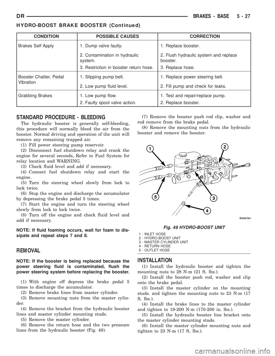
(6) Remove the return hose and the two pressure
lines from the hydraulic booster (Fig. 49).(7) Remove the booster push rod clip, washer and
rod remove from the brake pedal.
(8) Remove the mounting nuts from the hydraulic
booster and remove the booster.INSTALLATION
(1) Install the hydraulic booster and tighten the
mounting nuts to 28 N´m (21 ft. lbs.).
(2) Install the booster push rod, washer and clip
onto the brake pedal.
(3) Install the master cylinder on the mounting
studs. and tighten the mounting nuts to 23 N´m (17
ft. lbs.).
(4) Install the brake lines to the master cylinder
and tighten to 19-200 N´m (170-200 in. lbs.).
(5) Install the hydraulic booster line bracket onto
the master cylinder mounting studs.
(6) Install the master cylinder mounting nuts and
tighten to 23 N´m (17 ft. lbs.).
Fig. 49 HYDRO-BOOST UNIT
1 - INLET HOSE
2 - HYDRO-BOOST UNIT
3 - MASTER CYLINDER UNIT
4 - RETURN HOSE
5 - OUTLET HOSE
DRBRAKES - BASE 5 - 27
HYDRO-BOOST BRAKE BOOSTER (Continued)
Page 255 of 2895

(7) Install the hydraulic booster pressure lines to
the bracket and booster.
(8) Tighten the pressure lines to 41 N´m (30 ft.
lbs.).
NOTE: Inspect o-rings on the pressure line fittings
to insure they are in good condition before installa-
tion. Replace o-rings if necessary.
(9) Install the return hose to the booster.
(10) Bleed base brake system, (Refer to 5 -
BRAKES/HYDRAULIC/MECHANICAL - STAN-
DARD PROCEDURE).
(11) Fill the power steering pump with fluid,
(Refer to 19 - STEERING/PUMP - STANDARD PRO-
CEDURE).
CAUTION: MOPAR (MS-9602) ATF+4 is to be used in
the power steering system. No other power steering
or automatic transmission fluid is to be used in the
system. Damage may result to the power steering
pump and system if any other fluid is used, and do
not overfill.
(12) Bleed the hydraulic booster (Refer to 5 -
BRAKES/HYDRAULIC/MECHANICAL/POWER
BRAKE BOOSTER - STANDARD PROCEDURE).
ROTORS
REMOVAL
REMOVAL - REAR
(1) Raise and support the vehicle
(2) Remove the tire and wheel assembly.
(3) Remove the disc brake caliper, (Refer to 5 -
BRAKES/HYDRAULIC/MECHANICAL/DISC
BRAKE CALIPERS - REMOVAL).
(4) Remove the caliper adapter bolts (Fig.
50).(Refer to 5 - BRAKES/HYDRAULIC/MECHANI-
CAL/DISC BRAKE CALIPER ADAPTER -
REMOVAL)
(5) Remove the retianing clips and rotor assembly
(Fig. 50).
REMOVAL - FRONT
(1) Raise and support the vehicle.
(2) Remove the wheel and tire assembly.
(3) Remove the caliper from the steering knuckle,
(Refer to 5 - BRAKES/HYDRAULIC/MECHANICAL/
DISC BRAKE CALIPERS - REMOVAL) and remove
caliper adapter assembly (Fig. 51).
NOTE: Do not allow brake hose to support caliper
adapter assembly.(4) Remove the rotor from the hub/bearing wheel
studs (Fig. 52) or (Fig. 53).
INSTALLATION
INSTALLATION - REAR
(1) Install the rotor to the axleshaft (Fig. 50).
Fig. 50 REAR ROTOR
1 - ROTOR
2 - CALIPER ADAPTER
3 - CALIPER
Fig. 51 Caliper Adapter Assembly
1 - KNUCKLE
2 - CALIPER
3 - ROTOR
5 - 28 BRAKES - BASEDR
HYDRO-BOOST BRAKE BOOSTER (Continued)
Page 266 of 2895
BRAKES - ABS
TABLE OF CONTENTS
page page
BRAKES - ABS
DESCRIPTION.........................39
OPERATION...........................39
STANDARD PROCEDURE - ABS BRAKE
BLEEDING...........................40
SPECIFICATIONS
TORQUE CHART......................40
FRONT WHEEL SPEED SENSOR
DESCRIPTION.........................41
OPERATION...........................41
REMOVAL.............................41
INSTALLATION.........................42
REAR WHEEL SPEED SENSOR
DIAGNOSIS AND TESTING - REAR WHEEL
ANTILOCK...........................42
REMOVAL.............................42
INSTALLATION.........................43
TONE WHEEL
DIAGNOSIS AND TESTING - REAR WHEEL
SPEED SENSOR......................43HYDRAULIC/MECHANICAL
DESCRIPTION - ELECTRONIC VARIABLE
BRAKE PROPORTIONING...............43
OPERATION - ELECTRONIC VARIABLE
BRAKE PROPORTIONING...............43
HCU (HYDRAULIC CONTROL UNIT)
DESCRIPTION.........................43
OPERATION...........................43
REMOVAL.............................44
INSTALLATION.........................44
R WA L VA LV E
DESCRIPTION.........................44
OPERATION...........................44
REMOVAL.............................45
INSTALLATION.........................45
BRAKES - ABS
DESCRIPTION
The antilock brake system (ABS) is an electroni-
cally operated, three channel brake control system.
The vehicle has Electronic Variable Brake Propor-
tioning (EVBP) designed into the system which elim-
inates the combination/proportioning valve.
The system is designed to prevent wheel lockup
and maintain steering control during braking. Pre-
venting lockup is accomplished by modulating fluid
pressure to the wheel brake units.
The hydraulic system is a three channel design.
The front wheel brakes are controlled individually
and the rear wheel brakes in tandem. The ABS elec-
trical system is separate from other electrical circuits
in the vehicle. A specially programmed controller
antilock brake unit operates the system components.
ABS system major components include:
²Controller Antilock Brakes (CAB)
²Hydraulic Control Unit (HCU)
²Wheel Speed Sensors (WSS)
²ABS Warning Light
OPERATION
Battery voltage is supplied to the CAB. The CAB
performs a system initialization procedure at start
up. A check of the ABS motor is performed at 15
miles per hour. Initialization consists of a static and
dynamic self check of system electrical components.
The static and dynamic checks occurs at ignition
start up. During the dynamic check, the CAB briefly
cycles solenoids to verify operation. An audible noise
may be heard during this self check. This noise
should be considered normal. The ABS motor and
pump are then checked at a speed of 15 mile per
hour.
If an ABS component exhibits a fault during ini-
tialization, the CAB illuminates the amber warning
light and registers a fault code in the microprocessor
memory.
The CAB monitors wheel speed sensor inputs con-
tinuously while the vehicle is in motion. However,
the CAB will not activate any ABS components as
long as sensor inputs indicate normal braking.
During normal braking, the master cylinder, power
booster and wheel brake units all function as they
would in a vehicle without ABS. The HCU compo-
nents are not activated.
DRBRAKES - ABS 5 - 39
Page 347 of 2895
(6) Remove the power steering cooler mounting
bolts and position the power steering cooler out of
the way.
(7) Disconnect the transmission cooler lines at the
transmission. The transmission cooler will remain on
the radiator and can be removed as an assembly.
(8) Remove the lower shroud assembly and the
electronic viscous fan wiring from the upper shroud
assembly.
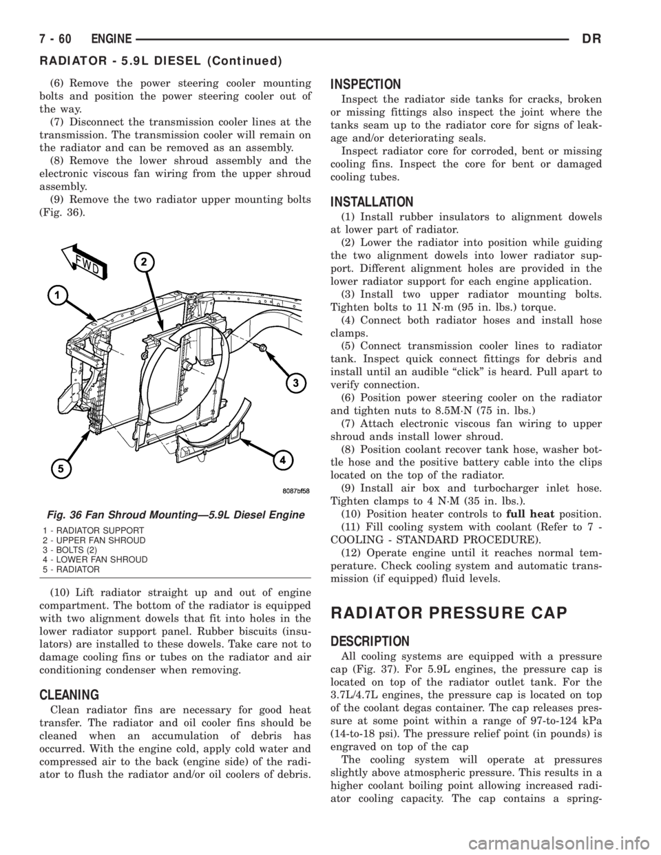
(9) Remove the two radiator upper mounting bolts
(Fig. 36).
(10) Lift radiator straight up and out of engine
compartment. The bottom of the radiator is equipped
with two alignment dowels that fit into holes in the
lower radiator support panel. Rubber biscuits (insu-
lators) are installed to these dowels. Take care not to
damage cooling fins or tubes on the radiator and air
conditioning condenser when removing.
CLEANING
Clean radiator fins are necessary for good heat
transfer. The radiator and oil cooler fins should be
cleaned when an accumulation of debris has
occurred. With the engine cold, apply cold water and
compressed air to the back (engine side) of the radi-
ator to flush the radiator and/or oil coolers of debris.
INSPECTION
Inspect the radiator side tanks for cracks, broken
or missing fittings also inspect the joint where the
tanks seam up to the radiator core for signs of leak-
age and/or deteriorating seals.
Inspect radiator core for corroded, bent or missing
cooling fins. Inspect the core for bent or damaged
cooling tubes.
INSTALLATION
(1) Install rubber insulators to alignment dowels
at lower part of radiator.
(2) Lower the radiator into position while guiding
the two alignment dowels into lower radiator sup-
port. Different alignment holes are provided in the
lower radiator support for each engine application.
(3) Install two upper radiator mounting bolts.
Tighten bolts to 11 N´m (95 in. lbs.) torque.
(4) Connect both radiator hoses and install hose
clamps.
(5) Connect transmission cooler lines to radiator
tank. Inspect quick connect fittings for debris and
install until an audible ªclickº is heard. Pull apart to
verify connection.
(6) Position power steering cooler on the radiator
and tighten nuts to 8.5M´N (75 in. lbs.)
(7) Attach electronic viscous fan wiring to upper
shroud ands install lower shroud.
(8) Position coolant recover tank hose, washer bot-
tle hose and the positive battery cable into the clips
located on the top of the radiator.
(9) Install air box and turbocharger inlet hose.
Tighten clamps to 4 N´M (35 in. lbs.).
(10) Position heater controls tofull heatposition.
(11) Fill cooling system with coolant (Refer to 7 -
COOLING - STANDARD PROCEDURE).
(12) Operate engine until it reaches normal tem-
perature. Check cooling system and automatic trans-
mission (if equipped) fluid levels.
RADIATOR PRESSURE CAP
DESCRIPTION
All cooling systems are equipped with a pressure
cap (Fig. 37). For 5.9L engines, the pressure cap is
located on top of the radiator outlet tank. For the
3.7L/4.7L engines, the pressure cap is located on top
of the coolant degas container. The cap releases pres-
sure at some point within a range of 97-to-124 kPa
(14-to-18 psi). The pressure relief point (in pounds) is
engraved on top of the cap
The cooling system will operate at pressures
slightly above atmospheric pressure. This results in a
higher coolant boiling point allowing increased radi-
ator cooling capacity. The cap contains a spring-
Fig. 36 Fan Shroud MountingÐ5.9L Diesel Engine
1 - RADIATOR SUPPORT
2 - UPPER FAN SHROUD
3 - BOLTS (2)
4 - LOWER FAN SHROUD
5 - RADIATOR
7 - 60 ENGINEDR
RADIATOR - 5.9L DIESEL (Continued)
Page 359 of 2895
TRANSMISSION
TABLE OF CONTENTS
page page
TRANS COOLER
DESCRIPTION
DESCRIPTION........................72
DESCRIPTION........................72
OPERATION...........................72
REMOVAL.............................72
DISASSEMBLY - 5.9L ONLY...............73
ASSEMBLY - 5.9L ONLY..................73
INSTALLATION.........................73TRANS COOLER - 5.9L DIESEL
DESCRIPTION.........................73
OPERATION...........................74
REMOVAL
REMOVALÐAIR TO OIL COOLER.........74
REMOVALÐWATER TO OIL COOLER......74
INSTALLATION
INSTALLATIONÐAIR TO OIL COOLER.....75
INSTALLATION.......................75
TRANS COOLER
DESCRIPTION
DESCRIPTION
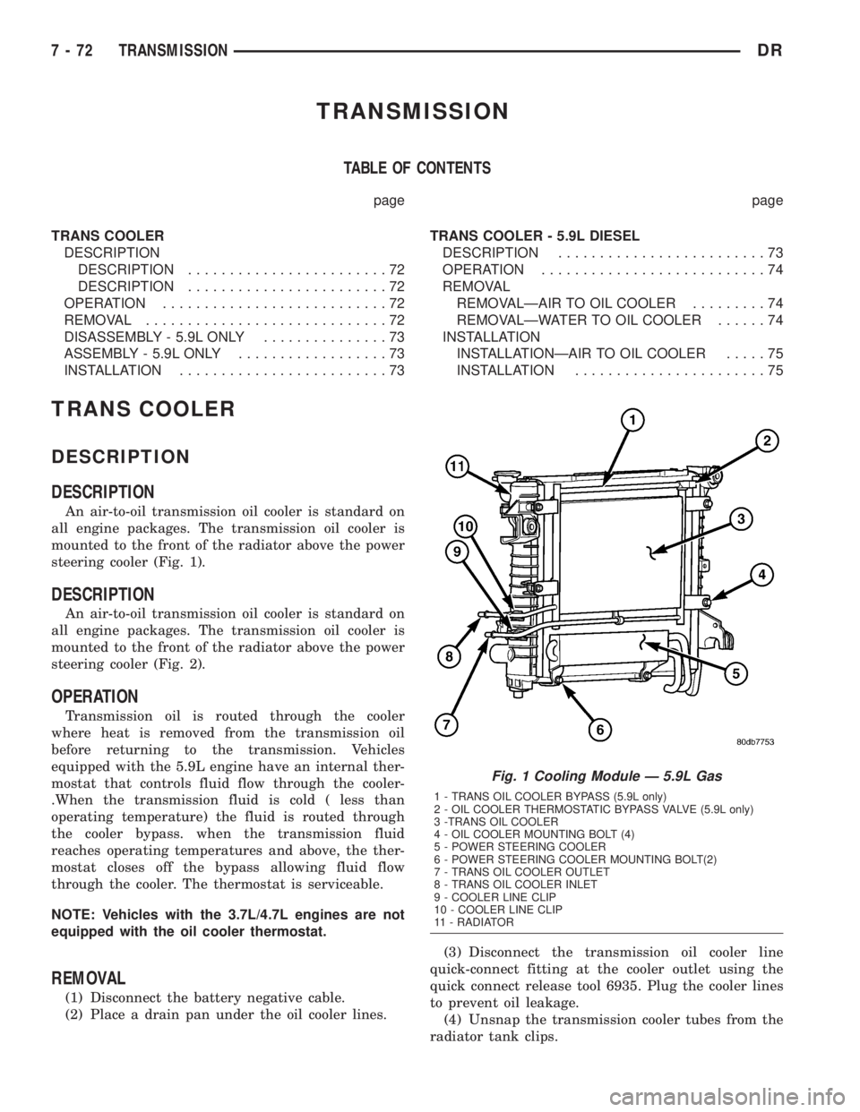
An air-to-oil transmission oil cooler is standard on
all engine packages. The transmission oil cooler is
mounted to the front of the radiator above the power
steering cooler (Fig. 1).
DESCRIPTION
An air-to-oil transmission oil cooler is standard on
all engine packages. The transmission oil cooler is
mounted to the front of the radiator above the power
steering cooler (Fig. 2).
OPERATION
Transmission oil is routed through the cooler
where heat is removed from the transmission oil
before returning to the transmission. Vehicles
equipped with the 5.9L engine have an internal ther-
mostat that controls fluid flow through the cooler-
.When the transmission fluid is cold ( less than
operating temperature) the fluid is routed through
the cooler bypass. when the transmission fluid
reaches operating temperatures and above, the ther-
mostat closes off the bypass allowing fluid flow
through the cooler. The thermostat is serviceable.
NOTE: Vehicles with the 3.7L/4.7L engines are not
equipped with the oil cooler thermostat.
REMOVAL
(1) Disconnect the battery negative cable.
(2) Place a drain pan under the oil cooler lines.(3) Disconnect the transmission oil cooler line
quick-connect fitting at the cooler outlet using the
quick connect release tool 6935. Plug the cooler lines
to prevent oil leakage.
(4) Unsnap the transmission cooler tubes from the
radiator tank clips.
Fig. 1 Cooling Module Ð 5.9L Gas
1 - TRANS OIL COOLER BYPASS (5.9L only)
2 - OIL COOLER THERMOSTATIC BYPASS VALVE (5.9L only)
3 -TRANS OIL COOLER
4 - OIL COOLER MOUNTING BOLT (4)
5 - POWER STEERING COOLER
6 - POWER STEERING COOLER MOUNTING BOLT(2)
7 - TRANS OIL COOLER OUTLET
8 - TRANS OIL COOLER INLET
9 - COOLER LINE CLIP
10 - COOLER LINE CLIP
11 - RADIATOR
7 - 72 TRANSMISSIONDR
Page 360 of 2895
(5) Remove the bolts attaching the transmission
cooler to the radiator.
(6) Remove oil cooler from the vehicle. Take care
not to damage the radiator core or transmission
cooler tubes.
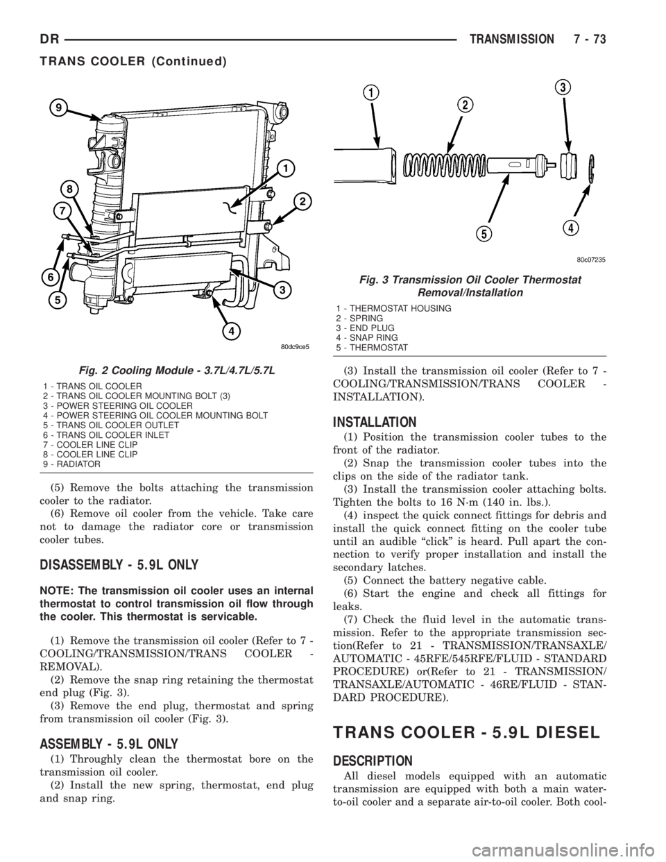
DISASSEMBLY - 5.9L ONLY
NOTE: The transmission oil cooler uses an internal
thermostat to control transmission oil flow through
the cooler. This thermostat is servicable.
(1) Remove the transmission oil cooler (Refer to 7 -
COOLING/TRANSMISSION/TRANS COOLER -
REMOVAL).
(2) Remove the snap ring retaining the thermostat
end plug (Fig. 3).
(3) Remove the end plug, thermostat and spring
from transmission oil cooler (Fig. 3).
ASSEMBLY - 5.9L ONLY
(1) Throughly clean the thermostat bore on the
transmission oil cooler.
(2) Install the new spring, thermostat, end plug
and snap ring.(3) Install the transmission oil cooler (Refer to 7 -
COOLING/TRANSMISSION/TRANS COOLER -
INSTALLATION).
INSTALLATION
(1) Position the transmission cooler tubes to the
front of the radiator.
(2) Snap the transmission cooler tubes into the
clips on the side of the radiator tank.
(3) Install the transmission cooler attaching bolts.
Tighten the bolts to 16 N´m (140 in. lbs.).
(4) inspect the quick connect fittings for debris and
install the quick connect fitting on the cooler tube
until an audible ªclickº is heard. Pull apart the con-
nection to verify proper installation and install the
secondary latches.
(5) Connect the battery negative cable.
(6) Start the engine and check all fittings for
leaks.
(7) Check the fluid level in the automatic trans-
mission. Refer to the appropriate transmission sec-
tion(Refer to 21 - TRANSMISSION/TRANSAXLE/
AUTOMATIC - 45RFE/545RFE/FLUID - STANDARD
PROCEDURE) or(Refer to 21 - TRANSMISSION/
TRANSAXLE/AUTOMATIC - 46RE/FLUID - STAN-
DARD PROCEDURE).
TRANS COOLER - 5.9L DIESEL
DESCRIPTION
All diesel models equipped with an automatic
transmission are equipped with both a main water-
to-oil cooler and a separate air-to-oil cooler. Both cool-
Fig. 2 Cooling Module - 3.7L/4.7L/5.7L
1 - TRANS OIL COOLER
2 - TRANS OIL COOLER MOUNTING BOLT (3)
3 - POWER STEERING OIL COOLER
4 - POWER STEERING OIL COOLER MOUNTING BOLT
5 - TRANS OIL COOLER OUTLET
6 - TRANS OIL COOLER INLET
7 - COOLER LINE CLIP
8 - COOLER LINE CLIP
9 - RADIATOR
Fig. 3 Transmission Oil Cooler Thermostat
Removal/Installation
1 - THERMOSTAT HOUSING
2 - SPRING
3 - END PLUG
4 - SNAP RING
5 - THERMOSTAT
DRTRANSMISSION 7 - 73
TRANS COOLER (Continued)
Page 679 of 2895
²Wipe-After-Wash Mode- When the control
knob on the control stalk of the multi-function switch
is depressed to the momentary Wash position for
more than about one-half second with the wiper sys-
tem turned Off, the washer pump/motor and the wip-
ers will operate for as long as the washer switch is
held closed up to about thirty seconds, then provide
several additional wipe cycles after the control knob
is released before parking the wiper blades near the
base of the windshield. If the control knob is held in
the depressed Wash position for more than about
thirty seconds, washer system operation will be sus-
pended until the control knob is released for about
two seconds then cycled back to the Wash position.
OPERATION
The wiper and washer system is designed to pro-
vide the vehicle operator with a convenient, safe, and
reliable means of maintaining visibility through the
windshield glass. The various components of this sys-
tem are designed to convert electrical energy pro-
duced by the vehicle electrical system into the
mechanical action of the wiper blades to wipe the
outside surface of the glass, as well as into the
hydraulic action of the washer system to apply
washer fluid stored in an on-board reservoir to the
area of the glass to be wiped. When combined, these
components provide the means to effectively main-
tain clear visibility for the vehicle operator by remov-
ing excess accumulations of rain, snow, bugs, mud, or
other minor debris from the outside windshield glass
surface that might be encountered while driving the
vehicle under numerous types of inclement operating
conditions.
The vehicle operator initiates all wiper and washer
system functions with the control knob on the end of
the control stalk of the multi-function switch that
extends from the left side of the steering column, just
below the steering wheel. Rotating the control knob
on the end of the control stalk, selects the Off, Delay,
Low, or High wiper system operating modes. In the
Delay mode, the control knob also allows the vehicle
operator to select from one of five intermittent wipe
Delay intervals. Depressing the control knob towards
the steering column actuates the momentary washer
system switch, which selects the Wash, Wipe-After-
Wash, and Pulse Wipe Modes depending upon when
and how long the switch is held closed. The multi-
function switch provides hard wired resistor multi-
plexed inputs to the instrument cluster for all of the
wiper and washer system functions. The instrument
cluster then sends electronic messages to the Front
Control Module (FCM) over the Programmable Com-
munications Interface (PCI) data bus requesting the
appropriate wiper and washer system operating
modes.Wiper and washer system operation are completely
controlled by the instrument cluster and FCM logic
circuits, and that logic will only allow these systems
to operate when the ignition switch is in the Acces-
sory or On positions. Battery current is directed from
a B(+) fuse in the Integrated Power Module (IPM) to
the wiper on/off relay and the wiper high/low relay in
the IPM through a fused B(+) circuit. The FCM uses
low side drivers to control wiper system operation by
energizing or de-energizing the wiper high/low and
wiper on/off relays. The FCM uses a high side driver
to control the operation of the washer pump motor
unit. The multi-function switch circuitry receives a
clean ground output from the instrument cluster on a
multi-function switch return circuit, then provides
resistor multiplexed inputs to the instrument cluster
on an intermittent wipe mux circuit to indicate the
selected wiper system mode and on a wash/beam
select mux circuit to indicate the selected washer sys-
tem mode.
The hard wired circuits and components of the
wiper and washer system may be diagnosed and
tested using conventional diagnostic tools and proce-
dures. However, conventional diagnostic methods
may not prove conclusive in the diagnosis of the
instrument cluster, the FCM, or the electronic mes-
sage inputs to or outputs from the instrument cluster
or FCM that control the wiper and washer system
operating modes. The most reliable, efficient, and
accurate means to diagnose the instrument cluster or
the FCM inputs and outputs related to the various
wiper and washer system operating modes requires
the use of a DRBIIItscan tool. Refer to the appro-
priate diagnostic information.
OPERATING MODES
Following are paragraphs that briefly describe the
operation of each of the wiper and washer system
operating modes.
CONTINUOUS WIPE MODE
When the Low position of the control knob on the
control stalk of the multi-function switch is selected
the instrument cluster sends an electronic wiper
switch low message to the FCM, then the FCM ener-
gizes the wiper on/off relay. This directs battery cur-
rent through the normally open contacts of the
energized wiper on/off relay and the normally closed
contacts of the de-energized wiper high/low relay to
the low speed brush of the wiper motor, causing the
wipers to cycle at low speed.
When the High position of the control knob is
selected the instrument cluster sends an electronic
wiper switch high message to the FCM, then the
FCM energizes both the wiper on/off relay and the
wiper high/low relay. This directs battery current
8R - 4 WIPERS/WASHERSDR
WIPERS/WASHERS (Continued)
Page 721 of 2895
Component Page
Overdrive Switch...................... 8W-31
Overhead Map/Reading Lamp............ 8W-44
Oxygen Sensors....................... 8W-30
Oxygen Sensor Downstream Relay........ 8W-30
Park Brake Switch.................... 8W-40
Park Lamp Relay................... 8W-50, 52
Park/Turn Signal Lamps............. 8W-50, 52
Passenger Airbag On/Off Switch.......... 8W-43
Blend Door Actuators.................. 8W-42
Passenger Lumbar Switch............... 8W-63
Power Mirrors........................ 8W-62
Power Outlet......................... 8W-41
Power Outlet-Console.................. 8W-41
Power Seat Motors.................... 8W-63
Power Seat Switches................... 8W-63
Power Steering Pressure Switch.......... 8W-30
Power Window Circuit Breaker........... 8W-10
Power Window Motors.................. 8W-60
Power Window Switches................ 8W-60
Powertrain Control Module.............. 8W-30
PTCs............................... 8W-10
PTO Switch.......................... 8W-30
Radio............................... 8W-47
Recirculation Door Actuator............. 8W-42
Red Brake Warning Indicator Switch . . . 8W-34, 35
Remote Radio Switches................. 8W-47
Splices.............................. 8W-70
Seat Belt Pretensioners................. 8W-43
Seat Belt Switch-Driver................ 8W-40
Seat Belt Tensioner Reducer............. 8W-40
Seat Heater Interface Module............ 8W-63
Sentry Key Immobilizer Module.......... 8W-39
Spare Relay.......................... 8W-10
Speakers............................ 8W-47Component Page
Speed Control Servo................... 8W-33
Speed Control Switches................. 8W-33
Starter Motor Relay................... 8W-21
Starter Motor.................... 8W-21, 21-3
Tail/Stop Lamps...................... 8W-52
Tail/Stop/Turn Signal Lamps.......... 8W-51, 52
Tail/Turn Lamps...................... 8W-52
Tailgate Lamp Assembly................ 8W-51
Throttle Position Sensor................ 8W-30
Throttle Position Switch................ 8W-30
Trailer Tow Connector.................. 8W-54
Trailer Tow Connector-Add On........... 8W-54
Trailer Tow Left Turn Relay............. 8W-54
Trailer Tow Right Turn Relay............ 8W-54
Transfer Case Control Module............ 8W-31
Transfer Case Mode Sensor.............. 8W-31
Transfer Case Selector Switch............ 8W-31
Transfer Case Shift Motor............... 8W-31
Transmission Control Module............ 8W-31
Transmission Control Relay............. 8W-31
Transmission Range Sensor.............. 8W-31
Transmission Solenoid Assembly.......... 8W-31
Transmission Solenoid/TRS Assembly...... 8W-31
Underhood Lamp...................... 8W-44
Vacuum Pump........................ 8W-30
Vehicle Speed Sensor................... 8W-30
Vistronic Fan Drive.................... 8W-30
Washer Fluid Level Switch.............. 8W-53
Washer Pump Motor-Front.............. 8W-53
Water In Fuel Sensor.................. 8W-30
Wheel Speed Sensors................... 8W-35
Wiper High/Low Relay................. 8W-53
Wiper Motor-Front.................... 8W-53
8W - 02 - 2 8W-02 COMPONENT INDEXDR
Page 1435 of 2895
STANDARD PROCEDURE
STANDARD PROCEDURE - REPAIR DAMAGED
OR WORN THREADS
CAUTION: Be sure that the tapped holes maintain
the original center line.
Damaged or worn threads can be repaired. Essen-
tially, this repair consists of:
²Drilling out worn or damaged threads.
²Tapping the hole with a special Heli-Coil Tap, or
equivalent.
²Installing an insert into the tapped hole to bring
the hole back to its original thread size.
STANDARD PROCEDUREÐHYDROSTATIC
LOCK
CAUTION: DO NOT use the starter motor to rotate
the crankshaft. Severe damage could occur.
When an engine is suspected of hydrostatic lock
(regardless of what caused the problem), follow the
steps below.
(1) Perform the Fuel Pressure Release Procedure
(Refer to 14 - FUEL SYSTEM/FUEL DELIVERY -
STANDARD PROCEDURE).
(2) Disconnect the negative cable(s) from the bat-
tery.
(3) Inspect air cleaner, induction system, and
intake manifold to ensure system is dry and clear of
foreign material.
(4) Place a shop towel around the spark plugs to
catch any fluid that may possibly be under pressure
in the cylinder head. Remove the spark plugs.
(5) With all spark plugs removed, rotate the crank-
shaft using a breaker bar and socket.
(6) Identify the fluid in the cylinders (coolant, fuel,
oil, etc.).
(7) Be sure all fluid has been removed from the
cylinders.
(8) Repair engine or components as necessary to
prevent this problem from occurring again.
(9) Squirt a small amount of engine oil into the
cylinders to lubricate the walls. This will prevent
damage on restart.
(10) Install new spark plugs. Tighten the spark
plugs to 41 N´m (30 ft. lbs.) torque.
(11) Drain engine oil. Remove and discard the oil
filter.
(12) Install the drain plug. Tighten the plug to 34
N´m (25 ft. lbs.) torque.
(13) Install a new oil filter.(14) Fill engine crankcase with the specified
amount and grade of oil. (Refer to LUBRICATION &
MAINTENANCE - SPECIFICATIONS).
(15) Connect the negative cable(s) to the battery.
(16) Start the engine and check for any leaks.
REMOVAL
(1) Disconnect the battery negative cable.
(2) Remove the air cleaner resonator and duct
work as an assembly.
(3) Drain cooling system (Refer to 7 - COOLING -
STANDARD PROCEDURE).
(4) Remove the accessory drive belt (Refer to 7 -
COOLING/ACCESSORY DRIVE/DRIVE BELTS -
REMOVAL).
(5) Remove the viscous fan/drive (Refer to 7 -
COOLING/ENGINE/RADIATOR FAN - REMOVAL).
(6) Remove radiator (Refer to 7 - COOLING/EN-
GINE/RADIATOR - REMOVAL).
(7) Remove the upper crossmember and top core
support.
NOTE: It is not necessary to drain A/C system for
engine removal.
(8) Remove the A/C compressor with the lines
attached. Secure compressor out of the way.
(9) Remove generator assembly (Refer to 8 -
ELECTRICAL/CHARGING/GENERATOR - REMOV-
AL).
(10) Perform the Fuel System Pressure Release
procedure (Refer to 14 - FUEL SYSTEM/FUEL
DELIVERY - STANDARD PROCEDURE).
(11) Remove the intake manifold and IAFM as an
assembly(Refer to 9 - ENGINE/MANIFOLDS/IN-
TAKE MANIFOLD - REMOVAL).
(12) Disconnect the heater hoses.
NOTE: It is not necessary to disconnect P/S hoses
from pump, for P/S pump removal.
(13) Remove the power steering pump and set
aside.
(14) Disconnect the fuel supply line (Refer to 14 -
FUEL SYSTEM/FUEL DELIVERY/QUICK CON-
NECT FITTING - STANDARD PROCEDURE).
(15) Raise and support the vehicle on a hoist and
drain the engine oil.
(16) Remove engine front mount thru-bolt nuts.
(17) Disconnect the transmission oil cooler lines
from their retainers at the oil pan bolts.
(18) Disconnect exhaust pipe at manifolds.
(19) Disconnect the starter wires. Remove starter
motor (Refer to 8 - ELECTRICAL/STARTING/
STARTER MOTOR - REMOVAL).
9 - 186 ENGINE - 5.7LDR
ENGINE - 5.7L (Continued)
Page 1436 of 2895
(20) Remove the structural dust cover and trans-
mission inspection cover,(Refer to 9 - ENGINE/EN-
GINE BLOCK/STRUCTURAL COVER - REMOVAL).
(21) Remove drive plate to converter bolts (Auto-
matic transmission equipped vehicles).
(22) Remove transmission bell housing to engine
block bolts.
(23) Lower the vehicle.
(24) Install engine lift fixture, special tool # 8984.
(25) Separate engine from transmission, remove
engine from vehicle, and install engine assembly on a
repair stand.
INSTALLATION
(1) Install engine lift fixture Special tool # 8984.
(2) Position the engine in the engine compartment.
(3) Lower engine into compartment and align
engine with transmission:
²Manual Transmission: Align clutch disc assem-
bly (if disturbed). Install transmission input shaft
into clutch disc while mating engine and transmis-
sion surfaces. Install two transmission to engine
block mounting bolts finger tight.
²Automatic Transmission: Mate engine and trans-
mission and install two transmission to engine block
mounting bolts finger tight.
(4) Position the thru-bolt into the support cushion
brackets.
(5) Lower engine assembly until engine mount
through bolts rest in mount perches.
(6) Install remaining transmission to engine block
mounting bolts and tighten.
(7) Tighten engine mount through bolts.
(8) Install drive plate to torque converter bolts.
(Automatic transmission models)
(9) Install the structural dust cover and transmis-
sion dust cover,(Refer to 9 - ENGINE/ENGINE
BLOCK/STRUCTURAL COVER - INSTALLATION) .
(10) Install the starter and connect the starter
wires (Refer to 8 - ELECTRICAL/STARTING/
STARTER MOTOR - INSTALLATION).
(11) Install exhaust pipe to manifold.(12) Lower the vehicle.
(13) Remove engine lift fixture, special tool # 8984.
(14) Connect the fuel supply line (Refer to 14 -
FUEL SYSTEM/FUEL DELIVERY/QUICK CON-
NECT FITTING - STANDARD PROCEDURE).
(15) Reinstall the power steering pump.
(16) Connect the heater hoses.
(17) Install the intake manifold.
(18) Using a new gasket, install throttle body
(Refer to 14 - FUEL SYSTEM/FUEL INJECTION/
THROTTLE BODY - INSTALLATION).
(19) Install the generator and wire connections
(Refer to 8 - ELECTRICAL/CHARGING/GENERA-
TOR - INSTALLATION).
(20) Install a/c compressor and lines (Refer to 24 -
HEATING & AIR CONDITIONING/PLUMBING/A/C
COMPRESSOR - INSTALLATION).
(21) Install the accessory drive belt (Refer to 7 -
COOLING/ACCESSORY DRIVE/DRIVE BELTS -
INSTALLATION).
(22) Install upper radiator support crossmember.
(23) Install radiator (Refer to 7 - COOLING/EN-
GINE/RADIATOR - INSTALLATION).
(24) Connect the radiator lower hose.
(25) Connect the transmission oil cooler lines to
the radiator.
(26) Install the fan shroud.
(27) Install the fan (Refer to 7 - COOLING/EN-
GINE/RADIATOR FAN - INSTALLATION).
(28) Connect the radiator upper hose.
(29) Install the washer bottle.
(30) Connect the transmission cooler lines.
(31) Install the air cleaner resonator and duct
work..
(32) Add engine oil to crankcase (Refer to LUBRI-
CATION & MAINTENANCE/FLUID TYPES - SPEC-
IFICATIONS).
(33) Fill cooling system (Refer to 7 - COOLING -
STANDARD PROCEDURE).
(34) Connect battery negative cable.
(35) Start engine and inspect for leaks.
(36) Road test vehicle.
DRENGINE - 5.7L 9 - 187
ENGINE - 5.7L (Continued)