check engine DODGE RAM 2003 Service Repair Manual
[x] Cancel search | Manufacturer: DODGE, Model Year: 2003, Model line: RAM, Model: DODGE RAM 2003Pages: 2895, PDF Size: 83.15 MB
Page 1497 of 2895
ing stones. A true and complete surface must be
obtained.
(2) Measure the concentricity of valve seat using a
dial indicator. Total runout should not exceed 0.051
mm (0.002 in.) total indicator reading.
(3) Inspect the valve seat with Prussian blue, to
determine where the valve contacts the seat. To do
this, coat valve seat LIGHTLY with Prussian blue
then set valve in place. Rotate the valve with light
pressure. If the blue is transferred to the center of
valve face, contact is satisfactory. If the blue is trans-
ferred to the top edge of valve face, lower valve seat
with a 15É stone. If the blue is transferred to bottom
edge of valve face raise valve seat with a 60É stone.
(4) When seat is properly positioned the width of
intake seats should be 1.016-1.524 mm (0.040-0.060
in.). The width of the exhaust seats should be 1.524-
2.032 mm (0.060-0.080 in.).
VALVE SPRINGS
Whenever valves have been removed for inspection,
reconditioning or replacement, valve springs should
be tested. As an example the compression length of
the spring to be tested is 1-5/16 in.. Turn table of
Universal Valve Spring Tester Tool until surface is in
line with the 1-5/16 in. mark on the threaded stud.
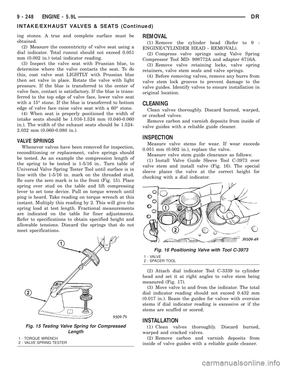
Be sure the zero mark is to the front (Fig. 15). Place
spring over stud on the table and lift compressing
lever to set tone device. Pull on torque wrench until
ping is heard. Take reading on torque wrench at this
instant. Multiply this reading by 2. This will give the
spring load at test length. Fractional measurements
are indicated on the table for finer adjustments.
Refer to specifications to obtain specified height and
allowable tensions. Discard the springs that do not
meet specifications.
REMOVAL
(1) Remove the cylinder head (Refer to 9 -
ENGINE/CYLINDER HEAD - REMOVAL).
(2) Compress valve springs using Valve Spring
Compressor Tool MD- 998772A and adapter 6716A.
(3) Remove valve retaining locks, valve spring
retainers, valve stem seals and valve springs.
(4) Before removing valves, remove any burrs from
valve stem lock grooves to prevent damage to the
valve guides. Identify valves to ensure installation in
original location.
CLEANING
Clean valves thoroughly. Discard burned, warped,
or cracked valves.
Remove carbon and varnish deposits from inside of
valve guides with a reliable guide cleaner.
INSPECTION
Measure valve stems for wear. If wear exceeds
0.051 mm (0.002 in.), replace the valve.
Measure valve stem guide clearance as follows:
(1) Install Valve Guide Sleeve Tool C-3973 over
valve stem and install valve (Fig. 16). The special
sleeve places the valve at the correct height for
checking with a dial indicator.
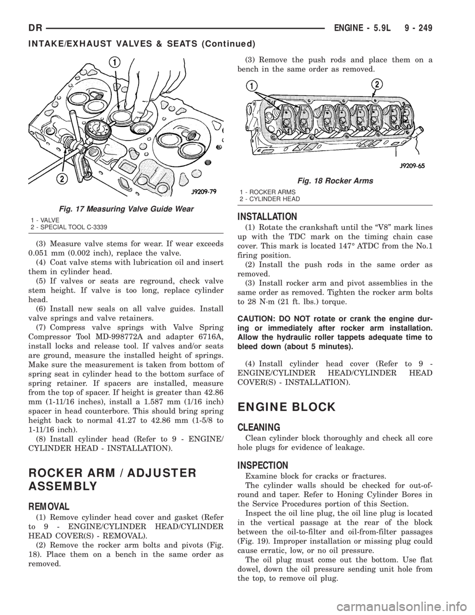
(2) Attach dial indicator Tool C-3339 to cylinder
head and set it at right angles to valve stem being
measured (Fig. 17).
(3) Move valve to and from the indicator. The total
dial indicator reading should not exceed 0.432 mm
(0.017 in.). Ream the guides for valves with oversize
stems if dial indicator reading is excessive or if the
stems are scuffed or scored.
INSTALLATION
(1) Clean valves thoroughly. Discard burned,
warped and cracked valves.
(2) Remove carbon and varnish deposits from
inside of valve guides with a reliable guide cleaner.Fig. 15 Testing Valve Spring for Compressed
Length
1 - TORQUE WRENCH
2 - VALVE SPRING TESTER
Fig. 16 Positioning Valve with Tool C-3973
1 - VALVE
2 - SPACER TOOL
9 - 248 ENGINE - 5.9LDR
INTAKE/EXHAUST VALVES & SEATS (Continued)
Page 1498 of 2895
(3) Measure valve stems for wear. If wear exceeds
0.051 mm (0.002 inch), replace the valve.
(4) Coat valve stems with lubrication oil and insert
them in cylinder head.
(5) If valves or seats are reground, check valve
stem height. If valve is too long, replace cylinder
head.
(6) Install new seals on all valve guides. Install
valve springs and valve retainers.
(7) Compress valve springs with Valve Spring
Compressor Tool MD-998772A and adapter 6716A,
install locks and release tool. If valves and/or seats
are ground, measure the installed height of springs.
Make sure the measurement is taken from bottom of
spring seat in cylinder head to the bottom surface of
spring retainer. If spacers are installed, measure
from the top of spacer. If height is greater than 42.86
mm (1-11/16 inches), install a 1.587 mm (1/16 inch)
spacer in head counterbore. This should bring spring
height back to normal 41.27 to 42.86 mm (1-5/8 to
1-11/16 inch).
(8) Install cylinder head (Refer to 9 - ENGINE/
CYLINDER HEAD - INSTALLATION).
ROCKER ARM / ADJUSTER
ASSEMBLY
REMOVAL
(1) Remove cylinder head cover and gasket (Refer
to 9 - ENGINE/CYLINDER HEAD/CYLINDER
HEAD COVER(S) - REMOVAL).
(2) Remove the rocker arm bolts and pivots (Fig.
18). Place them on a bench in the same order as
removed.(3) Remove the push rods and place them on a
bench in the same order as removed.
INSTALLATION
(1) Rotate the crankshaft until the ªV8º mark lines
up with the TDC mark on the timing chain case
cover. This mark is located 147É ATDC from the No.1
firing position.
(2) Install the push rods in the same order as
removed.
(3) Install rocker arm and pivot assemblies in the
same order as removed. Tighten the rocker arm bolts
to 28 N´m (21 ft. lbs.) torque.
CAUTION: DO NOT rotate or crank the engine dur-
ing or immediately after rocker arm installation.
Allow the hydraulic roller tappets adequate time to
bleed down (about 5 minutes).
(4) Install cylinder head cover (Refer to 9 -
ENGINE/CYLINDER HEAD/CYLINDER HEAD
COVER(S) - INSTALLATION).
ENGINE BLOCK
CLEANING
Clean cylinder block thoroughly and check all core
hole plugs for evidence of leakage.
INSPECTION
Examine block for cracks or fractures.
The cylinder walls should be checked for out-of-
round and taper. Refer to Honing Cylinder Bores in
the Service Procedures portion of this Section.
Inspect the oil line plug, the oil line plug is located
in the vertical passage at the rear of the block
between the oil-to-filter and oil-from-filter passages
(Fig. 19). Improper installation or missing plug could
cause erratic, low, or no oil pressure.
The oil plug must come out the bottom. Use flat
dowel, down the oil pressure sending unit hole from
the top, to remove oil plug.
Fig. 17 Measuring Valve Guide Wear
1 - VALVE
2 - SPECIAL TOOL C-3339
Fig. 18 Rocker Arms
1 - ROCKER ARMS
2 - CYLINDER HEAD
DRENGINE - 5.9L 9 - 249
INTAKE/EXHAUST VALVES & SEATS (Continued)
Page 1500 of 2895
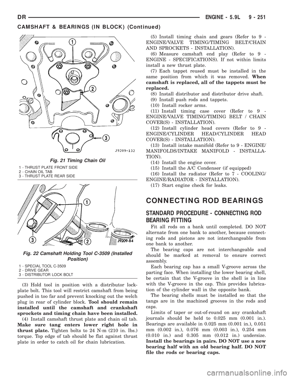
(3) Hold tool in position with a distributor lock-
plate bolt. This tool will restrict camshaft from being
pushed in too far and prevent knocking out the welch
plug in rear of cylinder block.Tool should remain
installed until the camshaft and crankshaft
sprockets and timing chain have been installed.
(4) Install camshaft thrust plate and chain oil tab.
Make sure tang enters lower right hole in
thrust plate.Tighten bolts to 24 N´m (210 in. lbs.)
torque. Top edge of tab should be flat against thrust
plate in order to catch oil for chain lubrication.(5) Install timing chain and gears (Refer to 9 -
ENGINE/VALVE TIMING/TIMING BELT/CHAIN
AND SPROCKETS - INSTALLATION).
(6) Measure camshaft end play (Refer to 9 -
ENGINE - SPECIFICATIONS). If not within limits
install a new thrust plate.
(7) Each tappet reused must be installed in the
same position from which it was removed.When
camshaft is replaced, all of the tappets must be
replaced.
(8) Install distributor and distributor drive shaft.
(9) Install push rods and tappets.
(10) Install rocker arms.
(11) Install timing case cover (Refer to 9 -
ENGINE/VALVE TIMING/TIMING BELT / CHAIN
COVER(S) - INSTALLATION).
(12) Install cylinder head covers (Refer to 9 -
ENGINE/CYLINDER HEAD/CYLINDER HEAD
COVER(S) - INSTALLATION).
(13) Install intake manifold (Refer to 9 - ENGINE/
MANIFOLDS/INTAKE MANIFOLD - INSTALLA-
TION).
(14) Install the engine cover.
(15) Install the A/C Condenser (if equipped)
(16) Install the radiator (Refer to 7 - COOLING/
ENGINE/RADIATOR - INSTALLATION).
(17) Start engine check for leaks.
CONNECTING ROD BEARINGS
STANDARD PROCEDURE - CONNECTING ROD
BEARING FITTING
Fit all rods on a bank until completed. DO NOT
alternate from one bank to another, because connect-
ing rods and pistons are not interchangeable from
one bank to another.
The bearing caps are not interchangeable and
should be marked at removal to ensure correct
assembly.
Each bearing cap has a small V-groove across the
parting face. When installing the lower bearing shell,
be certain that the V-groove in the shell is in line
with the V-groove in the cap. This provides lubrica-
tion of the cylinder wall in the opposite bank.
The bearing shells must be installed so that the
tangs are in the machined grooves in the rods and
caps.
Limits of taper or out-of-round on any crankshaft
journals should be held to 0.025 mm (0.001 in.).
Bearings are available in 0.025 mm (0.001 in.), 0.051
mm (0.002 in.), 0.076 mm (0.003 in.), 0.254 mm
(0.010 in.) and 0.305 mm (0.012 in.) undersize.
Install the bearings in pairs. DO NOT use a new
bearing half with an old bearing half. DO NOT
file the rods or bearing caps.
Fig. 21 Timing Chain Oil
1 - THRUST PLATE FRONT SIDE
2 - CHAIN OIL TAB
3 - THRUST PLATE REAR SIDE
Fig. 22 Camshaft Holding Tool C-3509 (Installed
Position)
1 - SPECIAL TOOL C-3509
2 - DRIVE GEAR
3 - DISTRIBUTOR LOCK BOLT
DRENGINE - 5.9L 9 - 251
CAMSHAFT & BEARINGS (IN BLOCK) (Continued)
Page 1503 of 2895
Main Bearing Undersize Availability List
²0.25 mm (0.001 inch)
²0.051 mm (0.002 inch)
²0.076 mm (0.003 inch)
²0.254 mm (0.010 inch)
²0.305 mm (0.012 inch)
REMOVAL
(1) Remove the oil pan (Refer to 9 - ENGINE/LU-
BRICATION/OIL PAN - REMOVAL).
(2) Remove the oil pump from the rear main bear-
ing cap (Refer to 9 - ENGINE/LUBRICATION/OIL
PUMP - REMOVAL).
(3) Identify bearing caps before removal. Remove
bearing caps one at a time.
(4) Remove upper half of bearing by inserting
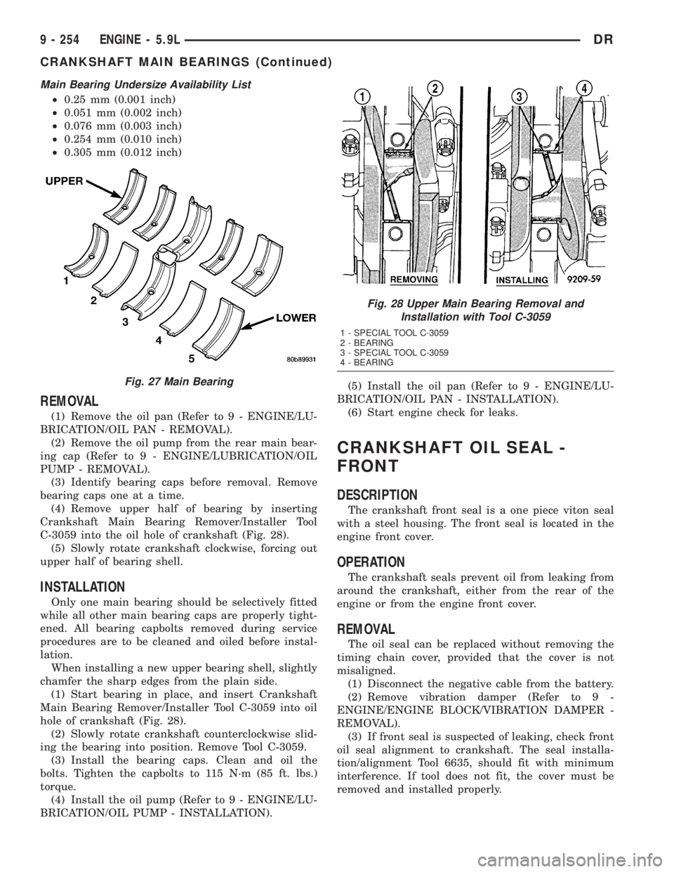
Crankshaft Main Bearing Remover/Installer Tool
C-3059 into the oil hole of crankshaft (Fig. 28).
(5) Slowly rotate crankshaft clockwise, forcing out
upper half of bearing shell.
INSTALLATION
Only one main bearing should be selectively fitted
while all other main bearing caps are properly tight-
ened. All bearing capbolts removed during service
procedures are to be cleaned and oiled before instal-
lation.
When installing a new upper bearing shell, slightly
chamfer the sharp edges from the plain side.
(1) Start bearing in place, and insert Crankshaft
Main Bearing Remover/Installer Tool C-3059 into oil
hole of crankshaft (Fig. 28).
(2) Slowly rotate crankshaft counterclockwise slid-
ing the bearing into position. Remove Tool C-3059.
(3) Install the bearing caps. Clean and oil the
bolts. Tighten the capbolts to 115 N´m (85 ft. lbs.)
torque.
(4) Install the oil pump (Refer to 9 - ENGINE/LU-
BRICATION/OIL PUMP - INSTALLATION).(5) Install the oil pan (Refer to 9 - ENGINE/LU-
BRICATION/OIL PAN - INSTALLATION).
(6) Start engine check for leaks.
CRANKSHAFT OIL SEAL -
FRONT
DESCRIPTION
The crankshaft front seal is a one piece viton seal
with a steel housing. The front seal is located in the
engine front cover.
OPERATION
The crankshaft seals prevent oil from leaking from
around the crankshaft, either from the rear of the
engine or from the engine front cover.
REMOVAL
The oil seal can be replaced without removing the
timing chain cover, provided that the cover is not
misaligned.
(1) Disconnect the negative cable from the battery.
(2) Remove vibration damper (Refer to 9 -
ENGINE/ENGINE BLOCK/VIBRATION DAMPER -
REMOVAL).
(3) If front seal is suspected of leaking, check front
oil seal alignment to crankshaft. The seal installa-
tion/alignment Tool 6635, should fit with minimum
interference. If tool does not fit, the cover must be
removed and installed properly.
Fig. 27 Main Bearing
Fig. 28 Upper Main Bearing Removal and
Installation with Tool C-3059
1 - SPECIAL TOOL C-3059
2 - BEARING
3 - SPECIAL TOOL C-3059
4 - BEARING
9 - 254 ENGINE - 5.9LDR
CRANKSHAFT MAIN BEARINGS (Continued)
Page 1505 of 2895
lower seal. The lower seal half can be installed only
with the rear main bearing cap removed.
UPPER SEAL ÐCRANKSHAFT REMOVED
(1) Remove the crankshaft (Refer to 9 - ENGINE/
ENGINE BLOCK/CRANKSHAFT - REMOVAL). Dis-
card the old upper seal.
UPPER SEALÐCRANKSHAFT INSTALLED
(1) Remove the oil pan (Refer to 9 - ENGINE/LU-
BRICATION/OIL PAN - REMOVAL).
(2) Remove the oil pump (Refer to 9 - ENGINE/
LUBRICATION/OIL PUMP - REMOVAL).
(3) Remove the rear main bearing cap. Remove
and discard the old lower oil seal.
(4) Carefully remove and discard the old upper oil
seal.
LOWER SEAL
(1) Remove the oil pan (Refer to 9 - ENGINE/LU-
BRICATION/OIL PAN - REMOVAL).
(2) Remove the oil pump (Refer to 9 - ENGINE/
LUBRICATION/OIL PUMP - REMOVAL).
(3) Remove the rear main bearing cap and discard
the old lower seal.
INSTALLATION
The service seal is a two piece, Viton seal. The
upper seal half can be installed with crankshaft
removed from engine or with crankshaft installed.
When a new upper seal is installed, install a new
lower seal. The lower seal half can be installed only
with the rear main bearing cap removed.
UPPER SEAL ÐCRANKSHAFT REMOVED
(1) Clean the cylinder block rear cap mating sur-
face. Be sure the seal groove is free of debris. Check
for burrs at the oil hole on the cylinder block mating
surface to rear cap.
(2) Lightly oil the new upper seal lips with engine
oil.
(3) Install the new upper rear bearing oil seal with
the white paint facing toward the rear of the engine.
(4) Position the crankshaft into the cylinder block.
(5)
Lightly oil the new lower seal lips with engine oil.
(6) Install the new lower rear bearing oil seal into
the bearing cap with the white paint facing towards
the rear of the engine.
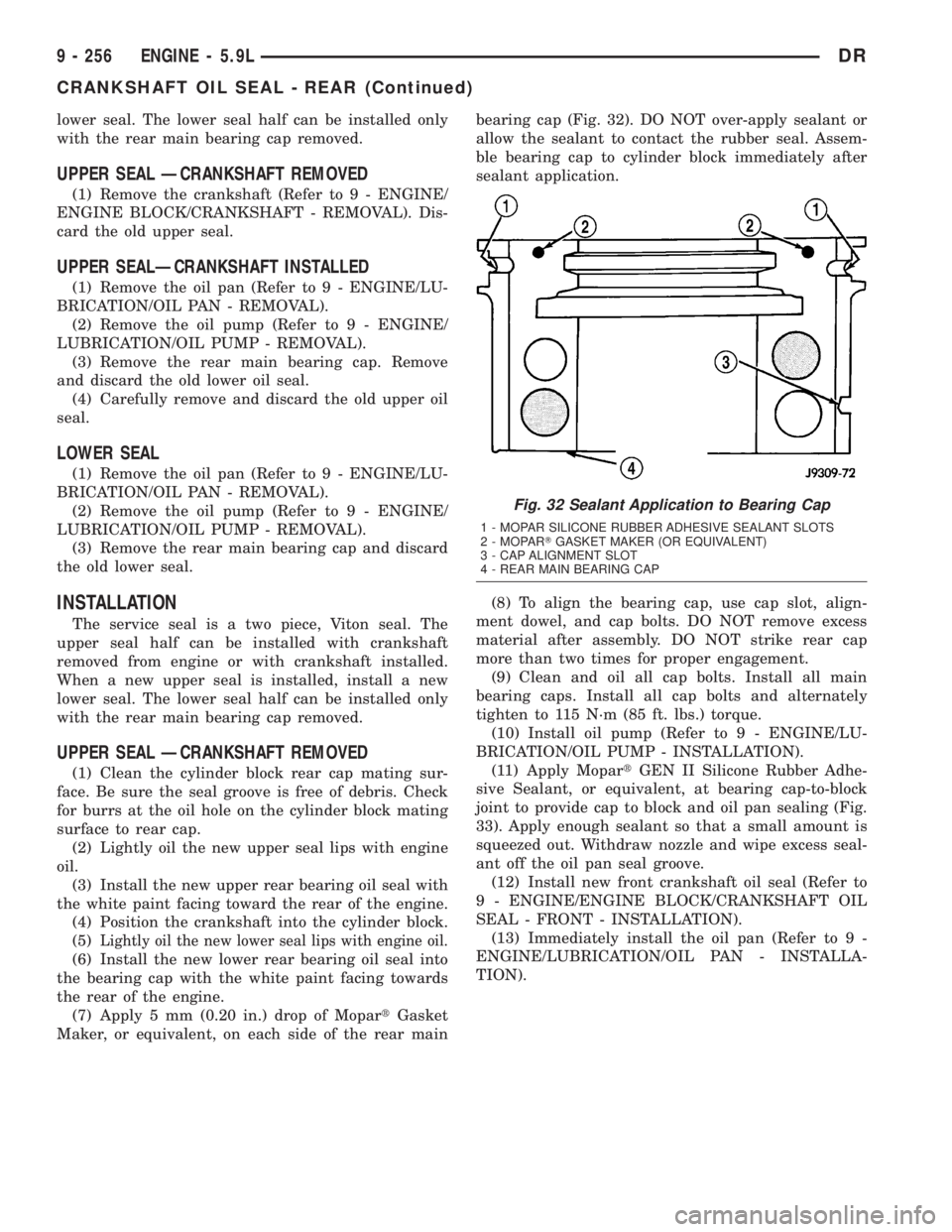
(7) Apply 5 mm (0.20 in.) drop of MopartGasket
Maker, or equivalent, on each side of the rear mainbearing cap (Fig. 32). DO NOT over-apply sealant or
allow the sealant to contact the rubber seal. Assem-
ble bearing cap to cylinder block immediately after
sealant application.
(8) To align the bearing cap, use cap slot, align-
ment dowel, and cap bolts. DO NOT remove excess
material after assembly. DO NOT strike rear cap
more than two times for proper engagement.
(9) Clean and oil all cap bolts. Install all main
bearing caps. Install all cap bolts and alternately
tighten to 115 N´m (85 ft. lbs.) torque.
(10) Install oil pump (Refer to 9 - ENGINE/LU-
BRICATION/OIL PUMP - INSTALLATION).
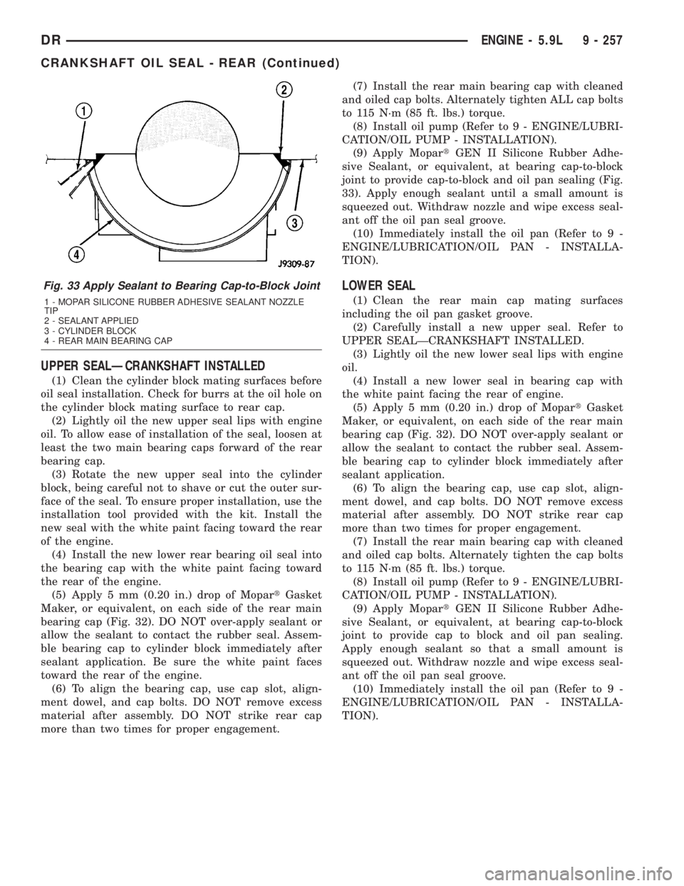
(11) Apply MopartGEN II Silicone Rubber Adhe-
sive Sealant, or equivalent, at bearing cap-to-block
joint to provide cap to block and oil pan sealing (Fig.
33). Apply enough sealant so that a small amount is
squeezed out. Withdraw nozzle and wipe excess seal-
ant off the oil pan seal groove.
(12) Install new front crankshaft oil seal (Refer to
9 - ENGINE/ENGINE BLOCK/CRANKSHAFT OIL
SEAL - FRONT - INSTALLATION).
(13) Immediately install the oil pan (Refer to 9 -
ENGINE/LUBRICATION/OIL PAN - INSTALLA-
TION).
Fig. 32 Sealant Application to Bearing Cap
1 - MOPAR SILICONE RUBBER ADHESIVE SEALANT SLOTS
2 - MOPARTGASKET MAKER (OR EQUIVALENT)
3 - CAP ALIGNMENT SLOT
4 - REAR MAIN BEARING CAP
9 - 256 ENGINE - 5.9LDR
CRANKSHAFT OIL SEAL - REAR (Continued)
Page 1506 of 2895
UPPER SEALÐCRANKSHAFT INSTALLED
(1) Clean the cylinder block mating surfaces before
oil seal installation. Check for burrs at the oil hole on
the cylinder block mating surface to rear cap.
(2) Lightly oil the new upper seal lips with engine
oil. To allow ease of installation of the seal, loosen at
least the two main bearing caps forward of the rear
bearing cap.
(3) Rotate the new upper seal into the cylinder
block, being careful not to shave or cut the outer sur-
face of the seal. To ensure proper installation, use the
installation tool provided with the kit. Install the
new seal with the white paint facing toward the rear
of the engine.
(4) Install the new lower rear bearing oil seal into
the bearing cap with the white paint facing toward
the rear of the engine.
(5) Apply 5 mm (0.20 in.) drop of MopartGasket
Maker, or equivalent, on each side of the rear main
bearing cap (Fig. 32). DO NOT over-apply sealant or
allow the sealant to contact the rubber seal. Assem-
ble bearing cap to cylinder block immediately after
sealant application. Be sure the white paint faces
toward the rear of the engine.
(6) To align the bearing cap, use cap slot, align-
ment dowel, and cap bolts. DO NOT remove excess
material after assembly. DO NOT strike rear cap
more than two times for proper engagement.(7) Install the rear main bearing cap with cleaned
and oiled cap bolts. Alternately tighten ALL cap bolts
to 115 N´m (85 ft. lbs.) torque.
(8) Install oil pump (Refer to 9 - ENGINE/LUBRI-
CATION/OIL PUMP - INSTALLATION).
(9) Apply MopartGEN II Silicone Rubber Adhe-
sive Sealant, or equivalent, at bearing cap-to-block
joint to provide cap-to-block and oil pan sealing (Fig.
33). Apply enough sealant until a small amount is
squeezed out. Withdraw nozzle and wipe excess seal-
ant off the oil pan seal groove.
(10) Immediately install the oil pan (Refer to 9 -
ENGINE/LUBRICATION/OIL PAN - INSTALLA-
TION).
LOWER SEAL
(1) Clean the rear main cap mating surfaces
including the oil pan gasket groove.
(2) Carefully install a new upper seal. Refer to
UPPER SEALÐCRANKSHAFT INSTALLED.
(3) Lightly oil the new lower seal lips with engine
oil.
(4) Install a new lower seal in bearing cap with
the white paint facing the rear of engine.
(5) Apply 5 mm (0.20 in.) drop of MopartGasket
Maker, or equivalent, on each side of the rear main
bearing cap (Fig. 32). DO NOT over-apply sealant or
allow the sealant to contact the rubber seal. Assem-
ble bearing cap to cylinder block immediately after
sealant application.
(6) To align the bearing cap, use cap slot, align-
ment dowel, and cap bolts. DO NOT remove excess
material after assembly. DO NOT strike rear cap
more than two times for proper engagement.
(7) Install the rear main bearing cap with cleaned
and oiled cap bolts. Alternately tighten the cap bolts
to 115 N´m (85 ft. lbs.) torque.
(8) Install oil pump (Refer to 9 - ENGINE/LUBRI-
CATION/OIL PUMP - INSTALLATION).
(9) Apply MopartGEN II Silicone Rubber Adhe-
sive Sealant, or equivalent, at bearing cap-to-block
joint to provide cap to block and oil pan sealing.
Apply enough sealant so that a small amount is
squeezed out. Withdraw nozzle and wipe excess seal-
ant off the oil pan seal groove.
(10) Immediately install the oil pan (Refer to 9 -
ENGINE/LUBRICATION/OIL PAN - INSTALLA-
TION).
Fig. 33 Apply Sealant to Bearing Cap-to-Block Joint
1 - MOPAR SILICONE RUBBER ADHESIVE SEALANT NOZZLE
TIP
2 - SEALANT APPLIED
3 - CYLINDER BLOCK
4 - REAR MAIN BEARING CAP
DRENGINE - 5.9L 9 - 257
CRANKSHAFT OIL SEAL - REAR (Continued)
Page 1507 of 2895
DISTRIBUTOR BUSHING
REMOVAL
(1) Remove distributor (Refer to 8 - ELECTRICAL/
IGNITION CONTROL/DISTRIBUTOR - REMOVAL).
(2) Remove the intake manifold (Refer to 9 -
ENGINE/MANIFOLDS/INTAKE MANIFOLD -
REMOVAL).
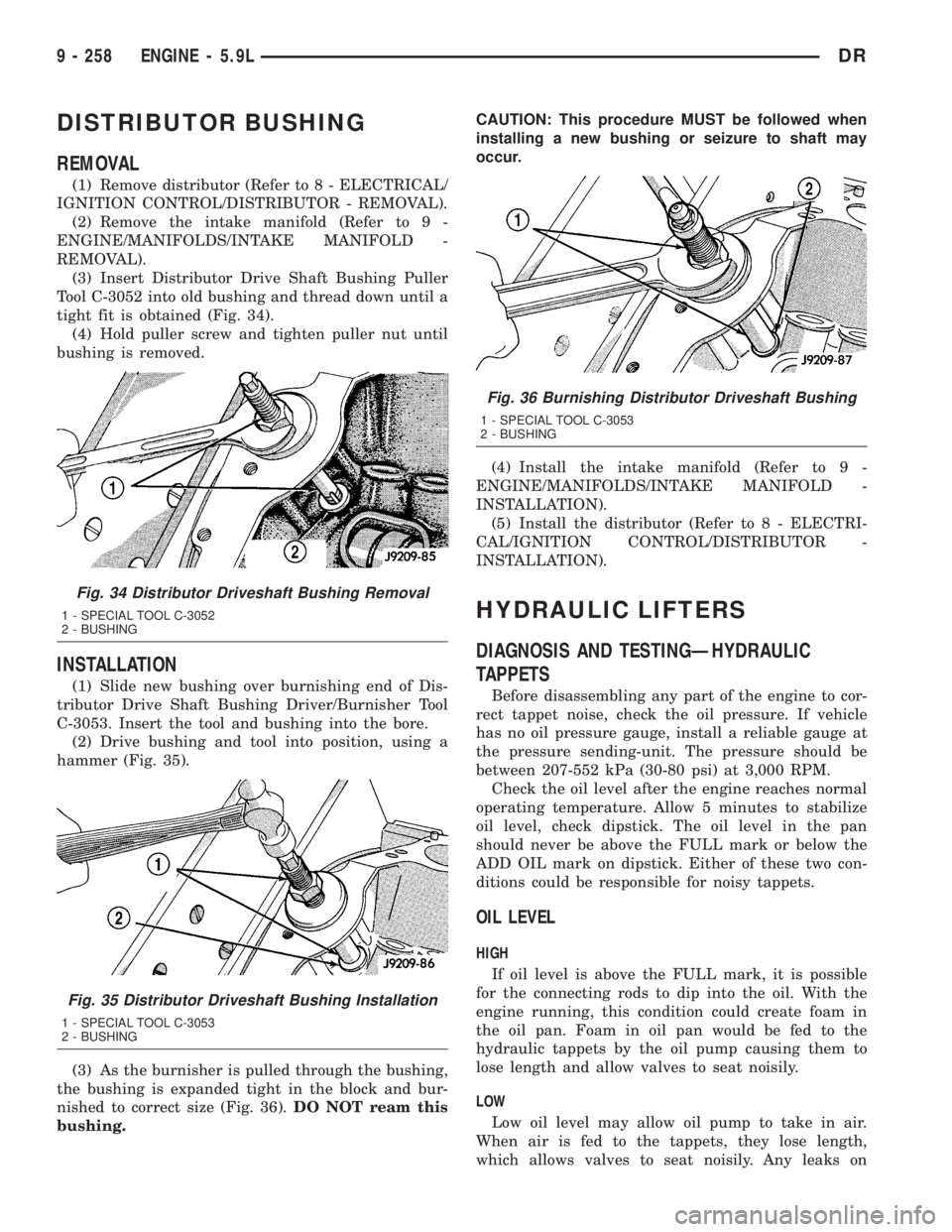
(3) Insert Distributor Drive Shaft Bushing Puller
Tool C-3052 into old bushing and thread down until a
tight fit is obtained (Fig. 34).
(4) Hold puller screw and tighten puller nut until
bushing is removed.
INSTALLATION
(1) Slide new bushing over burnishing end of Dis-
tributor Drive Shaft Bushing Driver/Burnisher Tool
C-3053. Insert the tool and bushing into the bore.
(2) Drive bushing and tool into position, using a
hammer (Fig. 35).
(3) As the burnisher is pulled through the bushing,
the bushing is expanded tight in the block and bur-
nished to correct size (Fig. 36).DO NOT ream this
bushing.CAUTION: This procedure MUST be followed when
installing a new bushing or seizure to shaft may
occur.
(4) Install the intake manifold (Refer to 9 -
ENGINE/MANIFOLDS/INTAKE MANIFOLD -
INSTALLATION).
(5) Install the distributor (Refer to 8 - ELECTRI-
CAL/IGNITION CONTROL/DISTRIBUTOR -
INSTALLATION).
HYDRAULIC LIFTERS
DIAGNOSIS AND TESTINGÐHYDRAULIC
TAPPETS
Before disassembling any part of the engine to cor-
rect tappet noise, check the oil pressure. If vehicle
has no oil pressure gauge, install a reliable gauge at
the pressure sending-unit. The pressure should be
between 207-552 kPa (30-80 psi) at 3,000 RPM.
Check the oil level after the engine reaches normal
operating temperature. Allow 5 minutes to stabilize
oil level, check dipstick. The oil level in the pan
should never be above the FULL mark or below the
ADD OIL mark on dipstick. Either of these two con-
ditions could be responsible for noisy tappets.
OIL LEVEL
HIGH
If oil level is above the FULL mark, it is possible
for the connecting rods to dip into the oil. With the
engine running, this condition could create foam in
the oil pan. Foam in oil pan would be fed to the
hydraulic tappets by the oil pump causing them to
lose length and allow valves to seat noisily.
LOW
Low oil level may allow oil pump to take in air.
When air is fed to the tappets, they lose length,
which allows valves to seat noisily. Any leaks on
Fig. 34 Distributor Driveshaft Bushing Removal
1 - SPECIAL TOOL C-3052
2 - BUSHING
Fig. 35 Distributor Driveshaft Bushing Installation
1 - SPECIAL TOOL C-3053
2 - BUSHING
Fig. 36 Burnishing Distributor Driveshaft Bushing
1 - SPECIAL TOOL C-3053
2 - BUSHING
9 - 258 ENGINE - 5.9LDR
Page 1508 of 2895
intake side of oil pump through which air can be
drawn will create the same tappet action. Check the
lubrication system from the intake strainer to the
pump cover, including the relief valve retainer cap.
When tappet noise is due to aeration, it may be
intermittent or constant, and usually more than one
tappet will be noisy. When oil level and leaks have
been corrected, operate the engine at fast idle. Run
engine for a sufficient time to allow all of the air
inside the tappets to be bled out.
TAPPET NOISE DIAGNOSIS
(1) To determine source of tappet noise, operate
engine at idle with cylinder head covers removed.
(2) Feel each valve spring or rocker arm to detect
noisy tappet. The noisy tappet will cause the affected
spring and/or rocker arm to vibrate or feel rough in
operation.
NOTE: Worn valve guides or cocked springs are
sometimes mistaken for noisy tappets. If such is
the case, noise may be dampened by applying side
thrust on the valve spring. If noise is not apprecia-
bly reduced, it can be assumed the noise is in the
tappet. Inspect the rocker arm push rod sockets
and push rod ends for wear.
(3) Valve tappet noise ranges from light noise to a
heavy click. A light noise is usually caused by exces-
sive leak-down around the unit plunger, or by the
plunger partially sticking in the tappet body cylinder.
The tappet should be replaced. A heavy click is
caused by a tappet check valve not seating, or by for-
eign particles wedged between the plunger and the
tappet body. This will cause the plunger to stick in
the down position. This heavy click will be accompa-
nied by excessive clearance between the valve stem
and rocker arm as valve closes. In either case, tappet
assembly should be removed for inspection and clean-
ing.
(4) The valve train generates a noise very much
like a light tappet noise during normal operation.
Care must be taken to ensure that tappets are mak-
ing the noise. If more than one tappet seems to be
noisy, it's probably not the tappets.
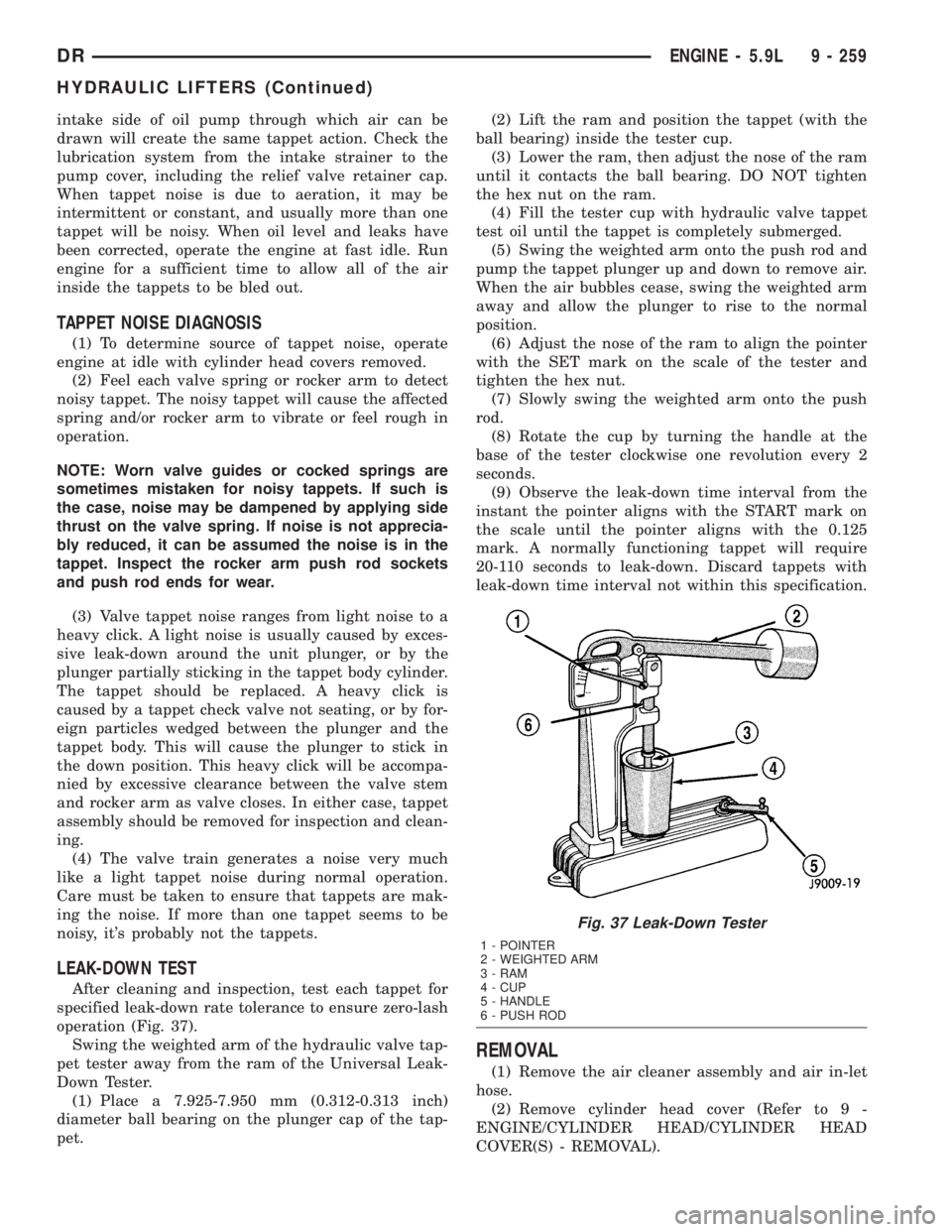
LEAK-DOWN TEST
After cleaning and inspection, test each tappet for
specified leak-down rate tolerance to ensure zero-lash
operation (Fig. 37).
Swing the weighted arm of the hydraulic valve tap-
pet tester away from the ram of the Universal Leak-
Down Tester.
(1) Place a 7.925-7.950 mm (0.312-0.313 inch)
diameter ball bearing on the plunger cap of the tap-
pet.(2) Lift the ram and position the tappet (with the
ball bearing) inside the tester cup.
(3) Lower the ram, then adjust the nose of the ram
until it contacts the ball bearing. DO NOT tighten
the hex nut on the ram.
(4) Fill the tester cup with hydraulic valve tappet
test oil until the tappet is completely submerged.
(5) Swing the weighted arm onto the push rod and
pump the tappet plunger up and down to remove air.
When the air bubbles cease, swing the weighted arm
away and allow the plunger to rise to the normal
position.
(6) Adjust the nose of the ram to align the pointer
with the SET mark on the scale of the tester and
tighten the hex nut.
(7) Slowly swing the weighted arm onto the push
rod.
(8) Rotate the cup by turning the handle at the
base of the tester clockwise one revolution every 2
seconds.
(9) Observe the leak-down time interval from the
instant the pointer aligns with the START mark on
the scale until the pointer aligns with the 0.125
mark. A normally functioning tappet will require
20-110 seconds to leak-down. Discard tappets with
leak-down time interval not within this specification.
REMOVAL
(1) Remove the air cleaner assembly and air in-let
hose.
(2) Remove cylinder head cover (Refer to 9 -
ENGINE/CYLINDER HEAD/CYLINDER HEAD
COVER(S) - REMOVAL).
Fig. 37 Leak-Down Tester
1 - POINTER
2 - WEIGHTED ARM
3 - RAM
4 - CUP
5 - HANDLE
6 - PUSH ROD
DRENGINE - 5.9L 9 - 259
HYDRAULIC LIFTERS (Continued)
Page 1509 of 2895
(3) Remove rocker assembly and push rods (Refer
to 9 - ENGINE/CYLINDER HEAD/ROCKER ARM /
ADJUSTER ASSY - REMOVAL). Identify push rods
to ensure installation in original locations.
(4) Remove intake manifold (Refer to 9 - ENGINE/
MANIFOLDS/INTAKE MANIFOLD - REMOVAL).
(5) Remove yoke retainer and aligning yokes.
(6) Slide Hydraulic Tappet Remover/Installer Tool
C-4129-A through opening in cylinder head and seat
tool firmly in the head of tappet.
(7) Pull tappet out of bore with a twisting motion.
If all tappets are to be removed, identify tappets to
ensure installation in original location.
(8) If the tappet or bore in cylinder block is scored,
scuffed, or shows signs of sticking, ream the bore to
next oversize. Replace with oversize tappet.
CLEANING
Clean tappet with a suitable solvent. Rinse in hot
water and blow dry with a clean shop rag or com-
pressed air.
INSTALLATION
(1) Lubricate tappets with MopartEngine Oil
Supplement or equivalent.
(2) Install tappets and push rods in their original
positions. Ensure that the oil feed hole in the side of
the tappet body faces up (away from the crankshaft).
(3) Install aligning yokes with ARROW toward
camshaft.
(4) Install yoke retainer. Tighten the bolts to 23
N´m (200 in. lbs.) torque. Install intake manifold
(Refer to 9 - ENGINE/MANIFOLDS/INTAKE MANI-
FOLD - INSTALLATION).
(5) Install rocker arms (Refer to 9 - ENGINE/CYL-
INDER HEAD/ROCKER ARM / ADJUSTER ASSY -
INSTALLATION).
(6) Install cylinder head cover (Refer to 9 -
ENGINE/CYLINDER HEAD/CYLINDER HEAD
COVER(S) - INSTALLATION).
(7) Install air cleaner assembly and air in-let hose.
(8) Start and operate engine. Warm up to normal
operating temperature.
CAUTION: To prevent damage to valve mechanism,
engine must not be run above fast idle until all
hydraulic tappets have filled with oil and have
become quiet.
PISTON & CONNECTING ROD
DESCRIPTION
The pistons are made of aluminum and have three
ring grooves, the top two grooves are for the compres-
sion rings and the bottom groove is for the oil control
ring. The connecting rods are forged steel and are
coined prior to heat treat. The piston pins are press
fit.
STANDARD PROCEDURE - PISTON FITTING
Piston and cylinder wall must be clean and dry.
Specified clearance between the piston and the cylin-
der wall is 0.013-0.038 mm (0.0005-0.0015 inch) at
21ÉC (70ÉF).
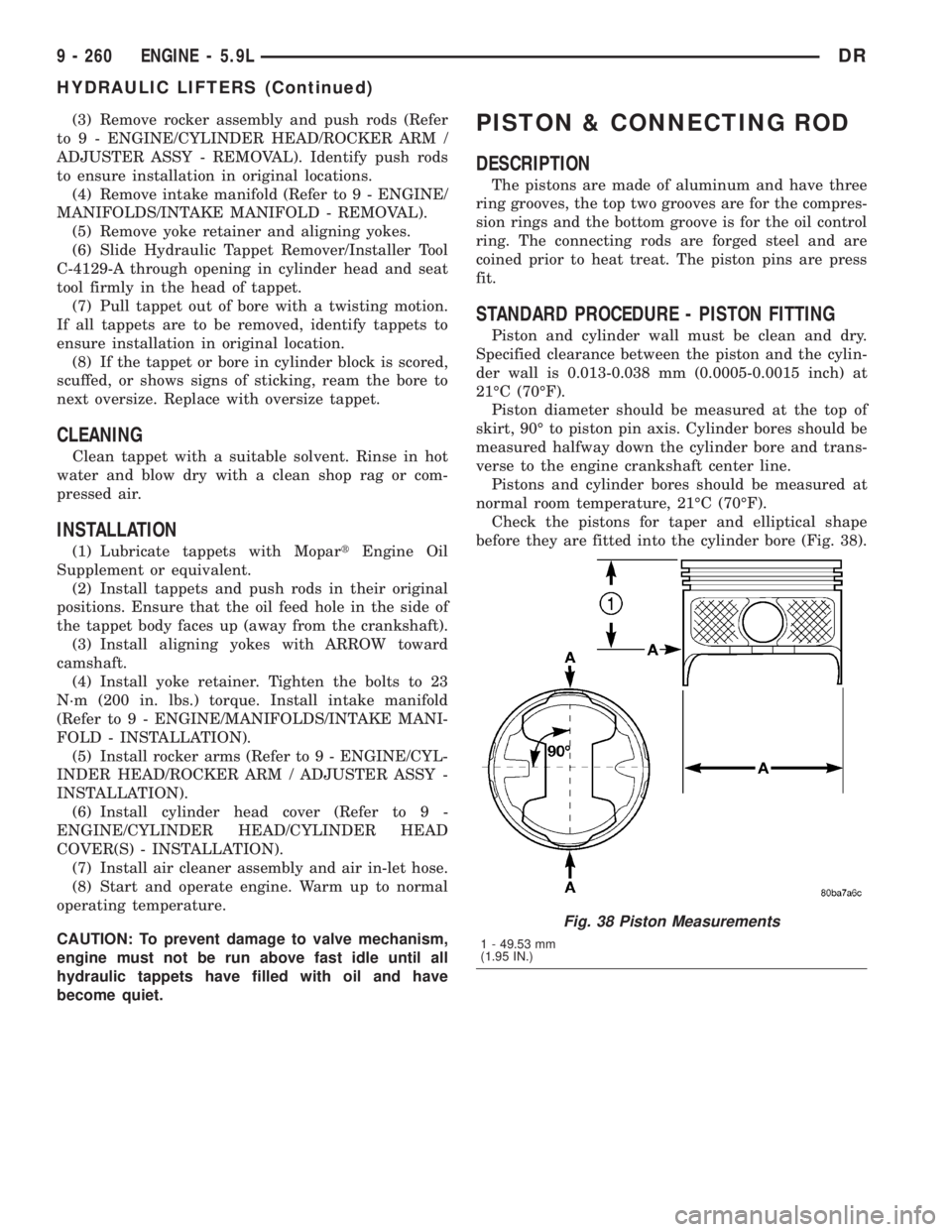
Piston diameter should be measured at the top of
skirt, 90É to piston pin axis. Cylinder bores should be
measured halfway down the cylinder bore and trans-
verse to the engine crankshaft center line.
Pistons and cylinder bores should be measured at
normal room temperature, 21ÉC (70ÉF).
Check the pistons for taper and elliptical shape
before they are fitted into the cylinder bore (Fig. 38).
Fig. 38 Piston Measurements
1 - 49.53 mm
(1.95 IN.)
9 - 260 ENGINE - 5.9LDR
HYDRAULIC LIFTERS (Continued)
Page 1510 of 2895
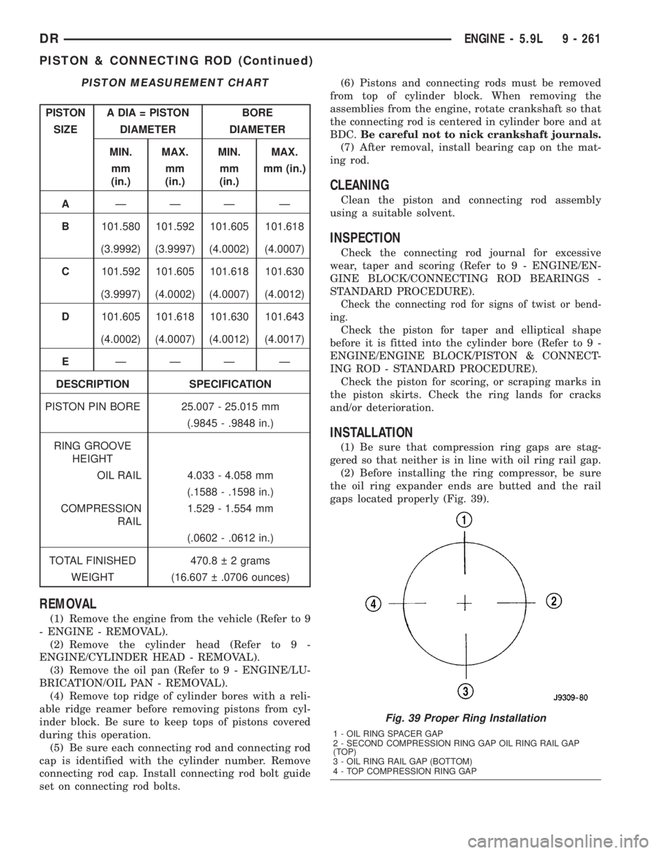
PISTON MEASUREMENT CHART
PISTON A DIA = PISTON BORE
SIZE DIAMETER DIAMETER
MIN. MAX. MIN. MAX.
mm
(in.)mm
(in.)mm
(in.)mm (in.)
AÐÐÐ Ð
B101.580 101.592 101.605 101.618
(3.9992) (3.9997) (4.0002) (4.0007)
C101.592 101.605 101.618 101.630
(3.9997) (4.0002) (4.0007) (4.0012)
D101.605 101.618 101.630 101.643
(4.0002) (4.0007) (4.0012) (4.0017)
EÐÐÐ Ð
DESCRIPTION SPECIFICATION
PISTON PIN BORE 25.007 - 25.015 mm
(.9845 - .9848 in.)
RING GROOVE
HEIGHT
OIL RAIL 4.033 - 4.058 mm
(.1588 - .1598 in.)
COMPRESSION
RAIL1.529 - 1.554 mm
(.0602 - .0612 in.)
TOTAL FINISHED 470.8 2 grams
WEIGHT (16.607 .0706 ounces)
REMOVAL
(1) Remove the engine from the vehicle (Refer to 9
- ENGINE - REMOVAL).
(2) Remove the cylinder head (Refer to 9 -
ENGINE/CYLINDER HEAD - REMOVAL).
(3) Remove the oil pan (Refer to 9 - ENGINE/LU-
BRICATION/OIL PAN - REMOVAL).
(4) Remove top ridge of cylinder bores with a reli-
able ridge reamer before removing pistons from cyl-
inder block. Be sure to keep tops of pistons covered
during this operation.
(5) Be sure each connecting rod and connecting rod
cap is identified with the cylinder number. Remove
connecting rod cap. Install connecting rod bolt guide
set on connecting rod bolts.(6) Pistons and connecting rods must be removed
from top of cylinder block. When removing the
assemblies from the engine, rotate crankshaft so that
the connecting rod is centered in cylinder bore and at
BDC.Be careful not to nick crankshaft journals.
(7) After removal, install bearing cap on the mat-
ing rod.
CLEANING
Clean the piston and connecting rod assembly
using a suitable solvent.
INSPECTION
Check the connecting rod journal for excessive
wear, taper and scoring (Refer to 9 - ENGINE/EN-
GINE BLOCK/CONNECTING ROD BEARINGS -
STANDARD PROCEDURE).
Check the connecting rod for signs of twist or bend-
ing.
Check the piston for taper and elliptical shape
before it is fitted into the cylinder bore (Refer to 9 -
ENGINE/ENGINE BLOCK/PISTON & CONNECT-
ING ROD - STANDARD PROCEDURE).
Check the piston for scoring, or scraping marks in
the piston skirts. Check the ring lands for cracks
and/or deterioration.
INSTALLATION
(1) Be sure that compression ring gaps are stag-
gered so that neither is in line with oil ring rail gap.
(2) Before installing the ring compressor, be sure
the oil ring expander ends are butted and the rail
gaps located properly (Fig. 39).
Fig. 39 Proper Ring Installation
1 - OIL RING SPACER GAP
2 - SECOND COMPRESSION RING GAP OIL RING RAIL GAP
(TOP)
3 - OIL RING RAIL GAP (BOTTOM)
4 - TOP COMPRESSION RING GAP
DRENGINE - 5.9L 9 - 261
PISTON & CONNECTING ROD (Continued)