roof rack DODGE RAM 2003 Service Repair Manual
[x] Cancel search | Manufacturer: DODGE, Model Year: 2003, Model line: RAM, Model: DODGE RAM 2003Pages: 2895, PDF Size: 83.15 MB
Page 547 of 2895
INSTALLATION
(1) Press and hold the brake pedal down.
(2) Align the tab on thenewswitch with the notch
in the switch bracket. Insert the switch in the
bracket and turn it clockwise about 30É to lock it in
place.
(3) Connect the harness wires to the switch.
(4) Release the brake pedal.
(5) Move the release lever on the switch parallel
with the connector to engage the switch plunger. The
switch is now adjusted andcan notbe adjusted
again.
CENTER HIGH MOUNTED
STOP LAMP
REMOVAL
(1) Disconnect and isolate the battery negative
cable.
(2) Remove the CHMSL from the roof panel. Refer
to (Refer to 8 - ELECTRICAL/LAMPS/LIGHTING -
EXTERIOR/CENTER HIGH MOUNTED STOP
LAMP UN - REMOVAL).
(3) Turn the bulb socket 1/4 turn counterclockwise.
(4) Separate the socket from the lamp.
(5) Remove the bulb.
INSTALLATION
(1) Position the bulb in the socket and press into
place.
(2) Position the socket in the lamp.
(3) Turn the bulb socket 1/4 turn clockwise.
(4) Install the CHMSL. Refer to (Refer to 8 -
ELECTRICAL/LAMPS/LIGHTING - EXTERIOR/
CENTER HIGH MOUNTED STOP LAMP UN -
INSTALLATION).
(5) Connect the battery negative cable.
CENTER HIGH MOUNTED
STOP LAMP UNIT
REMOVAL
(1) Disconnect and isolate the battery negative
cable.
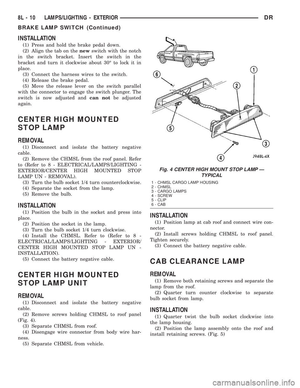
(2) Remove screws holding CHMSL to roof panel
(Fig. 4).
(3) Separate CHMSL from roof.
(4) Disengage wire connector from body wire har-
ness.
(5) Separate CHMSL from vehicle.
INSTALLATION
(1) Position lamp at cab roof and connect wire con-
nector.
(2) Install screws holding CHMSL to roof panel.
Tighten securely.
(3) Connect the battery negative cable.
CAB CLEARANCE LAMP
REMOVAL
(1) Remove both retaining screws and separate the
lamp from the roof.
(2) Quarter turn counter clockwise to separate
bulb socket from lamp.
INSTALLATION
(1) Quarter twist the bulb socket clockwise into
the lamp housing.
(2) Position the lamp assembly onto the roof and
install retaining screws. (Fig. 5)
Fig. 4 CENTER HIGH MOUNT STOP LAMP Ð
TYPICAL
1 - CHMSL CARGO LAMP HOUSING
2 - CHMSL
3 - CARGO LAMPS
4 - SCREW
5 - CLIP
6 - CAB
8L - 10 LAMPS/LIGHTING - EXTERIORDR
BRAKE LAMP SWITCH (Continued)
Page 564 of 2895
MESSAGE SYSTEMS
TABLE OF CONTENTS
page page
OVERHEAD CONSOLE
DESCRIPTION..........................1
OPERATION............................2
DIAGNOSIS AND TESTING - OVERHEAD
CONSOLE............................2
STANDARD PROCEDURE
STANDARD PROCEDURE - READING/
COURTESY LAMP REPLACEMENT.........3
STANDARD PROCEDURE - MODULE LENS
REPLACEMENT.......................3
STANDARD PROCEDURE - MODULE LAMP
REPLACEMENT.......................3
STANDARD PROCEDURE - COMPASS
CALIBRATION.........................3
STANDARD PROCEDURE - COMPASS
DEMAGNETIZING......................4
STANDARD PROCEDURE - COMPASS
VARIATION ADJUSTMENT................4
REMOVAL
OVERHEAD CONSOLE REMOVAL.........5
INSTALLATION..........................5
SPECIAL TOOLS
OVERHEAD CONSOLE..................6
COMPASS/MINI-TRIP COMPUTER
DESCRIPTION..........................6
OPERATION............................7
DIAGNOSIS AND TESTING - COMPASS
MINI-TRIP COMPUTER..................7
REMOVAL.............................7
INSTALLATION..........................7
ELECTRONIC VEHICLE INFO CENTER
DESCRIPTION..........................7OPERATION............................8
DIAGNOSIS AND TESTING - ELECTRONIC
VEHICLE INFORMATION CENTER.........8
STANDARD PROCEDURE - ELECTRONIC
VEHICLE INFORMATION CENTER
PROGRAMMING.......................8
REMOVAL.............................10
INSTALLATION.........................10
AMBIENT TEMP SENSOR
DESCRIPTION.........................10
OPERATION...........................10
DIAGNOSIS AND TESTING
DIAGNOSIS AND TESTING - AMBIENT
TEMPERATURE SENSOR...............11
DIAGNOSIS AND TESTING - AMBIENT
TEMPERATURE SENSOR CIRCUIT........11
REMOVAL.............................11
INSTALLATION.........................11
UNIVERSAL TRANSMITTER
DESCRIPTION.........................11
OPERATION...........................12
DIAGNOSIS AND TESTING - UNIVERSAL
TRANSMITTER.......................12
STANDARD PROCEDURE
STANDARD PROCEDURE - ERASING
TRANSMITTER CODES.................12
STANDARD PROCEDURE - SETTING
TRANSMITTER CODES.................12
REMOVAL.............................13
OVERHEAD CONSOLE
DESCRIPTION
Two different overhead consoles are available on
DR models. The Electronic Vehicle Information Cen-
ter (EVIC) (Fig. 1) or Compass Mini-Trip Computer
(CMTC). All consoles are equipped with two reading/
courtesy lamps. The overhead console is mounted
with screws and two snap clips to a molded plastic
retainer bracket located above the headliner.
COMPASS DISPLAY
All the available overhead consoles on this model
include Compass information. While in the compass/
temperature mode, the compass will display thedirection in which the vehicle is pointed using the
eight major compass headings (Examples: north is N,
northeast is NE). The self-calibrating compass unit
requires no adjusting in normal use. The only cali-
bration that may prove necessary is to drive the vehi-
cle at 5 to 8 kilometers-per-hour (3 to 5 miles-per-
hour), on level ground in a square shaped pattern.
This will reorient the compass unit to its vehicle.
The compass unit also will compensate for magne-
tism the body of the vehicle may acquire during nor-
mal use. However, avoid placing anything magnetic
directly on the roof of the vehicle. Magnetic mounts
for an antenna, a repair order hat, or a funeral pro-
cession flag can exceed the compensating ability of
the compass unit if placed on the roof panel. Mag-
netic bit drivers used on the fasteners that hold the
DRMESSAGE SYSTEMS 8M - 1
Page 652 of 2895
(6) Position the seat belt turning loop onto the
height adjuster on the upper inner B-pillar.
(7) Install and tighten the screw that secures the
seat belt turning loop to the height adjuster. Tighten
the screw to 40 N´m (29 ft. lbs.).
(8) Engage the lower snap features of the new trim
cover over the front outboard seat belt turning loop
and, using hand pressure, press firmly and evenly on
the top of the trim cover until it snaps into place.
SIDE CURTAIN AIRBAG
DESCRIPTION
Optional side curtain airbags are available for this
model when it is also equipped with dual front air-
bags. These airbags are passive, inflatable, Supple-
mental Restraint System (SRS) components, and
vehicles with this equipment can be readily identified
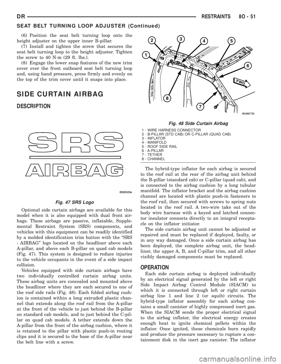
by a molded identification trim button with the ªSRS
- AIRBAGº logo located on the headliner above each
A-pillar, and above each B-pillar on quad cab models
(Fig. 47). This system is designed to reduce injuries
to the vehicle occupants in the event of a side impact
collision.
Vehicles equipped with side curtain airbags have
two individually controlled curtain airbag units.
These airbag units are concealed and mounted above
the headliner where they are each secured to one of
the roof side rails (Fig. 48). Each folded airbag cush-
ion is contained within a long extruded plastic chan-
nel that extends along the roof rail from the A-pillar
at the front of the vehicle to just behind the B-pillar
on standard cab models, and to just behind the C-pil-
lar on quad cab models. A tether extends down the
A-pillar from the front of the airbag cushion, where it
is retained to the pillar with plastic push-in routing
clips and it is secured to the base of the A-pillar near
the belt line with a screw.The hybrid-type inflator for each airbag is secured
to the roof rail at the rear of the airbag unit behind
the B-pillar (standard cab) or C-pillar (quad cab), and
is connected to the airbag cushion by a long tubular
manifold. The inflator bracket and the airbag cushion
channel are located with plastic push-in fasteners to
the roof rail, then secured with screws to spring nuts
located in the roof rail. A two-wire take out of the
body wire harness with a keyed and latched connec-
tor insulator connects directly to an integral recepta-
cle on the inflator initiator.
The side curtain airbag unit cannot be adjusted or
repaired and must be replaced if deployed, faulty, or
in any way damaged. Once a side curtain airbag has
been deployed, the complete airbag unit, the head-
liner, the upper A, B, and C-pillar trim, and all other
visibly damaged components must be replaced.
OPERATION
Each side curtain airbag is deployed individually
by an electrical signal generated by the left or right
Side Impact Airbag Control Module (SIACM) to
which it is connected through left or right curtain
airbag line 1 and line 2 (or squib) circuits. The
hybrid-type inflator assembly for each airbag con-
tains a small canister of highly compressed inert gas.
When the SIACM sends the proper electrical signal
to the airbag inflator, the electrical energy creates
enough heat to ignite chemical pellets within the
inflator. Once ignited, these chemicals burn rapidly
and produce the pressure necessary to rupture a con-
tainment disk in the inert gas canister. The inflator
Fig. 47 SRS Logo
Fig. 48 Side Curtain Airbag
1 - WIRE HARNESS CONNECTOR
2 - B-PILLAR (STD CAB) OR C-PILLAR (QUAD CAB)
3 - INFLATOR
4 - MANIFOLD
5 - ROOF SIDE RAIL
6 - A-PILLAR
7 - TETHER
8 - CHANNEL
DRRESTRAINTS 8O - 51
SEAT BELT TURNING LOOP ADJUSTER (Continued)
Page 653 of 2895
and inert gas canister are sealed and connected to a
tubular manifold so that all of the released gas is
directed into the folded curtain airbag cushion, caus-
ing the cushion to inflate.
As the airbag cushion inflates it will drop down
from the roof rail between the edge of the headliner
and the side glass/body pillars to form a curtain-like
cushion to protect the vehicle occupants during a side
impact collision. The front tether keeps the front por-
tion of the bag taut, thus ensuring that the bag will
deploy in the proper position. Following the airbag
deployment, the airbag cushion quickly deflates by
venting the inert gas through the loose weave of the
cushion fabric, and the deflated cushion hangs down
loosely from the roof rail.
REMOVAL
The following procedure is for replacement of a
faulty or damaged side curtain airbag. If the airbag
is faulty or damaged, but not deployed, review the
recommended procedures for handling non-deployed
supplemental restraints. (Refer to 8 - ELECTRICAL/
RESTRAINTS - STANDARD PROCEDURE - HAN-
DLING NON-DEPLOYED SUPPLEMENTAL
RESTRAINTS). If the side curtain airbag has been
deployed, review the recommended procedures for
service after a supplemental restraint deployment
before removing the airbag from the vehicle. (Refer to
8 - ELECTRICAL/RESTRAINTS - STANDARD PRO-
CEDURE - SERVICE AFTER A SUPPLEMENTAL
RESTRAINT DEPLOYMENT).
WARNING: ON VEHICLES EQUIPPED WITH AIR-
BAGS, DISABLE THE SUPPLEMENTAL RESTRAINT
SYSTEM BEFORE ATTEMPTING ANY STEERING
WHEEL, STEERING COLUMN, DRIVER AIRBAG,
PASSENGER AIRBAG, SEAT BELT TENSIONER,
SIDE CURTAIN AIRBAG, OR INSTRUMENT PANEL
COMPONENT DIAGNOSIS OR SERVICE. DISCON-
NECT AND ISOLATE THE BATTERY NEGATIVE
(GROUND) CABLE, THEN WAIT TWO MINUTES FOR
THE SYSTEM CAPACITOR TO DISCHARGE BEFORE
PERFORMING FURTHER DIAGNOSIS OR SERVICE.
THIS IS THE ONLY SURE WAY TO DISABLE THE
SUPPLEMENTAL RESTRAINT SYSTEM. FAILURE TO
TAKE THE PROPER PRECAUTIONS COULD
RESULT IN ACCIDENTAL AIRBAG DEPLOYMENT
AND POSSIBLE PERSONAL INJURY.
WARNING: WHEN REMOVING A DEPLOYED AIR-
BAG, RUBBER GLOVES, EYE PROTECTION, AND A
LONG-SLEEVED SHIRT SHOULD BE WORN. THERE
MAY BE DEPOSITS ON THE AIRBAG UNIT AND
OTHER INTERIOR SURFACES. IN LARGE DOSES,
THESE DEPOSITS MAY CAUSE IRRITATION TO THE
SKIN AND EYES.WARNING: USE EXTREME CARE TO PREVENT ANY
FOREIGN MATERIAL FROM ENTERING THE SIDE
CURTAIN AIRBAG, OR BECOMING ENTRAPPED
BETWEEN THE SIDE CURTAIN AIRBAG CUSHION
AND THE HEADLINER. FAILURE TO OBSERVE THIS
WARNING COULD RESULT IN OCCUPANT INJURIES
UPON AIRBAG DEPLOYMENT.
(1) Disconnect and isolate the battery negative
cable. Wait two minutes for the system capacitor to
discharge before further service.
(2) Remove the headliner from the vehicle. (Refer
to 23 - BODY/INTERIOR/HEADLINER - REMOV-
AL).
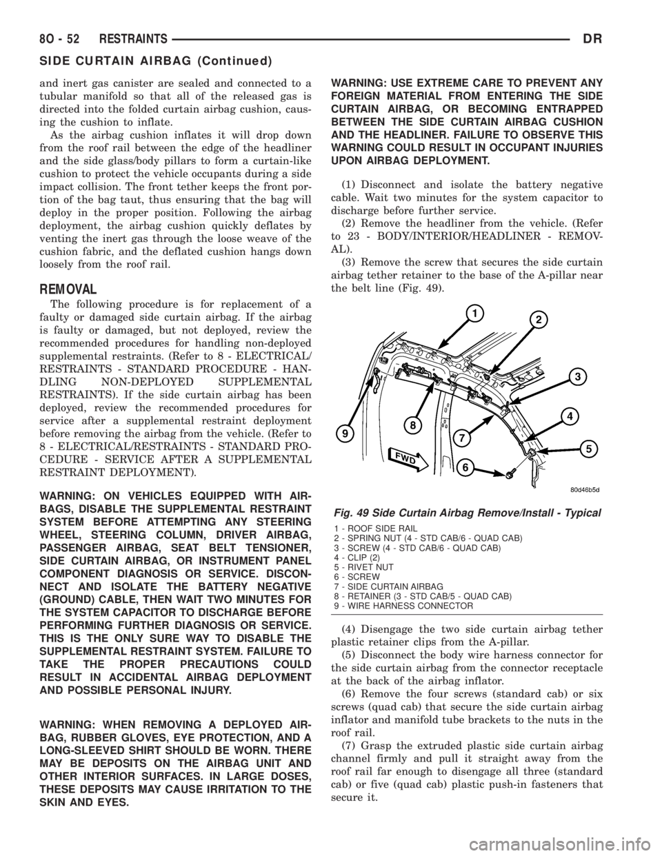
(3) Remove the screw that secures the side curtain
airbag tether retainer to the base of the A-pillar near
the belt line (Fig. 49).
(4) Disengage the two side curtain airbag tether
plastic retainer clips from the A-pillar.
(5) Disconnect the body wire harness connector for
the side curtain airbag from the connector receptacle
at the back of the airbag inflator.
(6) Remove the four screws (standard cab) or six
screws (quad cab) that secure the side curtain airbag
inflator and manifold tube brackets to the nuts in the
roof rail.
(7) Grasp the extruded plastic side curtain airbag
channel firmly and pull it straight away from the
roof rail far enough to disengage all three (standard
cab) or five (quad cab) plastic push-in fasteners that
secure it.
Fig. 49 Side Curtain Airbag Remove/Install - Typical
1 - ROOF SIDE RAIL
2 - SPRING NUT (4 - STD CAB/6 - QUAD CAB)
3 - SCREW (4 - STD CAB/6 - QUAD CAB)
4 - CLIP (2)
5 - RIVET NUT
6 - SCREW
7 - SIDE CURTAIN AIRBAG
8 - RETAINER (3 - STD CAB/5 - QUAD CAB)
9 - WIRE HARNESS CONNECTOR
8O - 52 RESTRAINTSDR
SIDE CURTAIN AIRBAG (Continued)
Page 654 of 2895
(8) Remove the side curtain airbag from the vehi-
cle as a unit.
INSTALLATION
The following procedure is for replacement of a
faulty or damaged side curtain airbag. If the airbag
is faulty or damaged, but not deployed, review the
recommended procedures for handling non-deployed
supplemental restraints. (Refer to 8 - ELECTRICAL/
RESTRAINTS - STANDARD PROCEDURE - HAN-
DLING NON-DEPLOYED SUPPLEMENTAL
RESTRAINTS). If the side curtain airbag has been
deployed, review the recommended procedures for
service after a supplemental restraint deployment
before removing the airbag from the vehicle. (Refer to
8 - ELECTRICAL/RESTRAINTS - STANDARD PRO-
CEDURE - SERVICE AFTER A SUPPLEMENTAL
RESTRAINT DEPLOYMENT).
WARNING: ON VEHICLES EQUIPPED WITH AIR-
BAGS, DISABLE THE SUPPLEMENTAL RESTRAINT
SYSTEM BEFORE ATTEMPTING ANY STEERING
WHEEL, STEERING COLUMN, DRIVER AIRBAG,
PASSENGER AIRBAG, SEAT BELT TENSIONER,
SIDE CURTAIN AIRBAG, OR INSTRUMENT PANEL
COMPONENT DIAGNOSIS OR SERVICE. DISCON-
NECT AND ISOLATE THE BATTERY NEGATIVE
(GROUND) CABLE, THEN WAIT TWO MINUTES FOR
THE SYSTEM CAPACITOR TO DISCHARGE BEFORE
PERFORMING FURTHER DIAGNOSIS OR SERVICE.
THIS IS THE ONLY SURE WAY TO DISABLE THE
SUPPLEMENTAL RESTRAINT SYSTEM. FAILURE TO
TAKE THE PROPER PRECAUTIONS COULD
RESULT IN ACCIDENTAL AIRBAG DEPLOYMENT
AND POSSIBLE PERSONAL INJURY.
WARNING: WHEN REMOVING A DEPLOYED AIR-
BAG, RUBBER GLOVES, EYE PROTECTION, AND A
LONG-SLEEVED SHIRT SHOULD BE WORN. THERE
MAY BE DEPOSITS ON THE AIRBAG UNIT AND
OTHER INTERIOR SURFACES. IN LARGE DOSES,
THESE DEPOSITS MAY CAUSE IRRITATION TO THE
SKIN AND EYES.
WARNING: USE EXTREME CARE TO PREVENT ANY
FOREIGN MATERIAL FROM ENTERING THE SIDE
CURTAIN AIRBAG, OR BECOMING ENTRAPPED
BETWEEN THE SIDE CURTAIN AIRBAG CUSHION
AND THE HEADLINER. FAILURE TO OBSERVE THIS
WARNING COULD RESULT IN OCCUPANT INJURIES
UPON AIRBAG DEPLOYMENT.
(1) Position the side curtain airbag into the vehicle
as a unit.
(2) Align all three (standard cab) or five (quad cab)
plastic push-in fasteners that secure the extrudedplastic side curtain airbag channel with their holes
in the roof side rail and push them straight into the
roof rail until they are fully seated (Fig. 49).
(3) Working from the rear of the vehicle to the
front, install and tighten the four screws (standard
cab) or six screws (quad cab) that secure the side cur-
tain airbag inflator and manifold tube brackets to the
nuts in the roof rail. Tighten the screws to 5 N´m (40
in. lbs.).
(4) Reconnect the body wire harness connector for
the side curtain airbag to the connector receptacle at
the back of the airbag inflator. Be certain the connec-
tor is fully engaged and latched.
(5) Engage the two side curtain airbag tether plas-
tic retainer clips into the A-pillar.
(6) Install and tighten the screw that secures the
side curtain airbag tether retainer to the base of the
A-pillar near the belt line. Tighten the screw to 6
N´m (55 in. lbs.).
(7) Reinstall the headliner into the vehicle. (Refer
to 23 - BODY/INTERIOR/HEADLINER - INSTALLA-
TION).
(8) Do not reconnect the battery negative cable at
this time. The supplemental restraint system verifi-
cation test procedure should be performed following
service of any supplemental restraint system compo-
nent. (Refer to 8 - ELECTRICAL/RESTRAINTS -
STANDARD PROCEDURE - VERIFICATION TEST).
SIDE IMPACT AIRBAG
CONTROL MODULE
DESCRIPTION
On vehicles equipped with the optional side curtain
airbags, a Side Impact Airbag Control Module
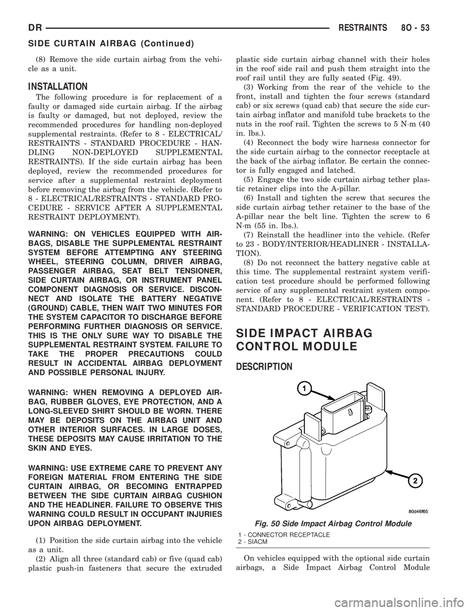
Fig. 50 Side Impact Airbag Control Module
1 - CONNECTOR RECEPTACLE
2 - SIACM
DRRESTRAINTS 8O - 53
SIDE CURTAIN AIRBAG (Continued)
Page 1524 of 2895
WARNING: USE EXTREME CAUTION WHEN THE
ENGINE IS OPERATING. DO NOT STAND IN A
DIRECT LINE WITH THE FAN. DO NOT PUT YOUR
HANDS NEAR THE PULLEYS, BELTS, OR THE FAN.
DO NOT WEAR LOOSE CLOTHING.
(1) Start the engine.
(2) Spray a small stream of water at the suspected
leak area.
(3) If a change in RPMs occur, the area of the sus-
pected leak has been found.
(4) Repair as required.
REMOVAL
(1) Disconnect the negative cable from the battery.
(2) Drain the cooling system (Refer to 7 - COOL-
ING - STANDARD PROCEDURE).
(3) Remove the A/C compressor (Refer to 24 -
HEATING & AIR CONDITIONING/PLUMBING/A/C
COMPRESSOR - REMOVAL).
(4) Remove the generator (Refer to 8 - ELECTRI-
CAL/CHARGING/GENERATOR - REMOVAL).
(5) Remove the accessory drive bracket.
(6) Remove the air cleaner.
(7) Perform the Fuel System Pressure release pro-
cedure (Refer to 14 - FUEL SYSTEM/FUEL DELIV-
ERY - STANDARD PROCEDURE). Disconnect the
fuel lines (Refer to 14 - FUEL SYSTEM/FUEL
DELIVERY/QUICK CONNECT FITTING - STAN-
DARD PROCEDURE).
(8) Disconnect the accelerator linkage (Refer to 14
- FUEL SYSTEM/FUEL INJECTION/THROTTLE
CONTROL CABLE - REMOVAL) and if so equipped,
the speed control and transmission kickdown cables.
(9) Remove the return spring.
(10) Remove the distributor cap and wires.
(11) Disconnect the coil wires.
(12) Disconnect the heat indicator sending unit
wire.
(13) Disconnect the heater hoses and bypass hose.
(14) Remove the closed crankcase ventilation and
evaporation control systems.
(15) Remove intake manifold bolts.
(16) Lift the intake manifold and throttle body out
of the engine compartment as an assembly.
(17) Remove and discard the flange side gaskets
and the front and rear end seals.
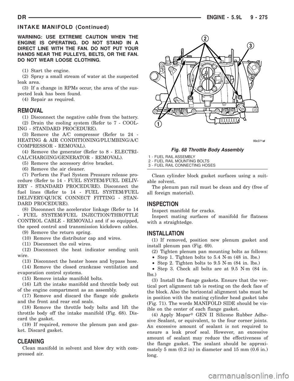
(18) Remove the throttle body bolts and lift the
throttle body off the intake manifold (Fig. 68). Dis-
card the gasket.
(19) If required, remove the plenum pan and gas-
ket. Discard gasket.
CLEANING
Clean manifold in solvent and blow dry with com-
pressed air.Clean cylinder block gasket surfaces using a suit-
able solvent.
The plenum pan rail must be clean and dry (free of
all foreign material).
INSPECTION
Inspect manifold for cracks.
Inspect mating surfaces of manifold for flatness
with a straightedge.
INSTALLATION
(1) If removed, position new plenum gasket and
install plenum pan (Fig. 69).
(2) Tighten plenum pan mounting bolts as follows:
²Step 1. Tighten bolts to 5.4 N´m (48 in. lbs.)
²Step 2. Tighten bolts to 9.5 N´m (84 in. lbs.)
²Step 3. Check all bolts are at 9.5 N´m (84 in.
lbs.)
(3) Install the flange gaskets. Ensure that the ver-
tical port alignment tab is resting on the deck face of
the block. Also the horizontal alignment tabs must be
in position with the mating cylinder head gasket tabs
(Fig. 71). The words MANIFOLD SIDE should be vis-
ible on the center of each flange gasket.
(4) Apply MopartGEN II Silicone Rubber Adhe-
sive Sealant, or equivalent, to the four corner joints.
An excessive amount of sealant is not required to
ensure a leak proof seal. However, an excessive
amount of sealant may reduce the effectiveness of
the flange gasket. The sealant should be approxi-
mately 5 mm (0.2 in) in diameter and 15 mm (0.6 in.)
long.
Fig. 68 Throttle Body Assembly
1 - FUEL RAIL ASSEMBLY
2 - FUEL RAIL MOUNTING BOLTS
3 - FUEL RAIL CONNECTING HOSES
DRENGINE - 5.9L 9 - 275
INTAKE MANIFOLD (Continued)
Page 2664 of 2895
(4) Apply clear glass primer 25 mm (1 in.) wide
around perimeter of windshield and wipe with a new
clean and dry lint- free cloth.
(5) Apply black-out primer onto the glass using the
windshield molding as a guide. The primer should be
15 mm (5/8 in.) wide on the top and sides of the glass
and 25 mm (1 in.) on the bottom of windshield. Allow
at least three minutes drying time.
(6) Locatenewsupport spacers on support brack-
ets and adjust to lowest height. (Fig. 5)
(7) Position seven new foam spacers on the inside
surface of the windshield, flush with the lower and
side edges. (Fig. 7)
(8) Position three new foam spacers on the inside
surface of the windshield, at a minimum distance of
3 mm (0.12 in.) from the top edge of the windshield.
(Fig. 7)
(9) Apply a 13 mm (1/2 in.) high and 10 mm (3/8
in.) wide bead of urethane around the perimeter of
windshield. At the top, apply the bead 7 mm (1/4 in.)
inboard from the glass edge. On the other three sides
apply the bead 14 mm (0.55 in.) inboard from the
glass edge. The urethane bead should be shaped in a
triangular cross-section, this can be achieved by
notching the tip of the applicator (Fig. 8).
(10) Install the a-pillar trim. (Refer to 23 - BODY/
INTERIOR/A-PILLAR TRIM - INSTALLATION)
(11) With the aid of a helper, position the wind-
shield over the windshield opening. Align the refer-
ence marks at the bottom of the windshield to the
support spacers.
(12) Slowly lower windshield glass to the fence
opening guiding the lower corners into proper posi-
tion. Beginning at the bottom and continuing to the
top, push glass onto fence along the A-Pillars. Push
windshield inward to the fence at the bottom corners
(Fig. 9).
(13) Push windshield upward, setting the wind-
shield to roof gap to 1.5 mm (0.06 in.) to 3 mm (0.12
in.) and ratchet up the adjustable support brackets.
(14) Using clean water, lightly mist the support
spacers.
(15) Clean excess urethane from exterior with
MOPARtSuper Clean or equivalent.
(16) Install cowl grill. (Refer to 23 - BODY/EXTE-
RIOR/COWL GRILLE - INSTALLATION).
(17) Install rear view mirror support bracket.
(Refer to 23 - BODY/INTERIOR/REAR VIEW MIR-
ROR - INSTALLATION).(18) Install rear view mirror. (Refer to 23 - BODY/
INTERIOR/REAR VIEW MIRROR - INSTALLA-
TION).
(19) Install the a-pillar weatherstrip retainer.
(Refer to 23 - BODY/WEATHERSTRIP/SEALS/A-
PILLAR WEATHERSTRIP RETAINER - INSTALLA-
TION)
(20) After urethane has cured, remove tape strips
and water test windshield to verify repair.
Fig. 5 CENTER WINDSHIELD AND MARK AT
SUPPORT
1 - WINDSHIELD
2 - INDEX MARKS
3 - SUPPORT SPACERS
Fig. 6 WORK SURFACE SET UP
1 - WINDSHIELD AND MOLDINGS
2 - URETHANE BEAD AROUND GLASS 7mm (0.3 in.) FROM
EDGE
3 - BLOCKS
DRSTATIONARY GLASS 23 - 89
WINDSHIELD (Continued)
Page 2699 of 2895
DESCRIPTION FIGURE
REAR ROOF HEADER TO OUTER ROOF PANEL TO INNER BODY SIDE APERTURE
TO OUTER BODY SIDE APERTURE81
OUTER BODY SIDE APERTURE TO CAB BACK PANEL TO FLOOR SILL, INNER BODY
SIDE APERTURE TO FLOOR SILL82
OUTER BODY SIDE APERTURE TO INNER BODY SIDE APERTURE TO FLOOR SILL 83
REAR FLOOR CROSSMEMBER AND CAB BACK REINFORCEMENT TO CAB BACK
PANEL TO INNER BODY SIDE APERTURE84
CAB BACK REINFORCEMENT TO CAB BACK PANEL 85
CENTER SHOULDER BELT REINFORCEMENT AND TAPPING PLATES TO CAB BACK
REINFORCEMENT86
A-PILLAR REINFORCEMENT TO COWL SIDE PANEL TO OUTER BODY SIDE
APERTURE/APERTURE EXTENSION TO COWL SIDE PANEL87
B-PILLAR REINFORCEMENT TO OUTER ROOF PANEL TO OUTER BODY SIDE
APERTURE88
FRONT ROOF HEADER TO OUTER ROOF PANEL/ROOF BOW TO INNER BODY SIDE
APERTURE/FRONT ROOF HEADER TO A-PILLAR REINFORCEMENT89
INNER BODY SIDE APERTURE TO REAR ROOF HEADER AND OUTER BODY SIDE
APERTURE TO OUTER ROOF PANEL90
FRONT CROSSMEMBER, WHEELHOUSE CROSSMEMBER AND BRACKET SUPPORT
CROSSMEMBER TO BOX FLOOR PAN91
LONG CROSSMEMBER AND FLOOR BOX CROSS SILL TO BOX FLOOR PAN 92
TAPPING PLATES AND SUPPORT BRACKETS TO REAR CROSS BOX SILL, FRONT
WHEELHOUSE, LONG AND BRACKET SUPPORT CROSSMEMBERS93
STAKE POCKET REINFORCEMENTS AND TIE DOWN REINFORCEMENTS TO INNER
BOX SIDE PANEL94
OUTER BOX SIDE REINFORCEMENT BRACES NUT PLATES TO OUTER BOX SIDE
PANEL MOUNTING95
OUTER WHEELHOUSE TO OUTER BOX SIDE PANEL 96
WELD NUT STRIKER CAGE NUT, OUTER BOX SIDE PANEL AND NUT PLATE TO BOX
SIDE TAILGATE REINFORCEMENT97
FRONT BOX PANEL TO FRONT INNER STAKE POCKET REINFORCEMENT TO FRONT
BOX SIDE PANEL98
FRONT CROSSMEMBER TO FRONT BOX SIDE PANEL AND BOX FLOOR PANEL TO
BOX FRONT PANEL99
BOX FLOOR PANEL AND INNER WHEELHOUSE PANEL TO INNER BOX SIDE PANEL 100
FRONT CROSSMEMBER AND END SUPPORT BRACKET TO LONG CROSSMEMBER
TO INNER BOX SIDE PANEL/STAKE POCKET REINFORCEMENT AND BOX FLOOR
SILL TO OUTER TAILGATE PILLAR TO INNER TAILGATE PILLAR101
STAKE POCKET REINFORCEMENT AND BOX FLOOR SILL CROSSMEMBER TO
INNER TAILGATE PILLAR102
INNER TAILGATE PILLAR PANEL TO INNER BOX SIDE PANEL TO TIE DOWN
MOUNTING REINFORCEMENT103
BOX FLOOR SILL CROSSMEMBER TO INNER BOX SIDE PANEL 104
INNER TAILGATE PILLAR TO TAILGATE BOX SIDE REINFORCEMENT TO OUTER
TAILGATE PILLAR105
BOX SIDE PANEL AND OUTER TAILGATE PILLAR TO OUTER BOX SIDE PANEL 106
FRONT BOX PANEL TO OUTER BOX SIDE PANEL 107
23 - 124 BODY STRUCTUREDR
WELD LOCATIONS (Continued)