door lock DODGE RAM 2003 Service Manual PDF
[x] Cancel search | Manufacturer: DODGE, Model Year: 2003, Model line: RAM, Model: DODGE RAM 2003Pages: 2895, PDF Size: 83.15 MB
Page 2599 of 2895
LATCH STRIKER
REMOVAL
(1) Using a grease pencil or equivalent, mark the
position of the striker.
(2) Remove the bolts and remove the striker.
INSTALLATION
(1) Install the striker and install the bolts.
(2) Tighten the bolts to 28 N´m (21 ft. lbs.).
(3) Adjust the striker if needed. (Refer to 23 -
BODY/DOOR - FRONT/LATCH STRIKER - ADJUST-
MENTS)
ADJUSTMENTS
ADJUSTMENT
(1) Using a grease pencil or equivalent, mark the
position of the striker to aid in adjustment.
(2) Loosen the striker bolts.
(3) Change the striker position to adjust the rear
gap and flush measurement. (Refer to 23 - BODY/
BODY STRUCTURE/GAP AND FLUSH - SPECIFI-
CATIONS)
(4) Tighten the bolts to 28 N´m (21 ft. lbs.).
LOCK CYLINDER
REMOVAL
(1) Remove the exterior handle. (Refer to 23 -
BODY/DOOR - FRONT/EXTERIOR HANDLE -
REMOVAL)
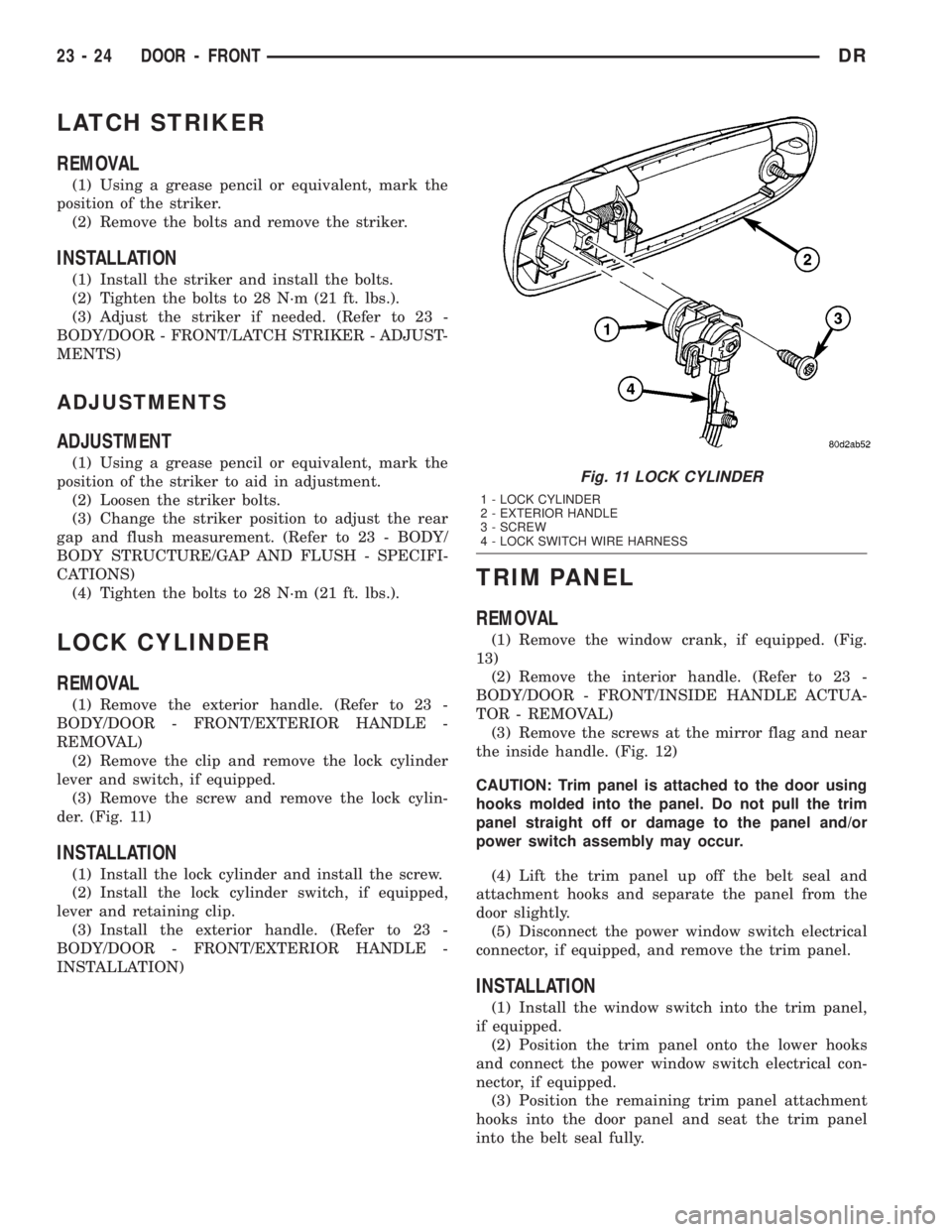
(2) Remove the clip and remove the lock cylinder
lever and switch, if equipped.
(3) Remove the screw and remove the lock cylin-
der. (Fig. 11)
INSTALLATION
(1) Install the lock cylinder and install the screw.
(2) Install the lock cylinder switch, if equipped,
lever and retaining clip.
(3) Install the exterior handle. (Refer to 23 -
BODY/DOOR - FRONT/EXTERIOR HANDLE -
INSTALLATION)
TRIM PANEL
REMOVAL
(1) Remove the window crank, if equipped. (Fig.
13)
(2) Remove the interior handle. (Refer to 23 -
BODY/DOOR - FRONT/INSIDE HANDLE ACTUA-
TOR - REMOVAL)
(3) Remove the screws at the mirror flag and near
the inside handle. (Fig. 12)
CAUTION: Trim panel is attached to the door using
hooks molded into the panel. Do not pull the trim
panel straight off or damage to the panel and/or
power switch assembly may occur.
(4) Lift the trim panel up off the belt seal and
attachment hooks and separate the panel from the
door slightly.
(5) Disconnect the power window switch electrical
connector, if equipped, and remove the trim panel.
INSTALLATION
(1) Install the window switch into the trim panel,
if equipped.
(2) Position the trim panel onto the lower hooks
and connect the power window switch electrical con-
nector, if equipped.
(3) Position the remaining trim panel attachment
hooks into the door panel and seat the trim panel
into the belt seal fully.
Fig. 11 LOCK CYLINDER
1 - LOCK CYLINDER
2 - EXTERIOR HANDLE
3 - SCREW
4 - LOCK SWITCH WIRE HARNESS
23 - 24 DOOR - FRONTDR
Page 2611 of 2895
EXTERIOR
TABLE OF CONTENTS
page page
BODY SIDE MOLDINGS
REMOVAL.............................36
INSTALLATION.........................36
BODY ISOLATORS
REMOVAL.............................36
INSTALLATION.........................37
CARGO BOX
REMOVAL.............................37
INSTALLATION.........................37
CARGO BOX - TIE DOWN
REMOVAL.............................37
INSTALLATION.........................37
COWL GRILLE
REMOVAL.............................38
INSTALLATION.........................38
EXTERIOR NAME PLATES
REMOVAL.............................38
INSTALLATION.........................38
FRONT FENDER
REMOVAL.............................39
INSTALLATION.........................39
FUEL FILL DOOR
REMOVAL.............................39
INSTALLATION.........................39GRILLE
REMOVAL.............................39
INSTALLATION.........................40
GRILLE FRAME
REMOVAL.............................40
INSTALLATION.........................40
FRONT WHEELHOUSE SPLASH SHIELD
REMOVAL.............................40
INSTALLATION.........................41
REAR WHEELHOUSE SPLASH SHIELD
REMOVAL.............................41
INSTALLATION.........................41
SIDE VIEW MIRROR
REMOVAL.............................41
INSTALLATION.........................41
UPPER RADIATOR CROSSMEMBER
REMOVAL.............................42
INSTALLATION.........................42
SIDE VIEW MIRROR GLASS
REMOVAL.............................42
INSTALLATION.........................44
REAR FENDER
REMOVAL.............................44
INSTALLATION.........................44
BODY SIDE MOLDINGS
REMOVAL
NOTE: Body side moldings are attached to the body
panels with adhesive tape.
(1) Apply a length of masking tape on the body
panel, parallel to the top edge of the molding and to
one end to use as a guide for installation, if neces-
sary.
(2) If temperature is below 21ÉC (70ÉF) warm
molding with a heat lamp or gun. Do not exceed 52ÉC
(120ÉF) when heating molding.
(3) Using a trim stick C-4755 or equivalent,
remove and discard the molding from the outside of
the body panel.
INSTALLATION
(1) Thoroughly clean all residue from the body side
molding attachment area of the body panel.(2) Wipe area with a clean lint free cloth moist-
ened with a 50% solution of water and alcohol and
wipe dry immediately with a dry lint free cloth.
(3) Apply new body side molding using the guide
tape on the body panel and apply consistent and uni-
form pressure of approximately 40 p.s.i. over the
entire surface of the molding.
BODY ISOLATORS
REMOVAL
(1) Loosen all cab to frame mounting bolts (six
standard cab, eight quad cab). (Fig. 1)
(2) Remove the mounting bolts and rebound cush-
ions
(3) Using a floor jack and block of wood under the
cab sill, lift the body to gain access to the isolators.
(4) Remove the isolators.
(5) Install new isolators and repeat steps one
through 4, for the opposite side.
23 - 36 EXTERIORDR
Page 2663 of 2895
WINDSHIELD
WARNING
WINDSHIELD SAFETY PRECAUTIONS
WARNING: DO NOT OPERATE THE VEHICLE
WITHIN 24 HOURS OF WINDSHIELD INSTALLATION.
IT TAKES AT LEAST 24 HOURS FOR URETHANE
ADHESIVE TO CURE. IF IT IS NOT CURED, THE
WINDSHIELD MAY NOT PERFORM PROPERLY IN
AN ACCIDENT.
²URETHANE ADHESIVES ARE APPLIED AS A
SYSTEM. USE GLASS CLEANER, GLASS PREP
SOLVENT, GLASS PRIMER, PVC (VINYL) PRIMER
AND PINCH WELD (FENCE) PRIMER PROVIDED BY
THE ADHESIVE MANUFACTURER. IF NOT, STRUC-
TURAL INTEGRITY COULD BE COMPROMISED.
²DAIMLERCHRYSLER DOES NOT RECOMMEND
GLASS ADHESIVE BY BRAND. TECHNICIANS
SHOULD REVIEW PRODUCT LABELS AND TECHNI-
CAL DATA SHEETS, AND USE ONLY ADHESIVES
THAT THEIR MANUFACTURES WARRANT WILL
RESTORE A VEHICLE TO THE REQUIREMENTS OF
FMVSS 212. TECHNICIANS SHOULD ALSO INSURE
THAT PRIMERS AND CLEANERS ARE COMPATIBLE
WITH THE PARTICULAR ADHESIVE USED.
²BE SURE TO REFER TO THE URETHANE MAN-
UFACTURER'S DIRECTIONS FOR CURING TIME
SPECIFICATIONS, AND DO NOT USE ADHESIVE
AFTER ITS EXPIRATION DATE.
²VAPORS THAT ARE EMITTED FROM THE URE-
THANE ADHESIVE OR PRIMER COULD CAUSE
PERSONAL INJURY. USE THEM IN A WELL-VENTI-
LATED AREA.
²SKIN CONTACT WITH URETHANE ADHESIVE
SHOULD BE AVOIDED. PERSONAL INJURY MAY
RESULT.
²ALWAYS WEAR EYE AND HAND PROTECTION
WHEN WORKING WITH GLASS.
CAUTION: Protect all painted and trimmed surfaces
from coming in contact with urethane or primers.
Be careful not to damage painted surfaces when
removing moldings or cutting urethane around
windshield.
REMOVAL
(1) Remove inside rear view mirror. (Refer to 23 -
BODY/INTERIOR/REAR VIEW MIRROR - REMOV-
AL).
(2) Remove cowl grill. (Refer to 23 - BODY/EXTE-
RIOR/COWL GRILLE - REMOVAL).
(3) Remove the a-pillar weatherstrip retainer.
(Refer to 23 - BODY/WEATHERSTRIP/SEALS/A-
PILLAR WEATHERSTRIP RETAINER - REMOVAL)
(4) Remove the a-pillar trim panels. (Refer to 23 -
BODY/INTERIOR/A-PILLAR TRIM - REMOVAL)
(5) Remove the headliner and from the inside of
the vehicle, cut the upper urethane bonding from
around windshield upper edge using a suitable sharp
cold knife (C-4849). A pneumatic cutting device can
be used but is not recommended. (Refer to 23 -
BODY/INTERIOR/HEADLINER - REMOVAL)
(6) From the outside of the vehicle, cut urethane
bonding from the remaining sides of the windshield
using a suitable sharp cold knife (C-4849). A pneu-
matic cutting device can be used but is not recom-
mended.
(7) Separate windshield from vehicle.
INSTALLATION
WARNING: Allow the urethane at least 24 hours to
cure before returning the vehicle to use.
CAUTION: Roll down the left and right front door
glass and open the rear glass slider (if available)
before installing windshield to avoid pressurizing
the passenger compartment if a door is slammed
before urethane is cured. Water leaks can result.
The windshield fence should be cleaned of most of
its old urethane bonding material. A small amount of
old urethane, approximately 1-2 mm in height,
should remain on the fence. Do not grind off or com-
pletely remove all old urethane from the fence, the
paint finish and bonding strength will be adversely
affected.
(1) Place replacement windshield into windshield
opening and position glass in the center of the open-
ing against the support spacers. Mark the outside
surface of the glass at the support spacers with a
grease pencil or pieces of masking tape and ink pen
to use as a reference for installation. Remove replace-
ment windshield from windshield opening (Fig. 5).
(2) Position the windshield inside up on a suitable
work surface with two padded, wood 10 cm by 10 cm
by 50 cm (4 in. by 4 in. by 20 in.) blocks, placed par-
allel 75 cm (2.5 ft.) apart (Fig. 6).
(3) Clean inside of windshield with MOPAR Glass
Cleaner and lint-free cloth.
23 - 88 STATIONARY GLASSDR
Page 2778 of 2895
(3) Start the engine and hold the idle at 1,000 rpm
with the compressor clutch engaged.
(4) The engine should be at operating temperature.
The doors and windows must be closed.
(5) Insert a thermometer in the driver side center
A/C (panel) outlet. Operate the engine for five min-
utes.
(6) The compressor clutch may cycle, depending
upon the ambient temperature and humidity.
(7) With the compressor clutch engaged, record the
discharge air temperature and the compressor dis-
charge pressure.(8) Compare the discharge air temperature to the
Performance Temperature and Pressure chart. If the
discharge air temperature is high, (Refer to 24 -
HEATING & AIR CONDITIONING/PLUMBING -
DIAGNOSIS AND TESTING - REFRIGERANT SYS-
TEM LEAKS) and (Refer to 24 - HEATING & AIR
CONDITIONING/PLUMBING - SPECIFICATIONS -
CHARGE CAPACITY).
Performance Temperature and Pressure
Ambient Air
Temperature21É C
(70É F)27É C
(80É F)32É C
(90É F)38É C
(100É F)43É C
(110É F)
Air Temperature at
Center Panel Outlet7É C
(45É F)7É C
(45É F)13É C
(55É F)13É C
(55É F)18É C
(64É F)
Compressor Inlet
Pressure at Service
Port (low Side)138 to 207 kPa
(20 to 30 psi)172 to 241
kPa
(25 to 35 psi)207 to 276
kPa
(30 to 40 psi)241 to 310
kPa
(35 to 45 psi)276 to 345 kPa
(40 to 50 psi)
Condensor Out
Pressuree at Service
Port (High Side)1034 to 1724
kPa
(150 to 250
psi)1379 to 2068
kPa
(200 to 300
psi)1724 to 2413
kPa
(250 to 350
psi)1999 to 2689
kPa
(290 to 390
psi)2413 to 2965
kPa
(350 to 430 psi)
(9) Compare the compressor discharge pressure to
the Performance Temperature and Pressure chart. Ifthe compressor discharge pressure is high, see the
Pressure Diagnosis chart.
Pressure Diagnosis
Condition Possible Causes Correction
Constant compressor
engagement and warm air
from passenger vents.1. Low refrigerant system
charge.1. See Plumbing/Diagnosis and Testing -
Refrigerant System Leaks in this group. Test the
refrigerant system for leaks. Repair, evacuate and
charge the refrigerant system, if required.
Equal pressures, but the
compressor clutch does not
engage.1. No refrigerant in the
refrigerant system.1. See Plumbing/Diagnosis and Testing -
Refrigerant System Leaks in this group. Test the
refrigerant system for leaks. Repair, evacuate and
charge the refrigerant system, if required.
2. Faulty fuse. 2. Check the fuses in the Power Distribution
Center and the junction block. Repair the shorted
circuit or component and replace the fuses, if
required.
3. Faulty a/c compressor
clutch coil.3. See A/C Compressor/Diagnosis and Testing -
Compressor Clutch Coil in this group. Test the
compressor clutch coil and replace, if required.
DRHEATING & AIR CONDITIONING 24 - 3
HEATING & AIR CONDITIONING (Continued)
Page 2782 of 2895
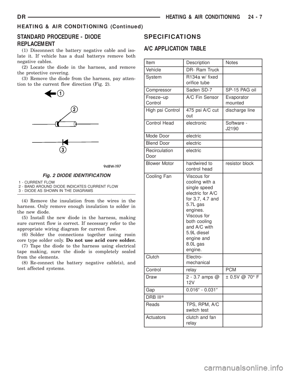
STANDARD PROCEDURE - DIODE
REPLACEMENT
(1) Disconnect the battery negative cable and iso-
late it. If vehicle has a dual batterys remove both
negative cables.
(2) Locate the diode in the harness, and remove
the protective covering.
(3) Remove the diode from the harness, pay atten-
tion to the current flow direction (Fig. 2).
(4) Remove the insulation from the wires in the
harness. Only remove enough insulation to solder in
the new diode.
(5) Install the new diode in the harness, making
sure current flow is correct. If necessary refer to the
appropriate wiring diagram for current flow.
(6) Solder the connections together using rosin
core type solder only.Do not use acid core solder.
(7) Tape the diode to the harness using electrical
tape making, sure the diode is completely sealed
from the elements.
(8) Re-connect the battery negative cable(s), and
test affected systems.
SPECIFICATIONS
A/C APPLICATION TABLE
Item Description Notes
Vehicle DR- Ram Truck
System R134a w/ fixed
orifice tube
Compressor Saden SD-7 SP-15 PAG oil
Freeze±up
ControlA/C Fin Sensor Evaporator
mounted
High psi Control 475 psi A/C cut
outdischarge line
Control Head electronic Software -
J2190
Mode Door electric
Blend Door electric
Recirculation
Doorelectric
Blower Motor hardwired to
control headresistor block
Cooling Fan Viscous for
cooling with a
single speed
electric for A/C
for 3.7, 4.7 and
5.7L gas
engines.
Viscous for
both cooling
and A/C with
5.9L diesel
engine and
8.0L gas
engine.
Clutch Electro-
mechanical
Control relay PCM
Draw 2 - 3.7 amps @
12V 0.5V @ 70É F
Gap 0.0169- 0.0319
DRB IIIT
Reads TPS, RPM, A/C
switch test
Actuators clutch and fan
relay
Fig. 2 DIODE IDENTIFICATION
1 - CURRENT FLOW
2 - BAND AROUND DIODE INDICATES CURRENT FLOW
3 - DIODE AS SHOWN IN THE DIAGRAMS
DRHEATING & AIR CONDITIONING 24 - 7
HEATING & AIR CONDITIONING (Continued)
Page 2784 of 2895
CONTROLS
TABLE OF CONTENTS
page page
A/C COMPRESSOR CLUTCH
DESCRIPTION..........................9
OPERATION............................9
DIAGNOSIS AND TESTING - A/C
COMPRESSOR CLUTCH COIL...........10
STANDARD PROCEDURE - A/C
COMPRESSOR CLUTCH BREAK-IN.......10
REMOVAL.............................10
INSPECTION..........................12
INSTALLATION.........................12
A/C COMPRESSOR CLUTCH RELAY
DESCRIPTION.........................13
OPERATION...........................13
DIAGNOSIS AND TESTING - COMPRESSOR
CLUTCH RELAY......................13
REMOVAL.............................14
INSTALLATION.........................14
A/C HEATER CONTROL
DESCRIPTION.........................14
REMOVAL.............................14
INSTALLATION.........................15
A/C PRESSURE TRANSDUCER
DESCRIPTION - A/C PRESSURE
TRANSDUCER.......................15
OPERATION...........................15
DIAGNOSIS AND TESTING - A/C PRESSURE
TRANSDUCER.......................15
REMOVAL.............................16
INSTALLATION.........................16
BLEND DOOR ACTUATOR
DESCRIPTION.........................16
OPERATION...........................16REMOVAL.............................17
INSTALLATION.........................17
BLOWER MOTOR RESISTOR BLOCK
DESCRIPTION.........................17
OPERATION...........................17
DIAGNOSIS AND TESTING - BLOWER
MOTOR RESISTOR....................18
REMOVAL.............................18
INSTALLATION.........................18
BLOWER MOTOR SWITCH
DESCRIPTION.........................18
OPERATION...........................18
DIAGNOSIS AND TESTING - BLOWER
MOTOR SWITCH......................18
REMOVAL.............................19
INSTALLATION.........................19
DEFROST DOOR ACTUATOR
REMOVAL - FLOOR - DEFROST DOOR
ACTUATOR..........................19
INSTALLATION - FLOOR - DEFROST DOOR
ACTUATOR..........................20
MODE DOOR ACTUATOR
DESCRIPTION.........................20
OPERATION...........................21
REMOVAL.............................21
INSTALLATION.........................22
RECIRCULATION DOOR ACTUATOR
DESCRIPTION.........................22
OPERATION...........................22
REMOVAL.............................22
INSTALLATION.........................23
A/C COMPRESSOR CLUTCH
DESCRIPTION
The compressor clutch assembly consists of a sta-
tionary electromagnetic coil, a rotor bearing and
rotor assembly, and a clutch plate (Fig. 1). The elec-
tromagnetic coil unit and the rotor bearing and rotor
assembly are each retained on the nose of the com-
pressor front housing with snap rings. The clutch
plate is keyed to the compressor shaft and secured
with a nut. These components provide the means to
engage and disengage the compressor from the
engine serpentine accessory drive belt.
OPERATION
When the clutch coil is energized, it magnetically
draws the clutch into contact with the rotor and
drives the compressor shaft. When the coil is not
energized, the rotor freewheels on the clutch rotor
bearing, which is part of the rotor. The compressor
clutch and coil are the only serviced parts on the
compressor.
The compressor clutch engagement is controlled by
several components: the A/C Heater mode control
switch, the A/C high pressure transducer, the com-
pressor clutch relay, and the (JTEC). The JTEC may
delay compressor clutch engagement for up to thirty
DRCONTROLS 24 - 9
Page 2792 of 2895
trol module learns the blend air door stop positions
during the calibration procedure and will store a
Diagnostic Trouble Code (DTC) for any problems it
detects in the blend door actuator circuits. The blend
door actuator can be diagnosed using a DRBIIItscan
tool. Refer to the appropriate diagnostic information.
REMOVAL
The single zone heating and air conditioning sys-
tem is equipped with a single blend door actuator.
The dual zone system has two blend door actuators,
one for the driver side blend air door and one for the
passenger side blend air door. The same service pro-
cedures can be used for each of these actuators.
WARNING: ON VEHICLES EQUIPPED WITH AIR-
BAGS, DISABLE THE AIRBAG SYSTEM BEFORE
ATTEMPTING ANY STEERING WHEEL, STEERING
COLUMN, OR INSTRUMENT PANEL COMPONENT
DIAGNOSIS OR SERVICE. DISCONNECT AND ISO-
LATE THE BATTERY NEGATIVE (GROUND) CABLE,
THEN WAIT TWO MINUTES FOR THE AIRBAG SYS-
TEM CAPACITOR TO DISCHARGE BEFORE PER-
FORMING FURTHER DIAGNOSIS OR SERVICE. THIS
IS THE ONLY SURE WAY TO DISABLE THE AIRBAG
SYSTEM. FAILURE TO TAKE THE PROPER PRE-
CAUTIONS COULD RESULT IN ACCIDENTAL AIR-
BAG DEPLOYMENT AND POSSIBLE PERSONAL
INJURY.
(1) Disconnect and isolate the battery negative
cable.
(2) Remove the instrument panel assembly(Refer
to 23 - BODY/INSTRUMENT PANEL/INSTRUMENT
PANEL ASSEMBLY - REMOVAL).
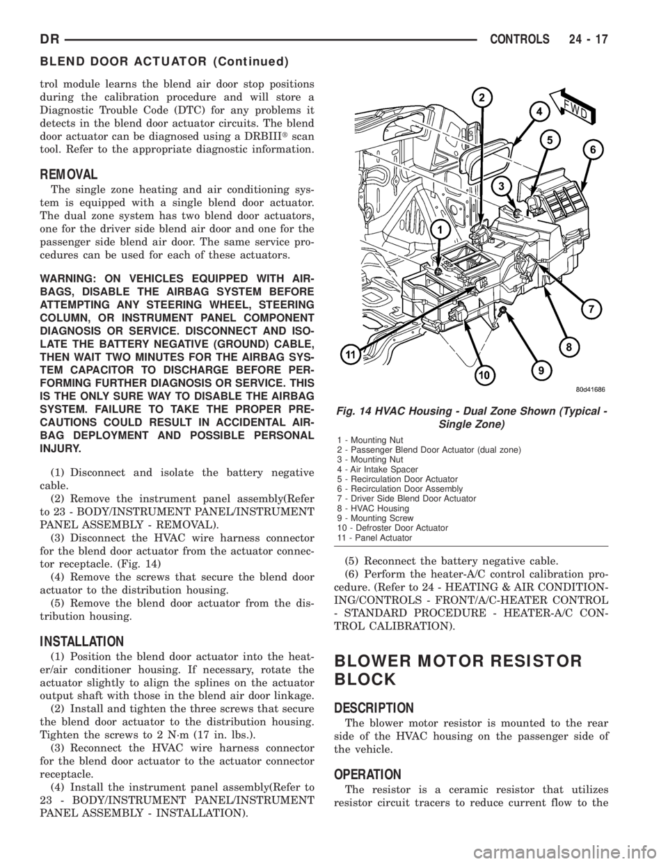
(3) Disconnect the HVAC wire harness connector
for the blend door actuator from the actuator connec-
tor receptacle. (Fig. 14)
(4) Remove the screws that secure the blend door
actuator to the distribution housing.
(5) Remove the blend door actuator from the dis-
tribution housing.
INSTALLATION
(1) Position the blend door actuator into the heat-
er/air conditioner housing. If necessary, rotate the
actuator slightly to align the splines on the actuator
output shaft with those in the blend air door linkage.
(2) Install and tighten the three screws that secure
the blend door actuator to the distribution housing.
Tighten the screws to 2 N´m (17 in. lbs.).
(3) Reconnect the HVAC wire harness connector
for the blend door actuator to the actuator connector
receptacle.
(4) Install the instrument panel assembly(Refer to
23 - BODY/INSTRUMENT PANEL/INSTRUMENT
PANEL ASSEMBLY - INSTALLATION).(5) Reconnect the battery negative cable.
(6) Perform the heater-A/C control calibration pro-
cedure. (Refer to 24 - HEATING & AIR CONDITION-
ING/CONTROLS - FRONT/A/C-HEATER CONTROL
- STANDARD PROCEDURE - HEATER-A/C CON-
TROL CALIBRATION).BLOWER MOTOR RESISTOR
BLOCK
DESCRIPTION
The blower motor resistor is mounted to the rear
side of the HVAC housing on the passenger side of
the vehicle.
OPERATION
The resistor is a ceramic resistor that utilizes
resistor circuit tracers to reduce current flow to the
Fig. 14 HVAC Housing - Dual Zone Shown (Typical -
Single Zone)
1 - Mounting Nut
2 - Passenger Blend Door Actuator (dual zone)
3 - Mounting Nut
4 - Air Intake Spacer
5 - Recirculation Door Actuator
6 - Recirculation Door Assembly
7 - Driver Side Blend Door Actuator
8 - HVAC Housing
9 - Mounting Screw
10 - Defroster Door Actuator
11 - Panel Actuator
DRCONTROLS 24 - 17
BLEND DOOR ACTUATOR (Continued)
Page 2793 of 2895
blower. The blower motor switch directs the ground
path through the correct resistor circuit to obtain the
selected speed.
The blower motor resistor cannot be repaired and,
if faulty or damaged, it must be replaced.
DIAGNOSIS AND TESTING - BLOWER MOTOR
RESISTOR
For circuit descriptions and diagrams, (Refer to
Appropriate Wiring Information).
WARNING: ON VEHICLES EQUIPPED WITH AIR-
BAGS, DISABLE THE AIRBAG SYSTEM BEFORE
ATTEMPTING ANY STEERING WHEEL, STEERING
COLUMN, OR INSTRUMENT PANEL COMPONENT
DIAGNOSIS OR SERVICE. DISCONNECT AND ISO-
LATE THE BATTERY NEGATIVE (GROUND) CABLE,
THEN WAIT TWO MINUTES FOR THE AIRBAG SYS-
TEM CAPACITOR TO DISCHARGE BEFORE PER-
FORMING FURTHER DIAGNOSIS OR SERVICE. THIS
IS THE ONLY SURE WAY TO DISABLE THE AIRBAG
SYSTEM. FAILURE TO TAKE THE PROPER PRE-
CAUTIONS COULD RESULT IN AN ACCIDENTAL
AIRBAG DEPLOYMENT AND POSSIBLE PERSONAL
INJURY.
(1) Disconnect and isolate the battery negative
cable.
(2) Reach under the passenger side bottom of the
HVAC unit and unplug the wire harness connector
from the blower motor resistor.
(3) Check for continuity between each of the
blower motor switch input terminals of the resistor
and the resistor output terminal. In each case there
should be continuity. If OK, repair the wire harness
circuits between the blower motor switch and the
blower motor resistor or blower motor relay as
required. If not OK, replace the faulty blower motor
resistor.
REMOVAL
WARNING: ON VEHICLES EQUIPPED WITH AIR-
BAGS, DISABLE THE AIRBAG SYSTEM BEFORE
ATTEMPTING ANY STEERING WHEEL, STEERING
COLUMN, OR INSTRUMENT PANEL COMPONENT
DIAGNOSIS OR SERVICE. DISCONNECT AND ISO-
LATE THE BATTERY NEGATIVE (GROUND) CABLE,
THEN WAIT TWO MINUTES FOR THE AIRBAG SYS-
TEM CAPACITOR TO DISCHARGE BEFORE PER-
FORMING FURTHER DIAGNOSIS OR SERVICE. THIS
IS THE ONLY SURE WAY TO DISABLE THE AIRBAG
SYSTEM. FAILURE TO TAKE THE PROPER PRE-
CAUTIONS COULD RESULT IN AN ACCIDENTAL
AIRBAG DEPLOYMENT AND POSSIBLE PERSONAL
INJURY.(1) Disconnect and isolate the battery negative
cable.
(2) The blower motor resistor is accessable from
the passenger side of the HVAC unit and is located
on the bottom of the HVAC unit.
(3) Pull out the lock on the blower motor resistor
wire harness connector to unlock the connector latch.
(4) Depress the latch on the blower motor resistor
wire harness connector and unplug the connector
from the resistor.
(5) Remove the two screws that secure the resistor
to the HVAC housing.
(6) Remove the resistor from the HVAC housing.
INSTALLATION
(1) Install the new resistor in the HVAC housing.
(2) Install the two screws that secure the resistor
to the HVAC housing and tighten to 2.2 N´m (20 in.
lbs.).
(3) Plug in the blower motor harness connector.
(4) Push in the lock on the blower motor resistor
harness connector.
(5) Close the glove box door.
(6) Connect the battery negative cable.
BLOWER MOTOR SWITCH
DESCRIPTION
The A/C Heater blower motor is controlled by a
four position rotary-type blower motor switch,
mounted in the A/C Heater control panel. The switch
allows the selection of one of four blower motor
speeds, but can only be turned off by selecting the
Off position on the blower motor switch.
OPERATION
The blower motor switch directs the blower motor
ground path through the mode control switch to the
blower motor resistor, or directly to ground, as
required to achieve the selected blower motor speed.
The blower motor switch cannot be repaired and, if
faulty or damaged, the entire A/C Heater control unit
must be replaced.
DIAGNOSIS AND TESTING - BLOWER MOTOR
SWITCH
For circuit descriptions and diagrams, (Refer to
Appropriate Wiring Information).
24 - 18 CONTROLSDR
BLOWER MOTOR RESISTOR BLOCK (Continued)
Page 2823 of 2895
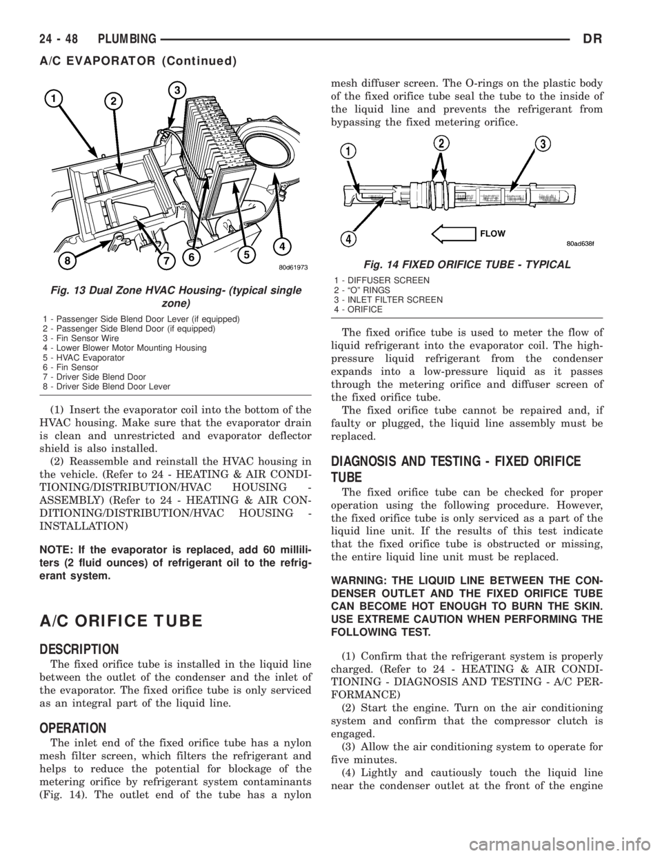
(1) Insert the evaporator coil into the bottom of the
HVAC housing. Make sure that the evaporator drain
is clean and unrestricted and evaporator deflector
shield is also installed.
(2) Reassemble and reinstall the HVAC housing in
the vehicle. (Refer to 24 - HEATING & AIR CONDI-
TIONING/DISTRIBUTION/HVAC HOUSING -
ASSEMBLY) (Refer to 24 - HEATING & AIR CON-
DITIONING/DISTRIBUTION/HVAC HOUSING -
INSTALLATION)
NOTE: If the evaporator is replaced, add 60 millili-
ters (2 fluid ounces) of refrigerant oil to the refrig-
erant system.
A/C ORIFICE TUBE
DESCRIPTION
The fixed orifice tube is installed in the liquid line
between the outlet of the condenser and the inlet of
the evaporator. The fixed orifice tube is only serviced
as an integral part of the liquid line.
OPERATION
The inlet end of the fixed orifice tube has a nylon
mesh filter screen, which filters the refrigerant and
helps to reduce the potential for blockage of the
metering orifice by refrigerant system contaminants
(Fig. 14). The outlet end of the tube has a nylonmesh diffuser screen. The O-rings on the plastic body
of the fixed orifice tube seal the tube to the inside of
the liquid line and prevents the refrigerant from
bypassing the fixed metering orifice.
The fixed orifice tube is used to meter the flow of
liquid refrigerant into the evaporator coil. The high-
pressure liquid refrigerant from the condenser
expands into a low-pressure liquid as it passes
through the metering orifice and diffuser screen of
the fixed orifice tube.
The fixed orifice tube cannot be repaired and, if
faulty or plugged, the liquid line assembly must be
replaced.
DIAGNOSIS AND TESTING - FIXED ORIFICE
TUBE
The fixed orifice tube can be checked for proper
operation using the following procedure. However,
the fixed orifice tube is only serviced as a part of the
liquid line unit. If the results of this test indicate
that the fixed orifice tube is obstructed or missing,
the entire liquid line unit must be replaced.
WARNING: THE LIQUID LINE BETWEEN THE CON-
DENSER OUTLET AND THE FIXED ORIFICE TUBE
CAN BECOME HOT ENOUGH TO BURN THE SKIN.
USE EXTREME CAUTION WHEN PERFORMING THE
FOLLOWING TEST.
(1) Confirm that the refrigerant system is properly
charged. (Refer to 24 - HEATING & AIR CONDI-
TIONING - DIAGNOSIS AND TESTING - A/C PER-
FORMANCE)
(2) Start the engine. Turn on the air conditioning
system and confirm that the compressor clutch is
engaged.
(3) Allow the air conditioning system to operate for
five minutes.
(4) Lightly and cautiously touch the liquid line
near the condenser outlet at the front of the engine
Fig. 13 Dual Zone HVAC Housing- (typical single
zone)
1 - Passenger Side Blend Door Lever (if equipped)
2 - Passenger Side Blend Door (if equipped)
3 - Fin Sensor Wire
4 - Lower Blower Motor Mounting Housing
5 - HVAC Evaporator
6 - Fin Sensor
7 - Driver Side Blend Door
8 - Driver Side Blend Door Lever
Fig. 14 FIXED ORIFICE TUBE - TYPICAL
1 - DIFFUSER SCREEN
2 - ªOº RINGS
3 - INLET FILTER SCREEN
4 - ORIFICE
24 - 48 PLUMBINGDR
A/C EVAPORATOR (Continued)
Page 2857 of 2895

AIRBAG CONTROL MODULE -
INSTALLATION......................8O-12
AIRBAG CONTROL MODULE -
OPERATION.........................8O-10
AIRBAG CONTROL MODULE -
OPERATION, SIDE IMPACT.............8O-54
AIRBAG CONTROL MODULE - REMOVAL . . 8O-11
AIRBAG INDICATOR - DESCRIPTION......8J-18
AIRBAG INDICATOR - OPERATION.......8J-18
AIRBAG ON/OFF SWITCH -
DESCRIPTION, PASSENGER............8O-38
AIRBAG ON/OFF SWITCH -
INSTALLATION, PASSENGER...........8O-39
AIRBAG ON/OFF SWITCH - OPERATION,
PASSENGER........................8O-38
AIRBAG ON/OFF SWITCH - REMOVAL,
PASSENGER........................8O-39
AJAR INDICATOR - DESCRIPTION, DOOR . . 8J-23
AJAR INDICATOR - OPERATION, DOOR . . . 8J-23
AJAR SWITCH - DESCRIPTION, DOOR....8L-25
AJAR SWITCH - OPERATION, DOOR......8L-25
ALIGNMENT - DESCRIPTION, WHEEL.......2-1
ALIGNMENT - OPERATION, WHEEL........2-2
ALIGNMENT - SPECIAL TOOLS,
HEADLAMP..........................8L-7
ALIGNMENT LINK/COIL SUSPENSION -
STANDARD PROCEDURE.................2-5
ALIGNMENT, SPECIAL TOOLS - WHEEL.....2-7
ALIGNMENT, SPECIFICATIONS............2-6
ALUMINUM THREAD REPAIR -
STANDARD PROCEDURE . . 21-156,21-337,21-495
AMBIENT TEMP SENSOR - DESCRIPTION . 8M-10
AMBIENT TEMP SENSOR - OPERATION . . 8M-10
AMBIENT TEMPERATURE SENSOR -
DIAGNOSIS AND TESTING.............8M-11
AMBIENT TEMPERATURE SENSOR
CIRCUIT - DIAGNOSIS AND TESTING....8M-11
AMPLIFIER - DESCRIPTION.............8A-3
AMPLIFIER - INSTALLATION.............8A-4
AMPLIFIER - OPERATION...............8A-3
AMPLIFIER - REMOVAL................8A-3
ANCHOR - DESCRIPTION, CHILD
RESTRAINT.........................8O-14
ANCHOR - INSTALLATION, CHILD
RESTRAINT.........................8O-17
ANCHOR - OPERATION, CHILD
RESTRAINT.........................8O-16
ANCHOR - REMOVAL, CHILD RESTRAINT . 8O-16
ANCHOR & RIGHT OUTBOARD -
INSTALLATION, CENTER...............8O-45
ANCHOR & RIGHT OUTBOARD -
REMOVAL, CENTER...................8O-43
ANTENNA BODY & CABLE -
DESCRIPTION........................8A-4
ANTENNA BODY & CABLE -
INSTALLATION.......................8A-6
ANTENNA BODY & CABLE - OPERATION . . . 8A-4
ANTENNA BODY & CABLE - REMOVAL.....8A-6
ANTENNA BODY AND CABLE -
DIAGNOSIS AND TESTING..............8A-4
ANTENNA CABLE - INSTALLATION,
INSTRUMENT PANEL..................8A-7
ANTENNA CABLE - REMOVAL,
INSTRUMENT PANEL..................8A-6
ANTILOCK - DIAGNOSIS AND TESTING,
REAR WHEEL........................5-42
ANTILOCK BRAKE - DESCRIPTION,
CONTROLLER........................8E-3
ANTILOCK BRAKE - INSTALLATION,
CONTROLLER........................8E-3
ANTILOCK BRAKE - OPERATION,
CONTROLLER........................8E-3
ANTILOCK BRAKE - REMOVAL,
CONTROLLER........................8E-3
A-PILLAR TRIM/GRAB HANDLE -
INSTALLATION.......................23-64
A-PILLAR TRIM/GRAB HANDLE -
REMOVAL..........................23-64
A-PILLAR WEATHERSTRIP RETAINER -
INSTALLATION
.......................23-91
A-PILLAR WEATHERSTRIP RETAINER -
REMOVAL
..........................23-91
APPLICATION TABLE, SPECIFICATIONS -
A/C
................................24-7
AREA LEAKS - DIAGNOSIS AND
TESTING, REAR SEAL
........9-135,9-204,9-64
ARM / ADJUSTER ASSEMBLY -
DESCRIPTION, ROCKER
...............9-124ARM / ADJUSTER ASSEMBLY -
INSTALLATION, ROCKER..........9-124,9-249
ARM / ADJUSTER ASSEMBLY -
REMOVAL, ROCKER.............9-124,9-249
ARM / ADJUSTER ASSY - CLEANING,
ROCKER............................9-310
ARM / ADJUSTER ASSY - DESCRIPTION,
ROCKER............................9-310
ARM / ADJUSTER ASSY - INSPECTION,
ROCKER............................9-311
ARM / ADJUSTER ASSY -
INSTALLATION, ROCKER.....9-198,9-312,9-379
ARM / ADJUSTER ASSY - REMOVAL,
ROCKER.................9-198,9-310,9-379
ARM - DESCRIPTION, ROCKER......9-30,9-36
ARM - DESCRIPTION, WIPER...........8R-18
ARM - INSTALLATION, LOWER
SUSPENSION.........................2-35
ARM - INSTALLATION, PITMAN.........19-36
ARM - INSTALLATION, ROCKER..........9-30
ARM - INSTALLATION, UPPER CONTROL . . . 2-27
ARM - INSTALLATION, WIPER..........8R-19
ARM - OPERATION, WIPER............8R-18
ARM - REMOVAL, LOWER SUSPENSION . . . 2-35
ARM - REMOVAL, PITMAN.............19-35
ARM - REMOVAL, ROCKER..........9-30,9-36
ARM - REMOVAL, UPPER CONTROL......2-27
ARM - REMOVAL, WIPER..............8R-18
ARM BUSHINGS - 2WD (LD) -
INSTALLATION, LOWER CONTROL..........2-14
ARM BUSHINGS - 2WD (LD) -
REMOVAL, LOWER CONTROL............2-12
ARM BUSHINGS - 4WD (LD) -
INSTALLATION, LOWER CONTROL........2-13
ARM BUSHINGS - 4WD (LD) -
REMOVAL, LOWER CONTROL............2-12
ARMREST / SEAT BACK - INSTALLATION,
CENTER............................23-78
ARMREST / SEAT BACK - REMOVAL,
CENTER............................23-77
ASD AND FUEL PUMP RELAYS -
DIAGNOSIS AND TESTING...............8I-7
ASD SENSE - PCM INPUT - OPERATION....8I-6
ASH RECEIVER - INSTALLATION.........23-52
ASH RECEIVER - REMOVAL............23-51
AUDIO - DESCRIPTION.................8A-1
AUDIO - DIAGNOSIS AND TESTING.......8A-2
AUDIO - OPERATION...................8A-1
AUTOMATIC DAY / NIGHT MIRROR -
DESCRIPTION.......................8N-12
AUTOMATIC DAY / NIGHT MIRROR -
DIAGNOSIS AND TESTING.............8N-12
AUTOMATIC DAY / NIGHT MIRROR -
OPERATION.........................8N-12
AUTOMATIC DAY / NIGHT MIRROR -
REMOVAL..........................8N-13
AUTOMATIC LOCKING RETRACTOR -
DESCRIPTION.......................8O-13
AUTOMATIC LOCKING RETRACTOR -
OPERATION.........................8O-14
AUTOMATIC TRANSMISSION -
45RFE/545RFE - DESCRIPTION.........21-489
AUTOMATIC TRANSMISSION -
45RFE/545RFE - OPERATION...........21-490
AUTOMATIC TRANSMISSION - 46RE -
DESCRIPTION......................21-131
AUTOMATIC TRANSMISSION - 46RE -
OPERATION........................21-133
AUTOMATIC TRANSMISSION - 48RE -
DESCRIPTION......................21-312
AUTOMATIC TRANSMISSION - 48RE -
OPERATION........................21-314
AUTOMATIC TRANSMISSION -
DIAGNOSIS AND TESTING......21-139,21-320,
21-491
AUTOMATIC TRANSMISSION FLUID -
DESCRIPTION.........................0-4
AUTOMATIC TRANSMISSION FLUID -
OPERATION...........................0-5
AUXILIARY SPRING BUMPERS (3500) -
INSTALLATION
........................2-40
AUXILIARY SPRING BUMPERS (3500) -
REMOVAL
...........................2-40
AXLE - 10 1/2 AA - ADJUSTMENTS,
REAR
..............................3-104
AXLE - 10 1/2 AA - DESCRIPTION, REAR
. . 3-100
AXLE - 10 1/2 AA - DIAGNOSIS AND
TESTING, REAR
......................3-100AXLE - 10 1/2 AA - INSTALLATION,
REAR..............................3-103
AXLE - 10 1/2 AA - OPERATION, REAR . . . 3-100
AXLE - 10 1/2 AA - REMOVAL, REAR.....3-103
AXLE - 10 1/2 AA - SPECIAL TOOLS,
REAR..............................3-108
AXLE - 10 1/2 AA - SPECIFICATIONS,
REAR..............................3-108
AXLE - 11 1/2 AA - ADJUSTMENTS,
REAR..............................3-131
AXLE - 11 1/2 AA - DESCRIPTION, REAR . . 3-127
AXLE - 11 1/2 AA - DIAGNOSIS AND
TESTING, REAR......................3-127
AXLE - 11 1/2 AA - INSTALLATION,
REAR..............................3-130
AXLE - 11 1/2 AA - OPERATION, REAR . . . 3-127
AXLE - 11 1/2 AA - REMOVAL, REAR.....3-130
AXLE - 11 1/2 AA - SPECIAL TOOLS,
REAR..............................3-135
AXLE - 11 1/2 AA - SPECIFICATIONS,
REAR..............................3-135
AXLE - 9 1/4 - ADJUSTMENTS, REAR.....3-74
AXLE - 9 1/4 - DESCRIPTION, REAR......3-69
AXLE - 9 1/4 - DIAGNOSIS AND
TESTING, REAR.......................3-69
AXLE - 9 1/4 - INSTALLATION, REAR......3-74
AXLE - 9 1/4 - OPERATION, REAR........3-69
AXLE - 9 1/4 - REMOVAL, REAR..........3-74
AXLE - 9 1/4 - SPECIAL TOOLS, REAR.....3-80
AXLE - 9 1/4 - SPECIFICATIONS, REAR......3-79
AXLE - 9 1/4 AA - ADJUSTMENTS,
FRONT..............................3-49
AXLE - 9 1/4 AA - DESCRIPTION, FRONT . . . 3-45
AXLE - 9 1/4 AA - DIAGNOSIS AND
TESTING, FRONT......................3-45
AXLE - 9 1/4 AA - INSTALLATION,
FRONT..............................3-48
AXLE - 9 1/4 AA - OPERATION, FRONT....3-45
AXLE - 9 1/4 AA - REMOVAL, FRONT......3-48
AXLE - 9 1/4 AA - SPECIAL TOOLS,
FRONT..............................3-53
AXLE - 9 1/4 AA - SPECIFICATIONS,
FRONT..............................3-53
AXLE - C205F - ADJUSTMENTS, FRONT....3-21
AXLE - C205F - DESCRIPTION, FRONT.....3-18
AXLE - C205F - DIAGNOSIS AND
TESTING, FRONT......................3-18
AXLE - C205F - INSTALLATION, FRONT....3-21
AXLE - C205F - OPERATION, FRONT......3-18
AXLE - C205F - REMOVAL, FRONT........3-21
AXLE - C205F - SPECIAL TOOLS, FRONT . . . 3-30
AXLE - C205F - SPECIFICATIONS, FRONT . . . 3-29
AXLE - DESCRIPTION...................0-4
AXLE BEARINGS - INSTALLATION . . 3-112,3-139,
3-34,3-84
AXLE BEARINGS - REMOVAL . . 3-112,3-138,3-33,
3-84
AXLE SHAFT SEALS - INSTALLATION . 3-33,3-58,
3-84
AXLE SHAFT SEALS - REMOVAL . 3-33,3-58,3-84
AXLE SHAFTS - ASSEMBLY.............3-58
AXLE SHAFTS - DISASSEMBLY...........3-56
AXLE SHAFTS - INSTALLATION....3-111,3-138,
3-33,3-58,3-83
AXLE SHAFTS - REMOVAL
....3-111,3-138,3-33,
3-56,3-83
BACK - INSTALLATION, CENTER
ARMREST / SEAT
....................23-78
BACK - REAR - INSTALLATION, SEAT
.....23-84
BACK - REAR - REMOVAL, SEAT
........23-84
BACK - REMOVAL, CENTER ARMREST /
SEAT
..............................23-77
BACK CUSHION / COVER - FRONT -
INSTALLATION, SEAT
.................23-83
BACK CUSHION / COVER - FRONT -
REMOVAL, SEAT
.....................23-83
BACK CUSHION / COVER - REAR -
INSTALLATION, SEAT
.................23-85
BACK CUSHION / COVER - REAR -
REMOVAL, SEAT
.....................23-85
BACK HINGE - INSTALLATION, CENTER
SEAT
..............................23-80
BACK HINGE - REMOVAL, CENTER SEAT
. . 23-79
BACK INERTIA HINGE COVER -
INSTALLATION, CENTER SEAT
..........23-78
BACK INERTIA HINGE COVER -
REMOVAL, CENTER SEAT
..............23-78
2 INDEXDR
Description Group-Page Description Group-Page Description Group-Page