brake fluid DODGE RAM 2003 Service Repair Manual
[x] Cancel search | Manufacturer: DODGE, Model Year: 2003, Model line: RAM, Model: DODGE RAM 2003Pages: 2895, PDF Size: 83.15 MB
Page 19 of 2895
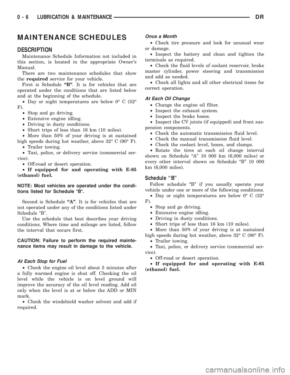
MAINTENANCE SCHEDULES
DESCRIPTION
Maintenance Schedule Information not included in
this section, is located in the appropriate Owner's
Manual.
There are two maintenance schedules that show
therequiredservice for your vehicle.
First is ScheduleªBº. It is for vehicles that are
operated under the conditions that are listed below
and at the beginning of the schedule.
²Day or night temperatures are below 0É C (32É
F).
²Stop and go driving.
²Extensive engine idling.
²Driving in dusty conditions.
²Short trips of less than 16 km (10 miles).
²More than 50% of your driving is at sustained
high speeds during hot weather, above 32É C (90É F).
²Trailer towing.
²Taxi, police, or delivery service (commercial ser-
vice).
²Off-road or desert operation.
²If equipped for and operating with E-85
(ethanol) fuel.
NOTE: Most vehicles are operated under the condi-
tions listed for Schedule(B(.
Second is ScheduleªAº. It is for vehicles that are
not operated under any of the conditions listed under
Schedule9B9.
Use the schedule that best describes your driving
conditions. Where time and mileage are listed, follow
the interval that occurs first.
CAUTION: Failure to perform the required mainte-
nance items may result in damage to the vehicle.
At Each Stop for Fuel
²Check the engine oil level about 5 minutes after
a fully warmed engine is shut off. Checking the oil
level while the vehicle is on level ground will
improve the accuracy of the oil level reading. Add oil
only when the level is at or below the ADD or MIN
mark.
²Check the windshield washer solvent and add if
required.
Once a Month
²Check tire pressure and look for unusual wear
or damage.
²Inspect the battery and clean and tighten the
terminals as required.
²Check the fluid levels of coolant reservoir, brake
master cylinder, power steering and transmission
and add as needed.
²Check all lights and all other electrical items for
correct operation.
At Each Oil Change
²Change the engine oil filter.
²Inspect the exhaust system.
²Inspect the brake hoses.
²Inspect the CV joints (if equipped) and front sus-
pension components.
²Check the automatic transmission fluid level.
²Check the manual transmission fluid level.
²Check the coolant level, hoses, and clamps.
²Rotate the tires at each oil change interval
shown on Schedule ªAº 10 000 km (6,000 miles) or
every other interval shown on Schedule ªBº 10 000
km (6,000 miles).
Schedule ªBº
Follow schedule ªBº if you usually operate your
vehicle under one or more of the following conditions.
²Day or night temperatures are below 0É C (32É
F).
²Stop and go driving.
²Extensive engine idling.
²Driving in dusty conditions.
²Short trips of less than 16 km (10 miles).
²More than 50% of your driving is at sustained
high speeds during hot weather, above 32É C (90É F).
²Trailer towing.
²Taxi, police, or delivery service (commercial ser-
vice).
²Off-road or desert operation.
²If equipped for and operating with E-85
(ethanol) fuel.
0 - 6 LUBRICATION & MAINTENANCEDR
Page 20 of 2895
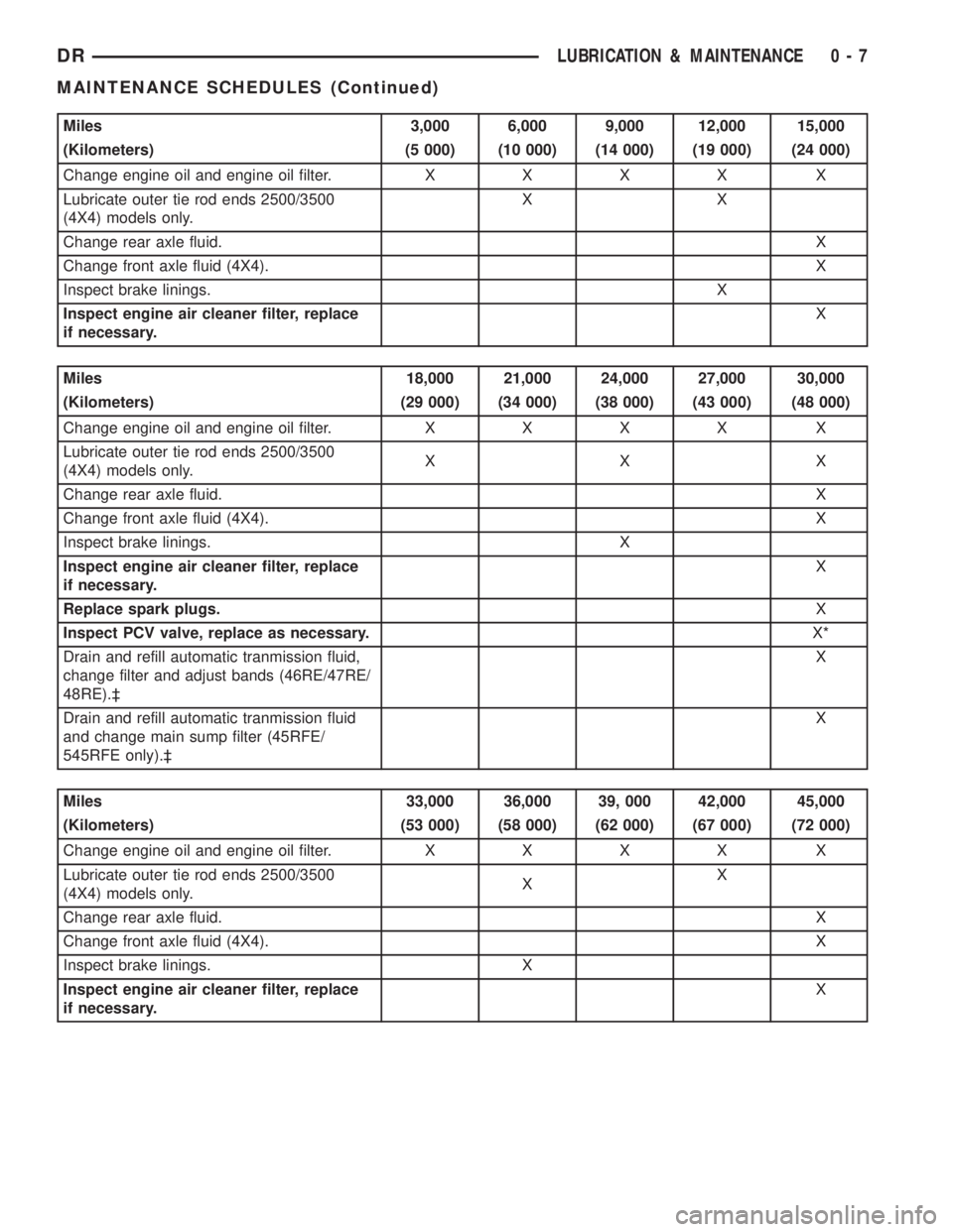
Miles 3,000 6,000 9,000 12,000 15,000
(Kilometers) (5 000) (10 000) (14 000) (19 000) (24 000)
Change engine oil and engine oil filter.XXXX X
Lubricate outer tie rod ends 2500/3500
(4X4) models only.XX
Change rear axle fluid.X
Change front axle fluid (4X4).X
Inspect brake linings.X
Inspect engine air cleaner filter, replace
if necessary.X
Miles 18,000 21,000 24,000 27,000 30,000
(Kilometers) (29 000) (34 000) (38 000) (43 000) (48 000)
Change engine oil and engine oil filter.XXXX X
Lubricate outer tie rod ends 2500/3500
(4X4) models only.XX X
Change rear axle fluid.X
Change front axle fluid (4X4).X
Inspect brake linings. X
Inspect engine air cleaner filter, replace
if necessary.X
Replace spark plugs.X
Inspect PCV valve, replace as necessary.X*
Drain and refill automatic tranmission fluid,
change filter and adjust bands (46RE/47RE/
48RE).³X
Drain and refill automatic tranmission fluid
and change main sump filter (45RFE/
545RFE only).³X
Miles 33,000 36,000 39, 000 42,000 45,000
(Kilometers) (53 000) (58 000) (62 000) (67 000) (72 000)
Change engine oil and engine oil filter.XXXX X
Lubricate outer tie rod ends 2500/3500
(4X4) models only.XX
Change rear axle fluid.X
Change front axle fluid (4X4).X
Inspect brake linings. X
Inspect engine air cleaner filter, replace
if necessary.X
DRLUBRICATION & MAINTENANCE 0 - 7
MAINTENANCE SCHEDULES (Continued)
Page 21 of 2895
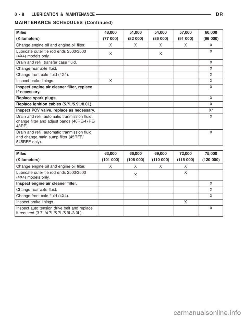
Miles 48,000 51,000 54,000 57,000 60,000
(Kilometers) (77 000) (82 000) (86 000) (91 000) (96 000)
Change engine oil and engine oil filter.XXXX X
Lubricate outer tie rod ends 2500/3500
(4X4) models only.XXX
Drain and refill transfer case fluid.X
Change rear axle fluid.X
Change front axle fluid (4X4).X
Inspect brake linings. X X
Inspect engine air cleaner filter, replace
if necessary.X
Replace spark plugs.X
Replace ignition cables (5.7L/5.9L/8.0L).X
Inspect PCV valve, replace as necessary.X*
Drain and refill automatic tranmission fluid,
change filter and adjust bands (46RE/47RE/
48RE).X
Drain and refill automatic tranmission fluid
and change main sump filter (45RFE/
545RFE only).X
Miles 63,000 66,000 69,000 72,000 75,000
(Kilometers) (101 000) (106 000) (110 000) (115 000) (120 000)
Change engine oil and engine oil filter.XXXX
Lubricate outer tie rod ends 2500/3500
(4X4) models only.XX
Inspect engine air cleaner filter.X
Change rear axle fluid.X
Change front axle fluid (4X4).X
Inspect brake linings.X
Inspect auto tension drive belt and replace
if required (3.7L/4.7L/5.7L/5.9L/8.0L).X
0 - 8 LUBRICATION & MAINTENANCEDR
MAINTENANCE SCHEDULES (Continued)
Page 22 of 2895
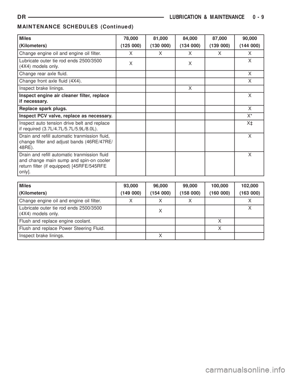
Miles 78,000 81,000 84,000 87,000 90,000
(Kilometers) (125 000) (130 000) (134 000) (139 000) (144 000)
Change engine oil and engine oil filter.XXXX X
Lubricate outer tie rod ends 2500/3500
(4X4) models only.XXX
Change rear axle fluid.X
Change front axle fluid (4X4).X
Inspect brake linings. X
Inspect engine air cleaner filter, replace
if necessary.X
Replace spark plugs.X
Inspect PCV valve, replace as necessary.X*
Inspect auto tension drive belt and replace
if required (3.7L/4.7L/5.7L/5.9L/8.0L).X³
Drain and refill automatic tranmission fluid,
change filter and adjust bands (46RE/47RE/
48RE).X
Drain and refill automatic tranmission fluid
and change main sump and spin-on cooler
return filter (if equipped) [45RFE/545RFE
only].X
Miles 93,000 96,000 99,000 100,000 102,000
(Kilometers) (149 000) (154 000) (158 000) (160 000) (163 000)
Change engine oil and engine oil filter. X X X X
Lubricate outer tie rod ends 2500/3500
(4X4) models only.XX
Flush and replace engine coolant. X
Flush and replace Power Steering Fluid. X
Inspect brake linings. X
DRLUBRICATION & MAINTENANCE 0 - 9
MAINTENANCE SCHEDULES (Continued)
Page 23 of 2895
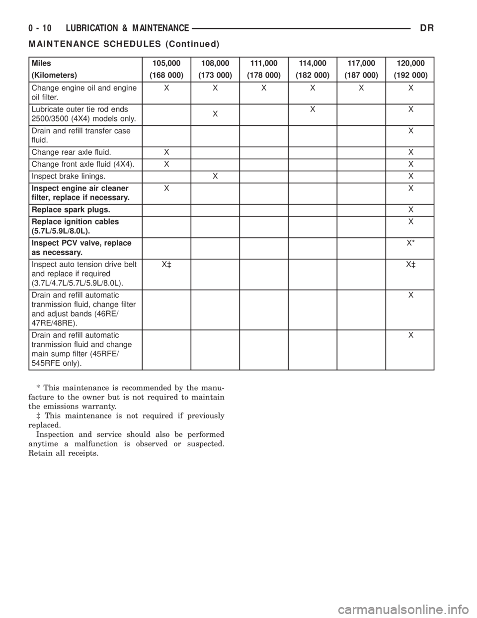
Miles 105,000 108,000 111,000 114,000 117,000 120,000
(Kilometers) (168 000) (173 000) (178 000) (182 000) (187 000) (192 000)
Change engine oil and engine
oil filter.XXXXX X
Lubricate outer tie rod ends
2500/3500 (4X4) models only.XXX
Drain and refill transfer case
fluid.X
Change rear axle fluid. X X
Change front axle fluid (4X4). X X
Inspect brake linings. X X
Inspect engine air cleaner
filter, replace if necessary.XX
Replace spark plugs.X
Replace ignition cables
(5.7L/5.9L/8.0L).X
Inspect PCV valve, replace
as necessary.X*
Inspect auto tension drive belt
and replace if required
(3.7L/4.7L/5.7L/5.9L/8.0L).X³ X³
Drain and refill automatic
tranmission fluid, change filter
and adjust bands (46RE/
47RE/48RE).X
Drain and refill automatic
tranmission fluid and change
main sump filter (45RFE/
545RFE only).X
* This maintenance is recommended by the manu-
facture to the owner but is not required to maintain
the emissions warranty.
³ This maintenance is not required if previously
replaced.
Inspection and service should also be performed
anytime a malfunction is observed or suspected.
Retain all receipts.
0 - 10 LUBRICATION & MAINTENANCEDR
MAINTENANCE SCHEDULES (Continued)
Page 24 of 2895
![DODGE RAM 2003 Service Repair Manual Schedule ªAº
Miles 6,000 12,000 18,000 24,000 30,000
(Kilometers) (10 000) (19 000) (29 000) (38 000) (48 000)
[Months] [6] [12] [18] [24] [30]
Change engine oil and engine oil filter.XXXX X
Check t DODGE RAM 2003 Service Repair Manual Schedule ªAº
Miles 6,000 12,000 18,000 24,000 30,000
(Kilometers) (10 000) (19 000) (29 000) (38 000) (48 000)
[Months] [6] [12] [18] [24] [30]
Change engine oil and engine oil filter.XXXX X
Check t](/img/12/56916/w960_56916-23.png)
Schedule ªAº
Miles 6,000 12,000 18,000 24,000 30,000
(Kilometers) (10 000) (19 000) (29 000) (38 000) (48 000)
[Months] [6] [12] [18] [24] [30]
Change engine oil and engine oil filter.XXXX X
Check transfer case fluid level.X
Lubricate outer tie rod ends 2500/3500
(4X4) models only.XXXX X
Inspect brake linings. X
Replace engine air cleaner filter.X
Replace spark plugs.X
Miles 36,000 42,000 48,000 54,000 60,000 66,000
(Kilometers) (58 000) (67 000) (77 000) (84 000) (96 000) (106 000)
[Months] [36] [42] [48] [54] [60] [66]
Change engine oil and engine
oil filter.XXXXX
X
Check transfer case fluid
level.X
Lubricate outer tie rod ends
2500/3500 (4X4) models only.XXXXX X
Flush and replace engine
coolant at 60 months,
regardless of mileage.X
Inspect brake linings. X X
Replace engine air cleaner
filter.X
Replace spark plugs.X
Inspect PCV valve, replace
as necessary.X*
Replace ignition cables
(5.7L/5.9L/8.0L).X
DRLUBRICATION & MAINTENANCE 0 - 11
MAINTENANCE SCHEDULES (Continued)
Page 25 of 2895
![DODGE RAM 2003 Service Repair Manual Miles 72,000 78,000 84,000 90,000 96,000 100,000
(Kilometers) (115 000) (125 000) (134 000) (144 000) (154 000) (160 000)
[Months] [72] [78] [84] [90] [96]
Change engine oil and engine oil filter.XXXX DODGE RAM 2003 Service Repair Manual Miles 72,000 78,000 84,000 90,000 96,000 100,000
(Kilometers) (115 000) (125 000) (134 000) (144 000) (154 000) (160 000)
[Months] [72] [78] [84] [90] [96]
Change engine oil and engine oil filter.XXXX](/img/12/56916/w960_56916-24.png)
Miles 72,000 78,000 84,000 90,000 96,000 100,000
(Kilometers) (115 000) (125 000) (134 000) (144 000) (154 000) (160 000)
[Months] [72] [78] [84] [90] [96]
Change engine oil and engine oil filter.XXXXX
Lubricate outer tie rod ends 2500/3500
(4X4) models only.XXXXX
Drain and refill transfer case fluid. X
Flush and replace engine coolant, if not
done at 60 mos.X
Flush and replace Power Steering Fluid.X
Inspect brake linings. X X
Replace engine air cleaner filter.X
Replace spark plugs.X
Replace ignition cables (5.7L/5.9L/
8.0L).X
Inspect PCV valve, replace as
necessary.X*
Inspect auto tension drive belt and
replace if required (3.7L/4.7L/5.7L/5.9L/
8.0L).X
Drain and refill automatic tranmission
fluid, change filter and adjust bands
(46RE/47RE/48RE).X
Drain and refill automatic tranmission
fluid and change main sump filter and
spin-on cooler return filter (if equipped)
[45RFE/545RFE only].X
Miles 102,000 108,000 114,000 120,000
(Kilometers) (163 000) (173 000) (182 000) (192 000)
[Months] [102] [108] [114] [120]
Change engine oil and engine oil filter. X X X X
Check transfer case fluid level.X
Lubricate outer tie rod ends 2500/3500 (4X4) models only. X X X X
Inspect brake linings. X
Inspect auto tension drive belt and replace if required
(3.7L/4.7L/5.7L/5.9L/8.0L).X³X³
Replace engine air cleaner filter.X
Replace spark plugs.X
* This maintenance is recommended by the manu-
facture to the owner but is not required to maintain
the emissions warranty.
³ This maintenance is not required if previously
replaced.
Inspection and service should also be performed
anytime a malfunction is observed or suspected.
Retain all receipts.WARNING: You can be badly injured working on or
around a motor vehicle. Do only that service work
for which you have the knowledge and the right
equipment. If you have any doubt about your ability
to perform a service job, take your vehicle to a
competent mechanic.
0 - 12 LUBRICATION & MAINTENANCEDR
MAINTENANCE SCHEDULES (Continued)
Page 26 of 2895
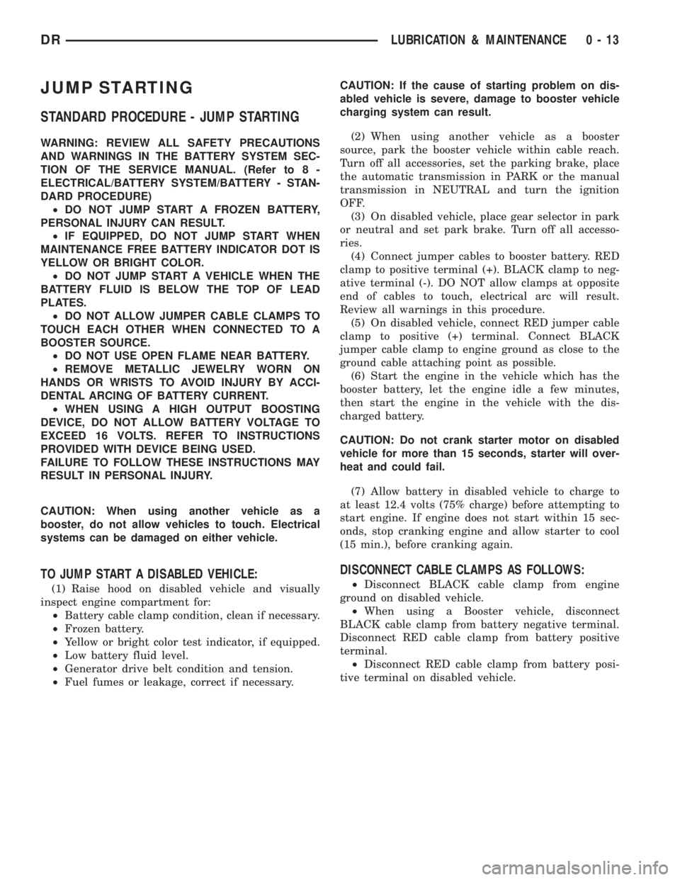
JUMP STARTING
STANDARD PROCEDURE - JUMP STARTING
WARNING: REVIEW ALL SAFETY PRECAUTIONS
AND WARNINGS IN THE BATTERY SYSTEM SEC-
TION OF THE SERVICE MANUAL. (Refer to 8 -
ELECTRICAL/BATTERY SYSTEM/BATTERY - STAN-
DARD PROCEDURE)
²DO NOT JUMP START A FROZEN BATTERY,
PERSONAL INJURY CAN RESULT.
²IF EQUIPPED, DO NOT JUMP START WHEN
MAINTENANCE FREE BATTERY INDICATOR DOT IS
YELLOW OR BRIGHT COLOR.
²DO NOT JUMP START A VEHICLE WHEN THE
BATTERY FLUID IS BELOW THE TOP OF LEAD
PLATES.
²DO NOT ALLOW JUMPER CABLE CLAMPS TO
TOUCH EACH OTHER WHEN CONNECTED TO A
BOOSTER SOURCE.
²DO NOT USE OPEN FLAME NEAR BATTERY.
²REMOVE METALLIC JEWELRY WORN ON
HANDS OR WRISTS TO AVOID INJURY BY ACCI-
DENTAL ARCING OF BATTERY CURRENT.
²WHEN USING A HIGH OUTPUT BOOSTING
DEVICE, DO NOT ALLOW BATTERY VOLTAGE TO
EXCEED 16 VOLTS. REFER TO INSTRUCTIONS
PROVIDED WITH DEVICE BEING USED.
FAILURE TO FOLLOW THESE INSTRUCTIONS MAY
RESULT IN PERSONAL INJURY.
CAUTION: When using another vehicle as a
booster, do not allow vehicles to touch. Electrical
systems can be damaged on either vehicle.
TO JUMP START A DISABLED VEHICLE:
(1) Raise hood on disabled vehicle and visually
inspect engine compartment for:
²Battery cable clamp condition, clean if necessary.
²Frozen battery.
²Yellow or bright color test indicator, if equipped.
²Low battery fluid level.
²Generator drive belt condition and tension.
²Fuel fumes or leakage, correct if necessary.CAUTION: If the cause of starting problem on dis-
abled vehicle is severe, damage to booster vehicle
charging system can result.
(2) When using another vehicle as a booster
source, park the booster vehicle within cable reach.
Turn off all accessories, set the parking brake, place
the automatic transmission in PARK or the manual
transmission in NEUTRAL and turn the ignition
OFF.
(3) On disabled vehicle, place gear selector in park
or neutral and set park brake. Turn off all accesso-
ries.
(4) Connect jumper cables to booster battery. RED
clamp to positive terminal (+). BLACK clamp to neg-
ative terminal (-). DO NOT allow clamps at opposite
end of cables to touch, electrical arc will result.
Review all warnings in this procedure.
(5) On disabled vehicle, connect RED jumper cable
clamp to positive (+) terminal. Connect BLACK
jumper cable clamp to engine ground as close to the
ground cable attaching point as possible.
(6) Start the engine in the vehicle which has the
booster battery, let the engine idle a few minutes,
then start the engine in the vehicle with the dis-
charged battery.
CAUTION: Do not crank starter motor on disabled
vehicle for more than 15 seconds, starter will over-
heat and could fail.
(7) Allow battery in disabled vehicle to charge to
at least 12.4 volts (75% charge) before attempting to
start engine. If engine does not start within 15 sec-
onds, stop cranking engine and allow starter to cool
(15 min.), before cranking again.
DISCONNECT CABLE CLAMPS AS FOLLOWS:
²Disconnect BLACK cable clamp from engine
ground on disabled vehicle.
²When using a Booster vehicle, disconnect
BLACK cable clamp from battery negative terminal.
Disconnect RED cable clamp from battery positive
terminal.
²Disconnect RED cable clamp from battery posi-
tive terminal on disabled vehicle.
DRLUBRICATION & MAINTENANCE 0 - 13
Page 84 of 2895
HALF SHAFT
TABLE OF CONTENTS
page page
HALF SHAFT
CAUTION.............................11
DIAGNOSIS AND TESTING................11
REMOVAL.............................11
INSTALLATION.........................12
SPECIFICATIONS.......................12
SPECIAL TOOLS.......................12CV JOINT-OUTER
REMOVAL.............................13
INSTALLATION.........................13
CV JOINT-INNER
REMOVAL.............................16
INSTALLATION.........................16
HALF SHAFT
CAUTION
CAUTION:: Never grasp half shaft assembly by the
boots. This may cause the boot to pucker or crease
and reduce the service life of the boot.
Avoid over angulating or stroking the C/V joints
when handling the half shaft.
Half shafts exposed to battery acid, transmission
fluid, brake fluid, differential fluid or gasoline may
cause the boots to deteriorate.
DIAGNOSIS AND TESTING
Check for grease at the inboard and outboard C/V
joint. This is a sign of boot or boot clamp damage.
NOISE/VIBRATION IN TURNS
A clicking noise or a vibration in turns could be
caused by a damaged outer C/V or inner tripod joint
seal boot or seal boot clamps. This will result in the
loss/contamination of the joint grease, resulting in
inadequate lubrication of the joint. Noise could also
be caused by another component of the vehicle com-
ing in contact with the half shafts.
CLUNKING NOISE DURING ACCELERATION
This noise may be a result of a damaged or worn
C/V joint. A torn boot or loose/missing clamp on the
inner/outer joint which has allowed the grease to be
lost will damage the C/V joint.
SHUDDER/VIBRATION DURING ACCELERATION
This problem could be a result of a worn/damaged
inner tripod joint or a sticking tripod joint. Improper
wheel alignment may also cause a shudder or vibra-
tion.
VIBRATION AT HIGHWAY SPEEDS
This problem could be a result of out of balance
front tires or tire/wheel runout. Foreign material
(mud, etc.) packed on the backside of the wheel(s)
will also cause a vibration.
REMOVAL
(1) Loosen lug nuts and hub nut while the with
the vehicle brakes applied.
(2) Raise and support the vehicle.
(3) Remove wheel and tire assembly
(4) Remove half shaft hub nut.
(5) Remove brake caliper and rotor.
(6) Position hydraulic jack under lower suspension
arm and raise jack to unload rebound bumper.
(7) Remove lower shock absorber bolt.
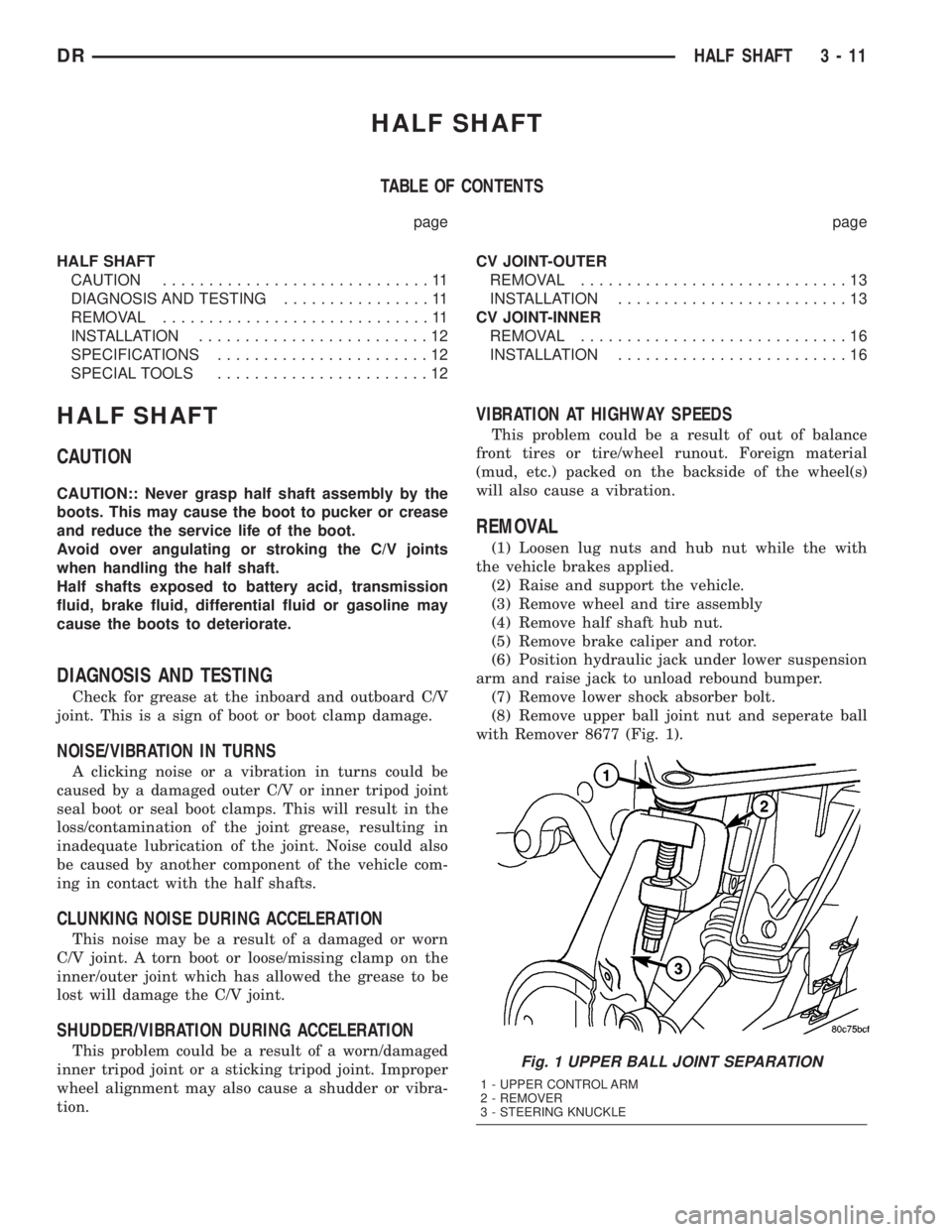
(8) Remove upper ball joint nut and seperate ball
with Remover 8677 (Fig. 1).
Fig. 1 UPPER BALL JOINT SEPARATION
1 - UPPER CONTROL ARM
2 - REMOVER
3 - STEERING KNUCKLE
DRHALF SHAFT 3 - 11
Page 121 of 2895
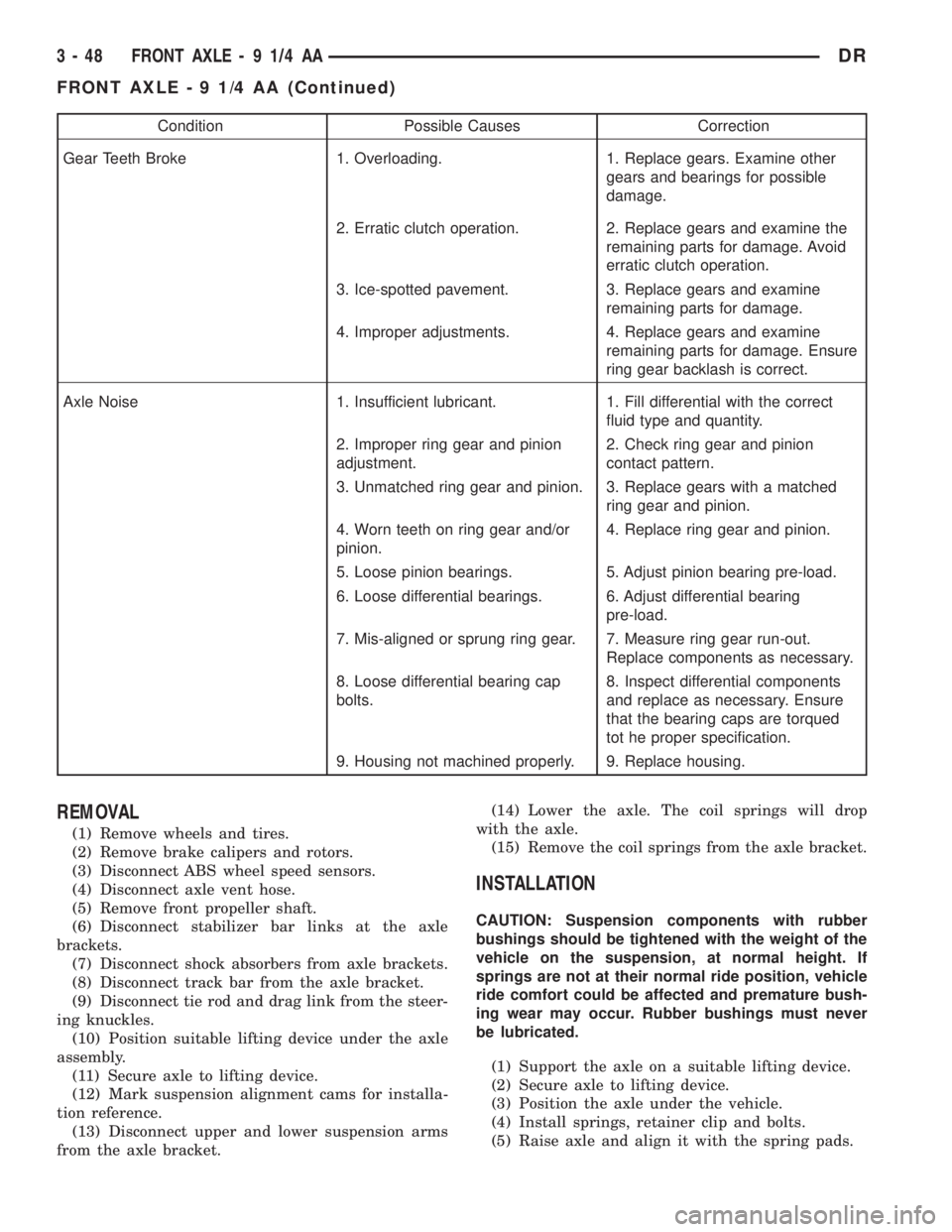
Condition Possible Causes Correction
Gear Teeth Broke 1. Overloading. 1. Replace gears. Examine other
gears and bearings for possible
damage.
2. Erratic clutch operation. 2. Replace gears and examine the
remaining parts for damage. Avoid
erratic clutch operation.
3. Ice-spotted pavement. 3. Replace gears and examine
remaining parts for damage.
4. Improper adjustments. 4. Replace gears and examine
remaining parts for damage. Ensure
ring gear backlash is correct.
Axle Noise 1. Insufficient lubricant. 1. Fill differential with the correct
fluid type and quantity.
2. Improper ring gear and pinion
adjustment.2. Check ring gear and pinion
contact pattern.
3. Unmatched ring gear and pinion. 3. Replace gears with a matched
ring gear and pinion.
4. Worn teeth on ring gear and/or
pinion.4. Replace ring gear and pinion.
5. Loose pinion bearings. 5. Adjust pinion bearing pre-load.
6. Loose differential bearings. 6. Adjust differential bearing
pre-load.
7. Mis-aligned or sprung ring gear. 7. Measure ring gear run-out.
Replace components as necessary.
8. Loose differential bearing cap
bolts.8. Inspect differential components
and replace as necessary. Ensure
that the bearing caps are torqued
tot he proper specification.
9. Housing not machined properly. 9. Replace housing.
REMOVAL
(1) Remove wheels and tires.
(2) Remove brake calipers and rotors.
(3) Disconnect ABS wheel speed sensors.
(4) Disconnect axle vent hose.
(5) Remove front propeller shaft.
(6) Disconnect stabilizer bar links at the axle
brackets.
(7) Disconnect shock absorbers from axle brackets.
(8) Disconnect track bar from the axle bracket.
(9) Disconnect tie rod and drag link from the steer-
ing knuckles.
(10) Position suitable lifting device under the axle
assembly.
(11) Secure axle to lifting device.
(12) Mark suspension alignment cams for installa-
tion reference.
(13) Disconnect upper and lower suspension arms
from the axle bracket.(14) Lower the axle. The coil springs will drop
with the axle.
(15) Remove the coil springs from the axle bracket.
INSTALLATION
CAUTION: Suspension components with rubber
bushings should be tightened with the weight of the
vehicle on the suspension, at normal height. If
springs are not at their normal ride position, vehicle
ride comfort could be affected and premature bush-
ing wear may occur. Rubber bushings must never
be lubricated.
(1) Support the axle on a suitable lifting device.
(2) Secure axle to lifting device.
(3) Position the axle under the vehicle.
(4) Install springs, retainer clip and bolts.
(5) Raise axle and align it with the spring pads.
3 - 48 FRONT AXLE - 9 1/4 AADR
FRONT AXLE - 9 1/4 AA (Continued)