boot DODGE RAM 2003 Service Repair Manual
[x] Cancel search | Manufacturer: DODGE, Model Year: 2003, Model line: RAM, Model: DODGE RAM 2003Pages: 2895, PDF Size: 83.15 MB
Page 48 of 2895
NOTE: Extreme pressure lubrication must be used
on the threaded portions of the tool. This will
increase the longevity of the tool and insure proper
operation during the removal and installation pro-
cess.
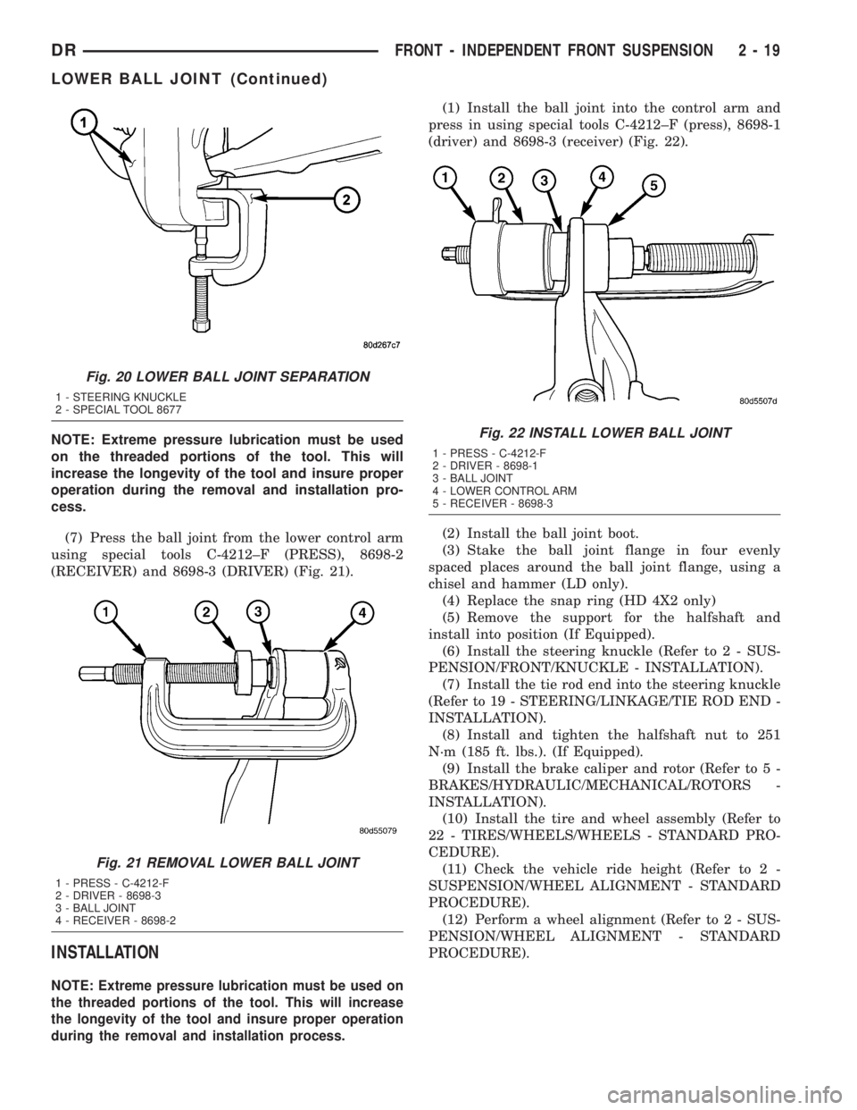
(7) Press the ball joint from the lower control arm
using special tools C-4212±F (PRESS), 8698-2
(RECEIVER) and 8698-3 (DRIVER) (Fig. 21).
INSTALLATION
NOTE: Extreme pressure lubrication must be used on
the threaded portions of the tool. This will increase
the longevity of the tool and insure proper operation
during the removal and installation process.
(1) Install the ball joint into the control arm and
press in using special tools C-4212±F (press), 8698-1
(driver) and 8698-3 (receiver) (Fig. 22).
(2) Install the ball joint boot.
(3) Stake the ball joint flange in four evenly
spaced places around the ball joint flange, using a
chisel and hammer (LD only).
(4) Replace the snap ring (HD 4X2 only)
(5) Remove the support for the halfshaft and
install into position (If Equipped).
(6) Install the steering knuckle (Refer to 2 - SUS-
PENSION/FRONT/KNUCKLE - INSTALLATION).
(7) Install the tie rod end into the steering knuckle
(Refer to 19 - STEERING/LINKAGE/TIE ROD END -
INSTALLATION).
(8) Install and tighten the halfshaft nut to 251
N´m (185 ft. lbs.). (If Equipped).
(9) Install the brake caliper and rotor (Refer to 5 -
BRAKES/HYDRAULIC/MECHANICAL/ROTORS -
INSTALLATION).
(10) Install the tire and wheel assembly (Refer to
22 - TIRES/WHEELS/WHEELS - STANDARD PRO-
CEDURE).
(11) Check the vehicle ride height (Refer to 2 -
SUSPENSION/WHEEL ALIGNMENT - STANDARD
PROCEDURE).
(12) Perform a wheel alignment (Refer to 2 - SUS-
PENSION/WHEEL ALIGNMENT - STANDARD
PROCEDURE).
Fig. 20 LOWER BALL JOINT SEPARATION
1 - STEERING KNUCKLE
2 - SPECIAL TOOL 8677
Fig. 21 REMOVAL LOWER BALL JOINT
1 - PRESS - C-4212-F
2 - DRIVER - 8698-3
3 - BALL JOINT
4 - RECEIVER - 8698-2
Fig. 22 INSTALL LOWER BALL JOINT
1 - PRESS - C-4212-F
2 - DRIVER - 8698-1
3 - BALL JOINT
4 - LOWER CONTROL ARM
5 - RECEIVER - 8698-3
DRFRONT - INDEPENDENT FRONT SUSPENSION 2 - 19
LOWER BALL JOINT (Continued)
Page 55 of 2895
INSTALLATION
CAUTION: The left and right side torsion bars are
NOT interchangeable. The bars are identified and
stamped R or L, for right or left. The bars do not
have a front or rear end and can be installed with
either end facing forward.
(1) Insert torsion bar ends into anchor and suspen-
sion arm.
(2) Position the anchor in the frame crossmember.
(3) Install Special Tool - 8686 to the anchor and
the crossmember (Fig. 30).
(4) Increase the tension on the anchor in order to
load the torsion bar.
(5) Install the adjustment bolt and the adjuster
nut.
(6) Turn adjustment bolt clockwise the recorded
amount of turns.
(7) Remove tool - 8686 from the torsion bar cross-
member (Fig. 30).
(8) Install the transfer case skid plate (Refer to 13
- FRAME & BUMPERS/FRAME/TRANSFER CASE
SKID PLATE - INSTALLATION).
(9) Lower vehicle and adjust the front suspension
height (Refer to 2 - SUSPENSION/WHEEL ALIGN-
MENT - STANDARD PROCEDURE).
(10) Perform a wheel alignment (Refer to 2 - SUS-
PENSION/WHEEL ALIGNMENT - STANDARD
PROCEDURE).
UPPER BALL JOINT
DIAGNOSIS AND TESTING - UPPER BALL
JOINT
NOTE: If the ball joint is equipped with a lubrication
fitting, grease the joint then road test the vehicle
before performing test.
(1) Raise the front of the vehicle. Place safety floor
stands under both lower control arms as far outboard
as possible. Lower the vehicle to allow the stands to
support some or all of the vehicle weight.
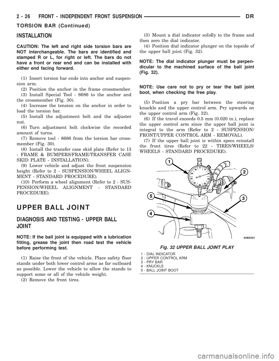
(2) Remove the front tires.(3) Mount a dial indicator solidly to the frame and
then zero the dial indicator.
(4) Position dial indicator plunger on the topside of
the upper ball joint (Fig. 32).
NOTE: The dial indicator plunger must be perpen-
dicular to the machined surface of the ball joint
(Fig. 32).
NOTE: Use care not to pry or tear the ball joint
boot, when checking the free play.
(5) Position a pry bar between the steering
knuckle and the upper control arm. Pry upwards on
the upper control arm (Fig. 32).
(6) If the travel exceeds 0.5 mm (0.020 in.), replace
the upper control arm since the upper ball joint is
integral to the arm (Refer to 2 - SUSPENSION/
FRONT/UPPER CONTROL ARM - REMOVAL).
(7) If the upper ball joint is within specs reinstall
the front tires (Refer to 22 - TIRES/WHEELS/
WHEELS - STANDARD PROCEDURE).
Fig. 32 UPPER BALL JOINT PLAY
1 - DIAL INDICATOR
2 - UPPER CONTROL ARM
3-PRYBAR
4 - KNUCKLE
5 - BALL JOINT BOOT
2 - 26 FRONT - INDEPENDENT FRONT SUSPENSIONDR
TORSION BAR (Continued)
Page 79 of 2895
SPECIFICATIONS
TORQUE SPECIFICATIONS
DESCRIPTION N´m Ft. Lbs. In. Lbs.
Center Bearing Bolts 54 40 -
Front Pinion Flange Bolts 115 85 -
Rear Pinion Flange Bolts 115 85 -
SPECIAL TOOLSFRONT PROPELLER SHAFT
REMOVAL
(1) Position transmission and transfer case into
neutral.
(2) Raise and support vehicle.
(3) Remove exhaust crossover pipe.
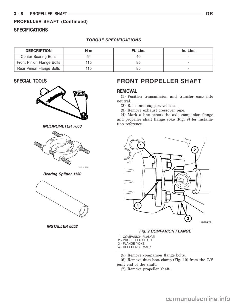
(4) Mark a line across the axle companion flange
and propeller shaft flange yoke (Fig. 9) for installa-
tion reference.
(5) Remove companion flange bolts.
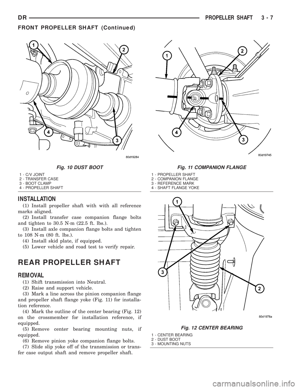
(6) Remove dust boot clamp (Fig. 10) from the C/V
jonit end of the shaft.
(7) Remove propeller shaft.
INCLINOMETER 7663
Bearing Splitter 1130
INSTALLER 6052
Fig. 9 COMPANION FLANGE
1 - COMPANION FLANGE
2 - PROPELLER SHAFT
3 - FLANGE YOKE
4 - REFERENCE MARK
3 - 6 PROPELLER SHAFTDR
PROPELLER SHAFT (Continued)
Page 80 of 2895
INSTALLATION
(1) Install propeller shaft with with all reference
marks aligned.
(2) Install transfer case companion flange bolts
and tighten to 30.5 N´m (22.5 ft. lbs.).
(3) Install axle companion flange bolts and tighten
to 108 N´m (80 ft. lbs.).
(4) Install skid plate, if equipped.
(5) Lower vehicle and road test to verify repair.
REAR PROPELLER SHAFT
REMOVAL
(1) Shift transmission into Neutral.
(2) Raise and support vehicle.
(3) Mark a line across the pinion companion flange
and propeller shaft flange yoke (Fig. 11) for installa-
tion reference.
(4) Mark the outline of the center bearing (Fig. 12)
on the crossmember for installation reference, if
equipped.
(5) Remove center bearing mounting nuts, if
equipped.
(6) Remove pinion yoke companion flange bolts.
(7) Slide slip yoke off of the transmission or trans-
fer case output shaft and remove propeller shaft.
Fig. 10 DUST BOOT
1 - C/V JOINT
2 - TRANSFER CASE
3 - BOOT CLAMP
4 - PROPELLER SHAFT
Fig. 11 COMPANION FLANGE
1 - PROPELLER SHAFT
2 - COMPANION FLANGE
3 - REFERENCE MARK
4 - SHAFT FLANGE YOKE
Fig. 12 CENTER BEARING
1 - CENTER BEARING
2 - DUST BOOT
3 - MOUNTING NUTS
DRPROPELLER SHAFT 3 - 7
FRONT PROPELLER SHAFT (Continued)
Page 81 of 2895
INSTALLATION
(1) Slide the slip yoke onto the transmission/trans-
fer case output shaft.
(2) Align and install center bearing on crossmem-
ber, if necessary and tighten nutts to 54 N´m (40 ft.
lbs.).
(3) Align reference marks on the propeller shaft
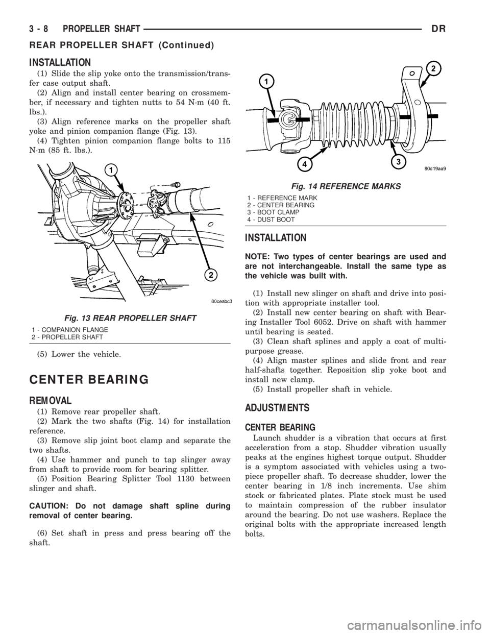
yoke and pinion companion flange (Fig. 13).
(4) Tighten pinion companion flange bolts to 115
N´m (85 ft. lbs.).
(5) Lower the vehicle.
CENTER BEARING
REMOVAL
(1) Remove rear propeller shaft.
(2) Mark the two shafts (Fig. 14) for installation
reference.
(3) Remove slip joint boot clamp and separate the
two shafts.
(4) Use hammer and punch to tap slinger away
from shaft to provide room for bearing splitter.
(5) Position Bearing Splitter Tool 1130 between
slinger and shaft.
CAUTION: Do not damage shaft spline during
removal of center bearing.
(6) Set shaft in press and press bearing off the
shaft.
INSTALLATION
NOTE: Two types of center bearings are used and
are not interchangeable. Install the same type as
the vehicle was built with.
(1) Install new slinger on shaft and drive into posi-
tion with appropriate installer tool.
(2) Install new center bearing on shaft with Bear-
ing Installer Tool 6052. Drive on shaft with hammer
until bearing is seated.
(3) Clean shaft splines and apply a coat of multi-
purpose grease.
(4) Align master splines and slide front and rear
half-shafts together. Reposition slip yoke boot and
install new clamp.
(5) Install propeller shaft in vehicle.
ADJUSTMENTS
CENTER BEARING
Launch shudder is a vibration that occurs at first
acceleration from a stop. Shudder vibration usually
peaks at the engines highest torque output. Shudder
is a symptom associated with vehicles using a two-
piece propeller shaft. To decrease shudder, lower the
center bearing in 1/8 inch increments. Use shim
stock or fabricated plates. Plate stock must be used
to maintain compression of the rubber insulator
around the bearing. Do not use washers. Replace the
original bolts with the appropriate increased length
bolts.
Fig. 13 REAR PROPELLER SHAFT
1 - COMPANION FLANGE
2 - PROPELLER SHAFT
Fig. 14 REFERENCE MARKS
1 - REFERENCE MARK
2 - CENTER BEARING
3 - BOOT CLAMP
4 - DUST BOOT
3 - 8 PROPELLER SHAFTDR
REAR PROPELLER SHAFT (Continued)
Page 84 of 2895
HALF SHAFT
TABLE OF CONTENTS
page page
HALF SHAFT
CAUTION.............................11
DIAGNOSIS AND TESTING................11
REMOVAL.............................11
INSTALLATION.........................12
SPECIFICATIONS.......................12
SPECIAL TOOLS.......................12CV JOINT-OUTER
REMOVAL.............................13
INSTALLATION.........................13
CV JOINT-INNER
REMOVAL.............................16
INSTALLATION.........................16
HALF SHAFT
CAUTION
CAUTION:: Never grasp half shaft assembly by the
boots. This may cause the boot to pucker or crease
and reduce the service life of the boot.
Avoid over angulating or stroking the C/V joints
when handling the half shaft.
Half shafts exposed to battery acid, transmission
fluid, brake fluid, differential fluid or gasoline may
cause the boots to deteriorate.
DIAGNOSIS AND TESTING
Check for grease at the inboard and outboard C/V
joint. This is a sign of boot or boot clamp damage.
NOISE/VIBRATION IN TURNS
A clicking noise or a vibration in turns could be
caused by a damaged outer C/V or inner tripod joint
seal boot or seal boot clamps. This will result in the
loss/contamination of the joint grease, resulting in
inadequate lubrication of the joint. Noise could also
be caused by another component of the vehicle com-
ing in contact with the half shafts.
CLUNKING NOISE DURING ACCELERATION
This noise may be a result of a damaged or worn
C/V joint. A torn boot or loose/missing clamp on the
inner/outer joint which has allowed the grease to be
lost will damage the C/V joint.
SHUDDER/VIBRATION DURING ACCELERATION
This problem could be a result of a worn/damaged
inner tripod joint or a sticking tripod joint. Improper
wheel alignment may also cause a shudder or vibra-
tion.
VIBRATION AT HIGHWAY SPEEDS
This problem could be a result of out of balance
front tires or tire/wheel runout. Foreign material
(mud, etc.) packed on the backside of the wheel(s)
will also cause a vibration.
REMOVAL
(1) Loosen lug nuts and hub nut while the with
the vehicle brakes applied.
(2) Raise and support the vehicle.
(3) Remove wheel and tire assembly
(4) Remove half shaft hub nut.
(5) Remove brake caliper and rotor.
(6) Position hydraulic jack under lower suspension
arm and raise jack to unload rebound bumper.
(7) Remove lower shock absorber bolt.
(8) Remove upper ball joint nut and seperate ball
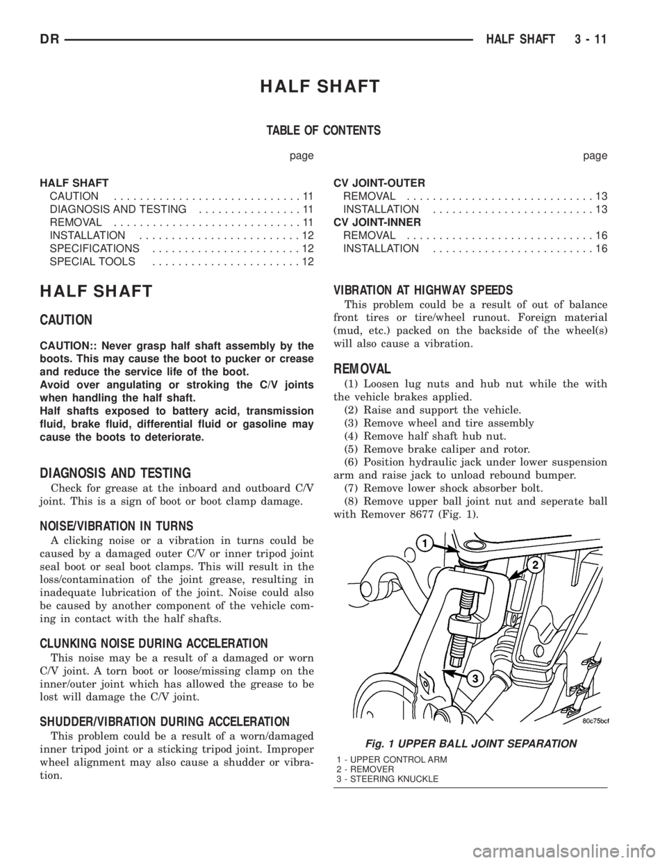
with Remover 8677 (Fig. 1).
Fig. 1 UPPER BALL JOINT SEPARATION
1 - UPPER CONTROL ARM
2 - REMOVER
3 - STEERING KNUCKLE
DRHALF SHAFT 3 - 11
Page 86 of 2895
CV JOINT-OUTER
REMOVAL
(1) Clamp shaft in a vise (with soft jaws) and sup-
port C/V joint.
(2) Remove clamps with a cut-off wheel or grinder
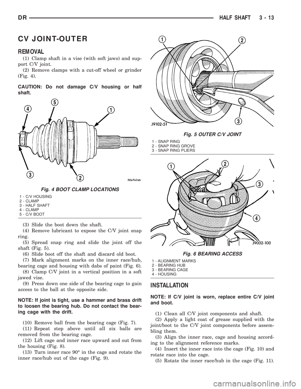
(Fig. 4).
CAUTION: Do not damage C/V housing or half
shaft.
(3) Slide the boot down the shaft.
(4) Remove lubricant to expose the C/V joint snap
ring.
(5) Spread snap ring and slide the joint off the
shaft (Fig. 5).
(6) Slide boot off the shaft and discard old boot.
(7) Mark alignment marks on the inner race/hub,
bearing cage and housing with dabs of paint (Fig. 6).
(8) Clamp C/V joint in a vertical position in a soft
jawed vise.
(9) Press down one side of the bearing cage to gain
access to the ball at the opposite side.
NOTE: If joint is tight, use a hammer and brass drift
to loosen the bearing hub. Do not contact the bear-
ing cage with the drift.
(10) Remove ball from the bearing cage (Fig. 7).
(11) Repeat step above until all six balls are
removed from the bearing cage.
(12) Lift cage and inner race upward and out from
the housing (Fig. 8).
(13) Turn inner race 90É in the cage and rotate the
inner race/hub out of the cage (Fig. 9).
INSTALLATION
NOTE: If C/V joint is worn, replace entire C/V joint
and boot.
(1) Clean all C/V joint components and shaft.
(2) Apply a light coat of grease supplied with the
joint/boot to the C/V joint components before assem-
bling them.
(3) Align the inner race, cage and housing accord-
ing to the alignment reference marks.
(4) Insert the inner race into the cage (Fig. 10) and
rotate race into the cage.
(5) Rotate the inner race/hub in the cage (Fig. 11).
Fig. 4 BOOT CLAMP LOCATIONS
1 - C/V HOUSING
2 - CLAMP
3 - HALF SHAFT
4 - CLAMP
5 - C/V BOOT
Fig. 5 OUTER C/V JOINT
1 - SNAP RING
2 - SNAP RING GROVE
3 - SNAP RING PLIERS
Fig. 6 BEARING ACCESS
1 - ALIGNMENT MARKS
2 - BEARING HUB
3 - BEARING CAGE
4 - HOUSING
DRHALF SHAFT 3 - 13
Page 87 of 2895
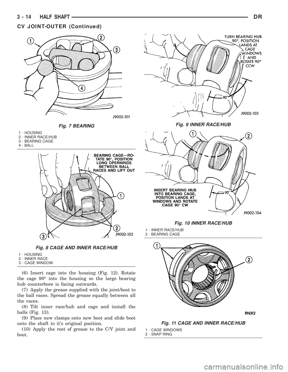
(6) Insert cage into the housing (Fig. 12). Rotate
the cage 90É into the housing so the large bearing
hub counterbore is facing outwards.
(7) Apply the grease supplied with the joint/boot to
the ball races. Spread the grease equally between all
the races.
(8) Tilt inner race/hub and cage and install the
balls (Fig. 13).
(9) Place new clamps onto new boot and slide boot
onto the shaft to it's original position.
(10) Apply the rest of grease to the C/V joint and
boot.
Fig. 7 BEARING
1 - HOUSING
2 - INNER RACE/HUB
3 - BEARING CAGE
4 - BALL
Fig. 8 CAGE AND INNER RACE/HUB
1 - HOUSING
2 - INNER RACE
3 - CAGE WINDOW
Fig. 9 INNER RACE/HUB
Fig. 10 INNER RACE/HUB
1 - INNER RACE/HUB
2 - BEARING CAGE
Fig. 11 CAGE AND INNER RACE/HUB
1 - CAGE WINDOWS
2 - SNAP RING
3 - 14 HALF SHAFTDR
CV JOINT-OUTER (Continued)
Page 88 of 2895
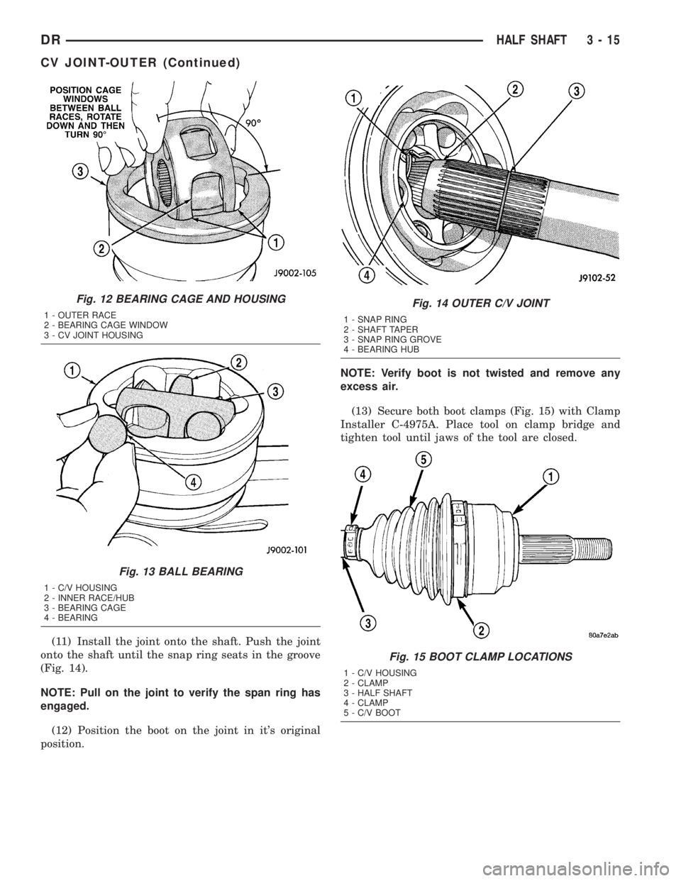
(11) Install the joint onto the shaft. Push the joint
onto the shaft until the snap ring seats in the groove
(Fig. 14).
NOTE: Pull on the joint to verify the span ring has
engaged.
(12) Position the boot on the joint in it's original
position.NOTE: Verify boot is not twisted and remove any
excess air.
(13) Secure both boot clamps (Fig. 15) with Clamp
Installer C-4975A. Place tool on clamp bridge and
tighten tool until jaws of the tool are closed.
Fig. 12 BEARING CAGE AND HOUSING
1 - OUTER RACE
2 - BEARING CAGE WINDOW
3 - CV JOINT HOUSING
Fig. 13 BALL BEARING
1 - C/V HOUSING
2 - INNER RACE/HUB
3 - BEARING CAGE
4 - BEARING
Fig. 14 OUTER C/V JOINT
1 - SNAP RING
2 - SHAFT TAPER
3 - SNAP RING GROVE
4 - BEARING HUB
Fig. 15 BOOT CLAMP LOCATIONS
1 - C/V HOUSING
2 - CLAMP
3 - HALF SHAFT
4 - CLAMP
5 - C/V BOOT
DRHALF SHAFT 3 - 15
CV JOINT-OUTER (Continued)
Page 89 of 2895
CV JOINT-INNER
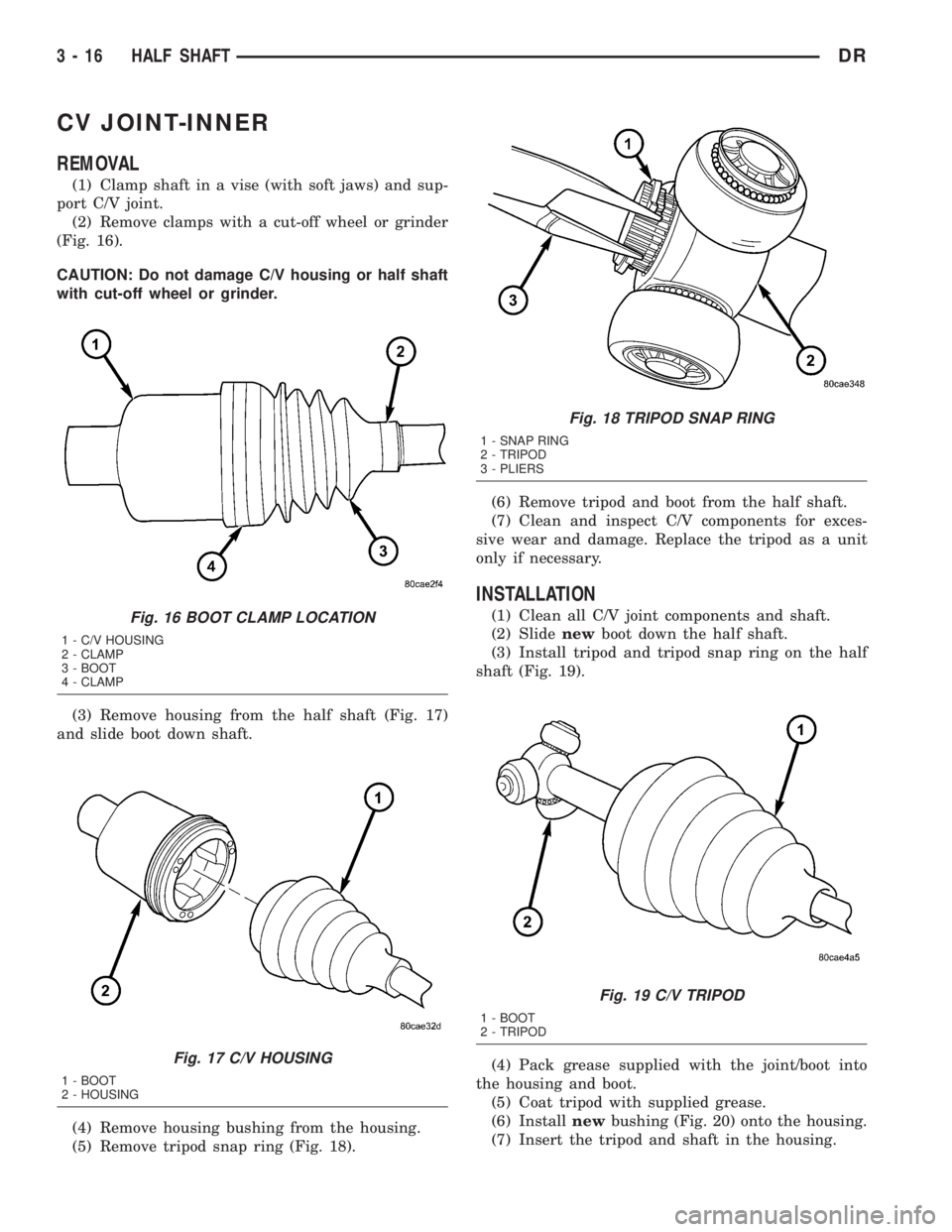
REMOVAL
(1) Clamp shaft in a vise (with soft jaws) and sup-
port C/V joint.
(2) Remove clamps with a cut-off wheel or grinder
(Fig. 16).
CAUTION: Do not damage C/V housing or half shaft
with cut-off wheel or grinder.
(3) Remove housing from the half shaft (Fig. 17)
and slide boot down shaft.
(4) Remove housing bushing from the housing.
(5) Remove tripod snap ring (Fig. 18).(6) Remove tripod and boot from the half shaft.
(7) Clean and inspect C/V components for exces-
sive wear and damage. Replace the tripod as a unit
only if necessary.
INSTALLATION
(1) Clean all C/V joint components and shaft.
(2) Slidenewboot down the half shaft.
(3) Install tripod and tripod snap ring on the half
shaft (Fig. 19).
(4) Pack grease supplied with the joint/boot into
the housing and boot.
(5) Coat tripod with supplied grease.
(6) Installnewbushing (Fig. 20) onto the housing.
(7) Insert the tripod and shaft in the housing.Fig. 16 BOOT CLAMP LOCATION
1 - C/V HOUSING
2 - CLAMP
3 - BOOT
4 - CLAMP
Fig. 17 C/V HOUSING
1 - BOOT
2 - HOUSING
Fig. 18 TRIPOD SNAP RING
1 - SNAP RING
2 - TRIPOD
3 - PLIERS
Fig. 19 C/V TRIPOD
1 - BOOT
2 - TRIPOD
3 - 16 HALF SHAFTDR