gas type DODGE RAM 2003 Service Repair Manual
[x] Cancel search | Manufacturer: DODGE, Model Year: 2003, Model line: RAM, Model: DODGE RAM 2003Pages: 2895, PDF Size: 83.15 MB
Page 6 of 2895
DIGIT 19
Price Class
²L = Low
²H = Highline
DIGITS 20 AND 21
Body Type
²41 = Ram Truck Quad Cab, Short Box
²42 = Ram Truck Quad Cab, Long Box
²61 = Ram Truck Standard Cab, Short Box
²62 = Ram Truck Standard Cab, Long Box
BODY CODE PLATEÐLINE 3
DIGITS 1,2, AND 3
Paint Procedure
²APA = Monotone
²AP9 = Special
²APD = Two-tone (Lower break)
DIGIT 4
Open Space
DIGITS 5 THROUGH 8
Primary Paint
(Refer to 23 - BODY/PAINT - SPECIFICATIONS)
for color codes.
DIGIT 9
Open Space
DIGITS 10 THROUGH 13
Secondary Paint
DIGIT 14
Open Space
DIGITS 15 THROUGH 18
Interior Trim Code
DIGIT 19
Open Space
DIGITS 20, 21, AND 22
Engine Code
²EKG = 3.7 L 6 cyl. MPI Gasoline
²EVA = 4.7 L 8 cyl. MPI Gasoline
²EZA = 5.7 L 8 cyl. SMPI Gasoline
²EML = 5.9 L 8 cyl. SMPI Gasoline
²ETC = 5.9 L 6 cyl. Cummins Turbo Diesel
²ETH = 5.9 L 6 cyl. Cummins Turbo Diesel High
Output
²EWA = 8.0 L 10 cyl. MPI Gasoline
BODY CODE PLATEÐLINE 2
DIGIT 1 Open Space
DIGITS 2 AND 3 Species Code. (Used for Manufacturing)
DIGIT 4
Open Space
DIGIT 5
Market Code
²B = International
²C = Canada
²M = Mexico
²U = United States
DIGIT 6
Open Space
DIGITS 7 THROUGH 23
Vehicle Identification Number (VIN)
(Refer to VEHICLE DATA/VEHICLE INFORMA-
TION/VEHICLE IDENTIFICATION NUMBER -
DESCRIPTION) for proper breakdown of VIN code.
BODY CODE PLATEÐLINE 1
DIGITS 1 THROUGH 6 Body-in-white assembly sequence.
DIGIT 7
Open Space
DIGIT 8 Tailgate trim code.
DIGIT 9
Open Space
DIGITS 10 THROUGH 12 Cargo box code
DIGIT 13
Open Space
DIGITS 14 THROUGH 16 Tailgate code
DRINTRODUCTION 5
BODY CODE PLATE (Continued)
Page 14 of 2895
LUBRICATION & MAINTENANCE
TABLE OF CONTENTS
page page
INTERNATIONAL SYMBOLS
DESCRIPTION..........................1
FLUID TYPES
DESCRIPTION
DESCRIPTION - FUEL REQUIREMENTS -
DIESEL ENGINE.......................1
DESCRIPTION - ENGINE OIL AND
LUBRICANTS.........................2
DESCRIPTION - POWER STEERING FLUID . . 3
DESCRIPTION - ENGINE COOLANT........3
DESCRIPTION - TRANSFER CASE - NV241
GENII...............................4
DESCRIPTION - TRANSFER CASE - NV271 . . 4
DESCRIPTION - TRANSFER CASE - NV243 . . 4
DESCRIPTION - TRANSFER CASE - NV273 . . 4
DESCRIPTION - AXLE...................4DESCRIPTION - MANUAL TRANSMISSION . . . 4
DESCRIPTION - AUTOMATIC
TRANSMISSION FLUID..................4
OPERATION - AUTOMATIC TRANSMISSION
FLUID...............................5
FLUID CAPACITIES
SPECIFICATIONS
FLUID CAPACITIES.....................5
MAINTENANCE SCHEDULES
DESCRIPTION..........................6
JUMP STARTING
STANDARD PROCEDURE - JUMP STARTING...13
HOISTING
STANDARD PROCEDURE - HOISTING.......14
TOWING
STANDARD PROCEDURE - TOWING........15
INTERNATIONAL SYMBOLS
DESCRIPTION
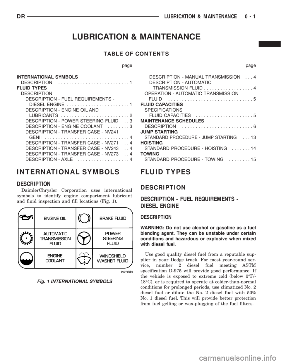
DaimlerChrysler Corporation uses international
symbols to identify engine compartment lubricant
and fluid inspection and fill locations (Fig. 1).
FLUID TYPES
DESCRIPTION
DESCRIPTION - FUEL REQUIREMENTS -
DIESEL ENGINE
DESCRIPTION
WARNING: Do not use alcohol or gasoline as a fuel
blending agent. They can be unstable under certain
conditions and hazardous or explosive when mixed
with diesel fuel.
Use good quality diesel fuel from a reputable sup-
plier in your Dodge truck. For most year-round ser-
vice, number 2 diesel fuel meeting ASTM
specification D-975 will provide good performance. If
the vehicle is exposed to extreme cold (below 0ÉF/-
18ÉC), or is required to operate at colder-than-normal
conditions for prolonged periods, use climatized No. 2
diesel fuel or dilute the No. 2 diesel fuel with 50%
No. 1 diesel fuel. This will provide better protection
from fuel gelling or wax-plugging of the fuel filters.
Fig. 1 INTERNATIONAL SYMBOLS
DRLUBRICATION & MAINTENANCE 0 - 1
Page 15 of 2895
Diesel fuel is seldom completely free of water. To
prevent fuel system trouble, including fuel line freez-
ing in winter, drain the accumulated water from the
fuel/water separator using the fuel/water separator
drain provided. If you buy good-quality fuel and fol-
low the cold-weather advice above, fuel conditioners
should not be required in your vehicle. If available in
your area, a high cetane ªpremiumº diesel fuel may
offer improved cold starting and warm-up perfor-
mance.
DESCRIPTION - ENGINE OIL AND LUBRICANTS
WARNING: NEW OR USED ENGINE OIL CAN BE
IRRITATING TO THE SKIN. AVOID PROLONGED OR
REPEATED SKIN CONTACT WITH ENGINE OIL.
CONTAMINANTS IN USED ENGINE OIL, CAUSED BY
INTERNAL COMBUSTION, CAN BE HAZARDOUS TO
YOUR HEALTH. THOROUGHLY WASH EXPOSED
SKIN WITH SOAP AND WATER. DO NOT WASH
SKIN WITH GASOLINE, DIESEL FUEL, THINNER, OR
SOLVENTS, HEALTH PROBLEMS CAN RESULT. DO
NOT POLLUTE, DISPOSE OF USED ENGINE OIL
PROPERLY. CONTACT YOUR DEALER OR GOVERN-
MENT AGENCY FOR LOCATION OF COLLECTION
CENTER IN YOUR AREA.
When service is required, DaimlerChrysler Corpo-
ration recommends that only Mopartbrand parts,
lubricants and chemicals be used. Mopartprovides
the best engineered products for servicing
DaimlerChrysler Corporation vehicles.
Only lubricants bearing designations defined by
the following organization should be used.
²Society of Automotive Engineers (SAE)
²American Petroleum Institute (API)
²National Lubricating Grease Institute (NLGI)
API SERVICE GRADE CERTIFIED
Use an engine oil that is API Certified. MOPARt
provides engine oils, that meet or exceed this
requirement.
SAE VISCOSITY
An SAE viscosity grade is used to specify the vis-
cosity of engine oil. Use only engine oils with multi-
ple viscosities such as 5W-30 or 10W-30. These are
specified with a dual SAE viscosity grade which indi-
cates the cold-to-hot temperature viscosity range.
Select an engine oil that is best suited to your par-
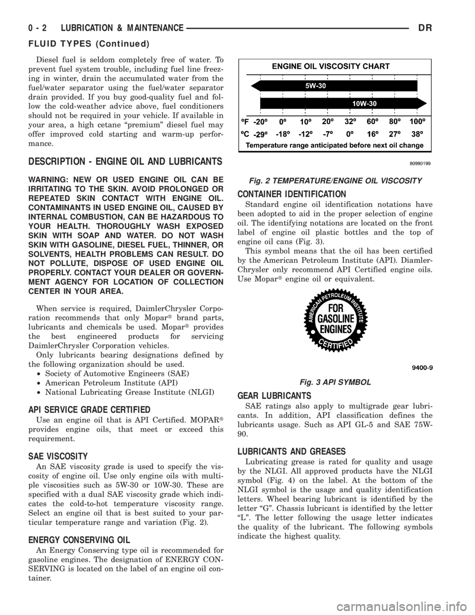
ticular temperature range and variation (Fig. 2).
ENERGY CONSERVING OIL
An Energy Conserving type oil is recommended for
gasoline engines. The designation of ENERGY CON-
SERVING is located on the label of an engine oil con-
tainer.
CONTAINER IDENTIFICATION
Standard engine oil identification notations have
been adopted to aid in the proper selection of engine
oil. The identifying notations are located on the front
label of engine oil plastic bottles and the top of
engine oil cans (Fig. 3).
This symbol means that the oil has been certified
by the American Petroleum Institute (API). Diamler-
Chrysler only recommend API Certified engine oils.
Use Mopartengine oil or equivalent.
GEAR LUBRICANTS
SAE ratings also apply to multigrade gear lubri-
cants. In addition, API classification defines the
lubricants usage. Such as API GL-5 and SAE 75W-
90.
LUBRICANTS AND GREASES
Lubricating grease is rated for quality and usage
by the NLGI. All approved products have the NLGI
symbol (Fig. 4) on the label. At the bottom of the
NLGI symbol is the usage and quality identification
letters. Wheel bearing lubricant is identified by the
letter ªGº. Chassis lubricant is identified by the letter
ªLº. The letter following the usage letter indicates
the quality of the lubricant. The following symbols
indicate the highest quality.
Fig. 2 TEMPERATURE/ENGINE OIL VISCOSITY
Fig. 3 API SYMBOL
0 - 2 LUBRICATION & MAINTENANCEDR
FLUID TYPES (Continued)
Page 137 of 2895
(7) Back off the ring gear side adjuster 4 holes, to
obtain initial ring gear backlash.
(8) Install ring gear side adjuster lock and bolt. Do
not tighten adjuster lock bolt at this time.
(9) Tighten pinion gear side adjuster firmly
against the differential case bearing cup.
(10) Rotate the pinion several times to seat the dif-
ferential bearings.
(11) Loosen pinion gear side adjuster until it is no
longer in contact with the bearing cup.
(12) Tighten pinion gear side adjuster until it just
makes contact with the bearing cup.
(13) Tighten pinion gear side adjuster an addi-
tional:
²New Bearings:6 Adjuster Holes
²Original Bearings:4 Adjuster Holes
(14) Install pinion gear side adjuster lock and bolt.
Do not tighten adjuster lock bolt at this time.
(15) Tighten bearing cap bolts to 85 N´m (63 ft.
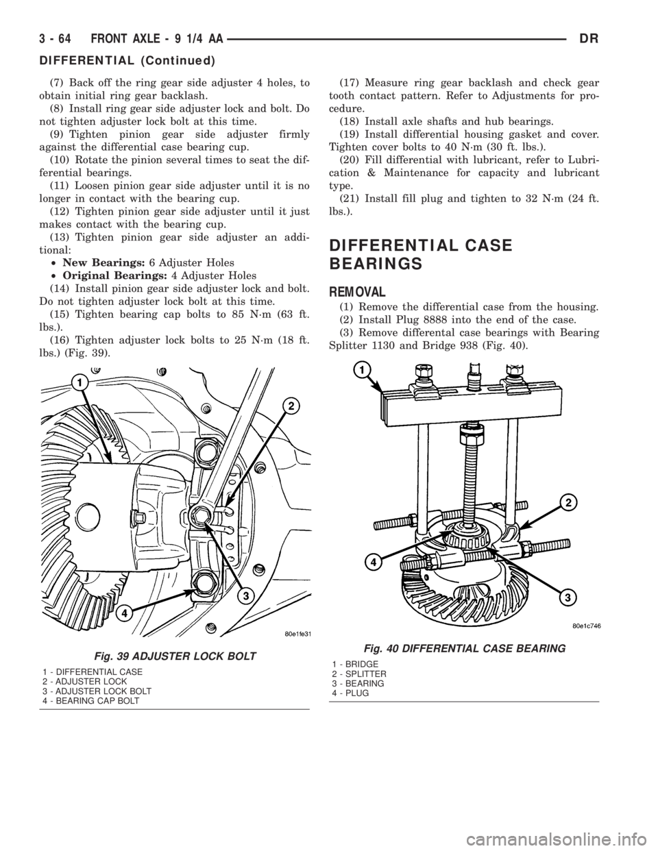
lbs.).
(16) Tighten adjuster lock bolts to 25 N´m (18 ft.
lbs.) (Fig. 39).(17) Measure ring gear backlash and check gear
tooth contact pattern. Refer to Adjustments for pro-
cedure.
(18) Install axle shafts and hub bearings.
(19) Install differential housing gasket and cover.
Tighten cover bolts to 40 N´m (30 ft. lbs.).
(20) Fill differential with lubricant, refer to Lubri-
cation & Maintenance for capacity and lubricant
type.
(21) Install fill plug and tighten to 32 N´m (24 ft.
lbs.).
DIFFERENTIAL CASE
BEARINGS
REMOVAL
(1) Remove the differential case from the housing.
(2) Install Plug 8888 into the end of the case.
(3) Remove differental case bearings with Bearing
Splitter 1130 and Bridge 938 (Fig. 40).
Fig. 39 ADJUSTER LOCK BOLT
1 - DIFFERENTIAL CASE
2 - ADJUSTER LOCK
3 - ADJUSTER LOCK BOLT
4 - BEARING CAP BOLT
Fig. 40 DIFFERENTIAL CASE BEARING
1 - BRIDGE
2 - SPLITTER
3 - BEARING
4 - PLUG
3 - 64 FRONT AXLE - 9 1/4 AADR
DIFFERENTIAL (Continued)
Page 191 of 2895
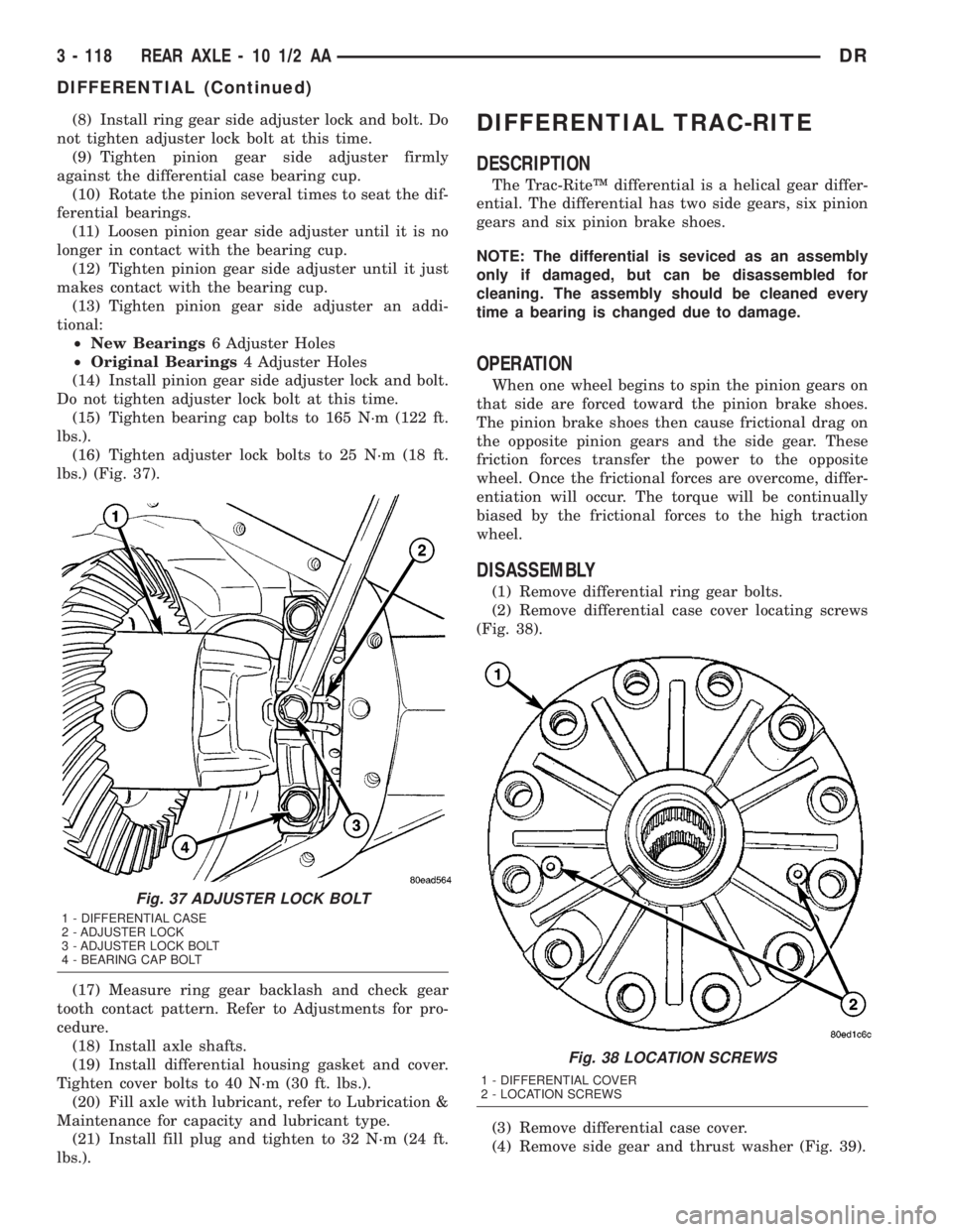
(8) Install ring gear side adjuster lock and bolt. Do
not tighten adjuster lock bolt at this time.
(9) Tighten pinion gear side adjuster firmly
against the differential case bearing cup.
(10) Rotate the pinion several times to seat the dif-
ferential bearings.
(11) Loosen pinion gear side adjuster until it is no
longer in contact with the bearing cup.
(12) Tighten pinion gear side adjuster until it just
makes contact with the bearing cup.
(13) Tighten pinion gear side adjuster an addi-
tional:
²New Bearings6 Adjuster Holes
²Original Bearings4 Adjuster Holes
(14) Install pinion gear side adjuster lock and bolt.
Do not tighten adjuster lock bolt at this time.
(15) Tighten bearing cap bolts to 165 N´m (122 ft.
lbs.).
(16) Tighten adjuster lock bolts to 25 N´m (18 ft.
lbs.) (Fig. 37).
(17) Measure ring gear backlash and check gear
tooth contact pattern. Refer to Adjustments for pro-
cedure.
(18) Install axle shafts.
(19) Install differential housing gasket and cover.
Tighten cover bolts to 40 N´m (30 ft. lbs.).
(20) Fill axle with lubricant, refer to Lubrication &
Maintenance for capacity and lubricant type.
(21) Install fill plug and tighten to 32 N´m (24 ft.
lbs.).DIFFERENTIAL TRAC-RITE
DESCRIPTION
The Trac-RiteŸ differential is a helical gear differ-
ential. The differential has two side gears, six pinion
gears and six pinion brake shoes.
NOTE: The differential is seviced as an assembly
only if damaged, but can be disassembled for
cleaning. The assembly should be cleaned every
time a bearing is changed due to damage.
OPERATION
When one wheel begins to spin the pinion gears on
that side are forced toward the pinion brake shoes.
The pinion brake shoes then cause frictional drag on
the opposite pinion gears and the side gear. These
friction forces transfer the power to the opposite
wheel. Once the frictional forces are overcome, differ-
entiation will occur. The torque will be continually
biased by the frictional forces to the high traction
wheel.
DISASSEMBLY
(1) Remove differential ring gear bolts.
(2) Remove differential case cover locating screws
(Fig. 38).
(3) Remove differential case cover.
(4) Remove side gear and thrust washer (Fig. 39).
Fig. 37 ADJUSTER LOCK BOLT
1 - DIFFERENTIAL CASE
2 - ADJUSTER LOCK
3 - ADJUSTER LOCK BOLT
4 - BEARING CAP BOLT
Fig. 38 LOCATION SCREWS
1 - DIFFERENTIAL COVER
2 - LOCATION SCREWS
3 - 118 REAR AXLE - 10 1/2 AADR
DIFFERENTIAL (Continued)
Page 218 of 2895
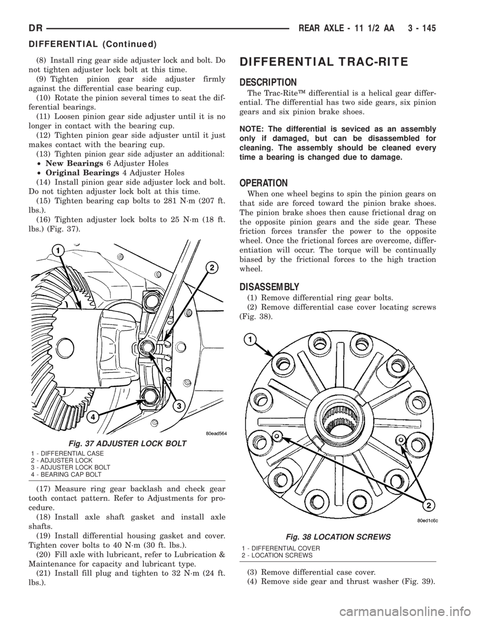
(8) Install ring gear side adjuster lock and bolt. Do
not tighten adjuster lock bolt at this time.
(9) Tighten pinion gear side adjuster firmly
against the differential case bearing cup.
(10) Rotate the pinion several times to seat the dif-
ferential bearings.
(11) Loosen pinion gear side adjuster until it is no
longer in contact with the bearing cup.
(12) Tighten pinion gear side adjuster until it just
makes contact with the bearing cup.
(13)
Tighten pinion gear side adjuster an additional:
²New Bearings6 Adjuster Holes
²Original Bearings4 Adjuster Holes
(14) Install pinion gear side adjuster lock and bolt.
Do not tighten adjuster lock bolt at this time.
(15) Tighten bearing cap bolts to 281 N´m (207 ft.
lbs.).
(16) Tighten adjuster lock bolts to 25 N´m (18 ft.
lbs.) (Fig. 37).
(17) Measure ring gear backlash and check gear
tooth contact pattern. Refer to Adjustments for pro-
cedure.
(18) Install axle shaft gasket and install axle
shafts.
(19) Install differential housing gasket and cover.
Tighten cover bolts to 40 N´m (30 ft. lbs.).
(20) Fill axle with lubricant, refer to Lubrication &
Maintenance for capacity and lubricant type.
(21) Install fill plug and tighten to 32 N´m (24 ft.
lbs.).
DIFFERENTIAL TRAC-RITE
DESCRIPTION
The Trac-RiteŸ differential is a helical gear differ-
ential. The differential has two side gears, six pinion
gears and six pinion brake shoes.
NOTE: The differential is seviced as an assembly
only if damaged, but can be disassembled for
cleaning. The assembly should be cleaned every
time a bearing is changed due to damage.
OPERATION
When one wheel begins to spin the pinion gears on
that side are forced toward the pinion brake shoes.
The pinion brake shoes then cause frictional drag on
the opposite pinion gears and the side gear. These
friction forces transfer the power to the opposite
wheel. Once the frictional forces are overcome, differ-
entiation will occur. The torque will be continually
biased by the frictional forces to the high traction
wheel.
DISASSEMBLY
(1) Remove differential ring gear bolts.
(2) Remove differential case cover locating screws
(Fig. 38).
(3) Remove differential case cover.
(4) Remove side gear and thrust washer (Fig. 39).
Fig. 37 ADJUSTER LOCK BOLT
1 - DIFFERENTIAL CASE
2 - ADJUSTER LOCK
3 - ADJUSTER LOCK BOLT
4 - BEARING CAP BOLT
Fig. 38 LOCATION SCREWS
1 - DIFFERENTIAL COVER
2 - LOCATION SCREWS
DRREAR AXLE - 11 1/2 AA 3 - 145
DIFFERENTIAL (Continued)
Page 234 of 2895
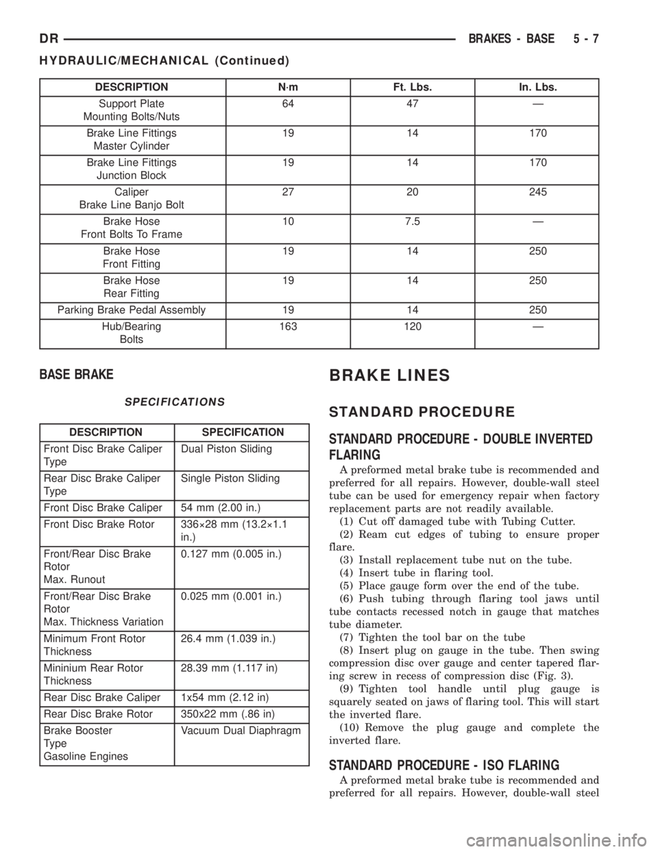
DESCRIPTION N´m Ft. Lbs. In. Lbs.
Support Plate
Mounting Bolts/Nuts64 47 Ð
Brake Line Fittings
Master Cylinder19 14 170
Brake Line Fittings
Junction Block19 14 170
Caliper
Brake Line Banjo Bolt27 20 245
Brake Hose
Front Bolts To Frame10 7.5 Ð
Brake Hose
Front Fitting19 14 250
Brake Hose
Rear Fitting19 14 250
Parking Brake Pedal Assembly 19 14 250
Hub/Bearing
Bolts163 120 Ð
BASE BRAKE
SPECIFICATIONS
DESCRIPTION SPECIFICATION
Front Disc Brake Caliper
TypeDual Piston Sliding
Rear Disc Brake Caliper
TypeSingle Piston Sliding
Front Disc Brake Caliper 54 mm (2.00 in.)
Front Disc Brake Rotor 336ý28 mm (13.2ý1.1
in.)
Front/Rear Disc Brake
Rotor
Max. Runout0.127 mm (0.005 in.)
Front/Rear Disc Brake
Rotor
Max. Thickness Variation0.025 mm (0.001 in.)
Minimum Front Rotor
Thickness26.4 mm (1.039 in.)
Mininium Rear Rotor
Thickness28.39 mm (1.117 in)
Rear Disc Brake Caliper 1x54 mm (2.12 in)
Rear Disc Brake Rotor 350x22 mm (.86 in)
Brake Booster
Type
Gasoline EnginesVacuum Dual Diaphragm
BRAKE LINES
STANDARD PROCEDURE
STANDARD PROCEDURE - DOUBLE INVERTED
FLARING
A preformed metal brake tube is recommended and
preferred for all repairs. However, double-wall steel
tube can be used for emergency repair when factory
replacement parts are not readily available.
(1) Cut off damaged tube with Tubing Cutter.
(2) Ream cut edges of tubing to ensure proper
flare.
(3) Install replacement tube nut on the tube.
(4) Insert tube in flaring tool.
(5) Place gauge form over the end of the tube.
(6) Push tubing through flaring tool jaws until
tube contacts recessed notch in gauge that matches
tube diameter.
(7) Tighten the tool bar on the tube
(8) Insert plug on gauge in the tube. Then swing
compression disc over gauge and center tapered flar-
ing screw in recess of compression disc (Fig. 3).
(9) Tighten tool handle until plug gauge is
squarely seated on jaws of flaring tool. This will start
the inverted flare.
(10) Remove the plug gauge and complete the
inverted flare.
STANDARD PROCEDURE - ISO FLARING
A preformed metal brake tube is recommended and
preferred for all repairs. However, double-wall steel
DRBRAKES - BASE 5 - 7
HYDRAULIC/MECHANICAL (Continued)
Page 292 of 2895
system is pressurized and uses a centrifugal water
pump to circulate coolant throughout the system.
5.9L, 5.9L Diesel, and 8.0L engines utilize an
ambient overflow bottle for coolant recovery/reserve.
The 3.7L and 4.7L engines utilize a pressurized
degas bottle for coolant deaeration and reserve. This
degas bottle has coolant flowing through it continu-
ously, supplied by a vent in the hot side radiator
tank and returning to the heater return hose.
An optional factory installed maximum duty cool-
ing package is available on most models. This pack-
age will provide additional cooling capacity for
vehicles used under extreme conditions such as
trailer towing in high ambient temperatures.
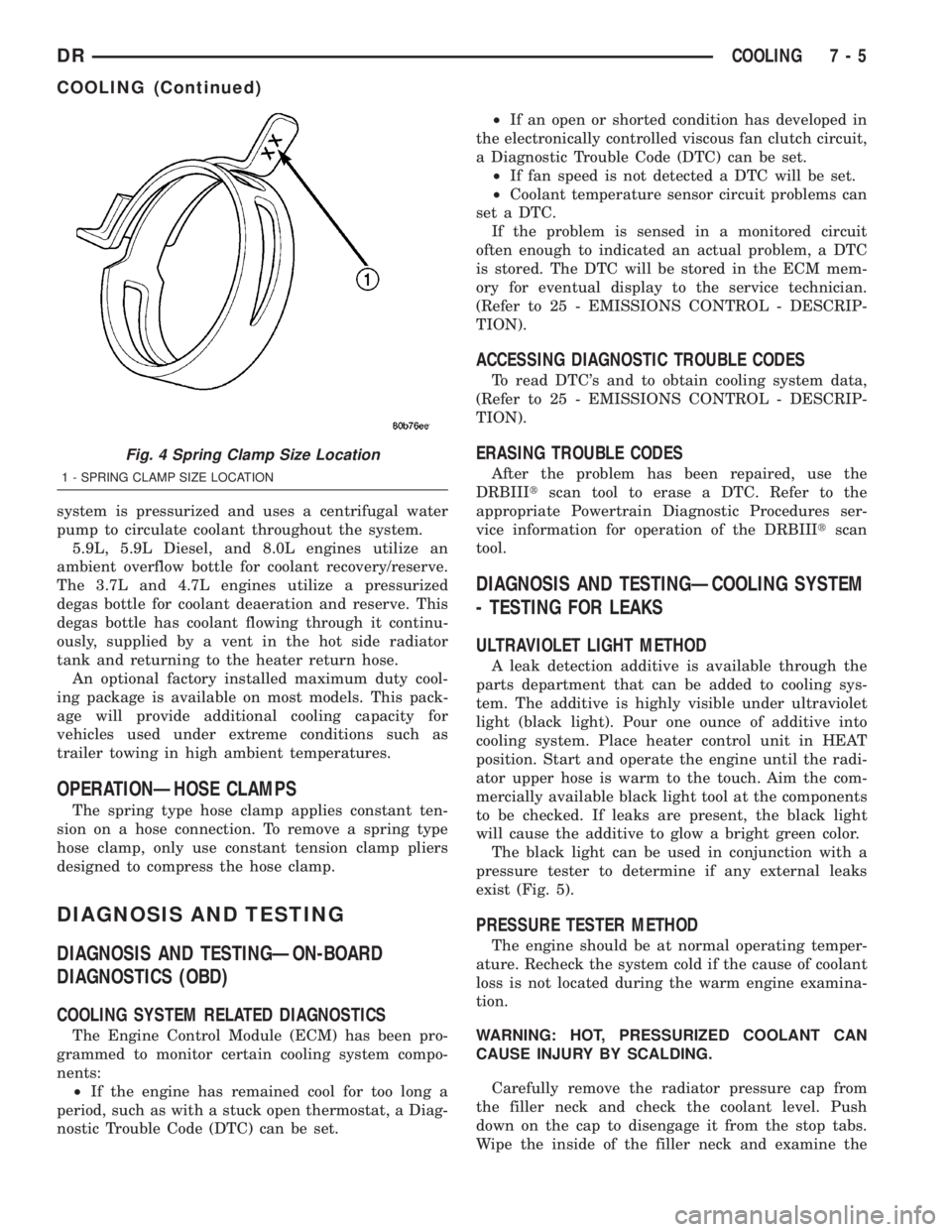
OPERATIONÐHOSE CLAMPS
The spring type hose clamp applies constant ten-
sion on a hose connection. To remove a spring type
hose clamp, only use constant tension clamp pliers
designed to compress the hose clamp.
DIAGNOSIS AND TESTING
DIAGNOSIS AND TESTINGÐON-BOARD
DIAGNOSTICS (OBD)
COOLING SYSTEM RELATED DIAGNOSTICS
The Engine Control Module (ECM) has been pro-
grammed to monitor certain cooling system compo-
nents:
²If the engine has remained cool for too long a
period, such as with a stuck open thermostat, a Diag-
nostic Trouble Code (DTC) can be set.²If an open or shorted condition has developed in
the electronically controlled viscous fan clutch circuit,
a Diagnostic Trouble Code (DTC) can be set.
²If fan speed is not detected a DTC will be set.
²Coolant temperature sensor circuit problems can
set a DTC.
If the problem is sensed in a monitored circuit
often enough to indicated an actual problem, a DTC
is stored. The DTC will be stored in the ECM mem-
ory for eventual display to the service technician.
(Refer to 25 - EMISSIONS CONTROL - DESCRIP-
TION).
ACCESSING DIAGNOSTIC TROUBLE CODES
To read DTC's and to obtain cooling system data,
(Refer to 25 - EMISSIONS CONTROL - DESCRIP-
TION).
ERASING TROUBLE CODES
After the problem has been repaired, use the
DRBIIItscan tool to erase a DTC. Refer to the
appropriate Powertrain Diagnostic Procedures ser-
vice information for operation of the DRBIIItscan
tool.
DIAGNOSIS AND TESTINGÐCOOLING SYSTEM
- TESTING FOR LEAKS
ULTRAVIOLET LIGHT METHOD
A leak detection additive is available through the
parts department that can be added to cooling sys-
tem. The additive is highly visible under ultraviolet
light (black light). Pour one ounce of additive into
cooling system. Place heater control unit in HEAT
position. Start and operate the engine until the radi-
ator upper hose is warm to the touch. Aim the com-
mercially available black light tool at the components
to be checked. If leaks are present, the black light
will cause the additive to glow a bright green color.
The black light can be used in conjunction with a
pressure tester to determine if any external leaks
exist (Fig. 5).
PRESSURE TESTER METHOD
The engine should be at normal operating temper-
ature. Recheck the system cold if the cause of coolant
loss is not located during the warm engine examina-
tion.
WARNING: HOT, PRESSURIZED COOLANT CAN
CAUSE INJURY BY SCALDING.
Carefully remove the radiator pressure cap from
the filler neck and check the coolant level. Push
down on the cap to disengage it from the stop tabs.
Wipe the inside of the filler neck and examine the
Fig. 4 Spring Clamp Size Location
1 - SPRING CLAMP SIZE LOCATION
DRCOOLING 7 - 5
COOLING (Continued)
Page 299 of 2895
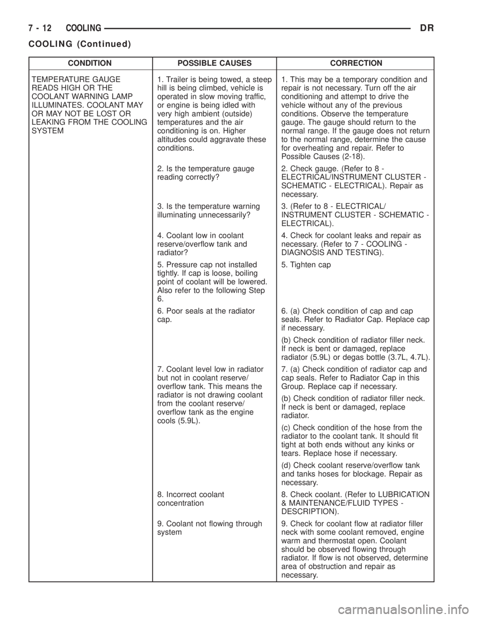
CONDITION POSSIBLE CAUSES CORRECTION
TEMPERATURE GAUGE
READS HIGH OR THE
COOLANT WARNING LAMP
ILLUMINATES. COOLANT MAY
OR MAY NOT BE LOST OR
LEAKING FROM THE COOLING
SYSTEM1. Trailer is being towed, a steep
hill is being climbed, vehicle is
operated in slow moving traffic,
or engine is being idled with
very high ambient (outside)
temperatures and the air
conditioning is on. Higher
altitudes could aggravate these
conditions.1. This may be a temporary condition and
repair is not necessary. Turn off the air
conditioning and attempt to drive the
vehicle without any of the previous
conditions. Observe the temperature
gauge. The gauge should return to the
normal range. If the gauge does not return
to the normal range, determine the cause
for overheating and repair. Refer to
Possible Causes (2-18).
2. Is the temperature gauge
reading correctly?2. Check gauge. (Refer to 8 -
ELECTRICAL/INSTRUMENT CLUSTER -
SCHEMATIC - ELECTRICAL). Repair as
necessary.
3. Is the temperature warning
illuminating unnecessarily?3. (Refer to 8 - ELECTRICAL/
INSTRUMENT CLUSTER - SCHEMATIC -
ELECTRICAL).
4. Coolant low in coolant
reserve/overflow tank and
radiator?4. Check for coolant leaks and repair as
necessary. (Refer to 7 - COOLING -
DIAGNOSIS AND TESTING).
5. Pressure cap not installed
tightly. If cap is loose, boiling
point of coolant will be lowered.
Also refer to the following Step
6.5. Tighten cap
6. Poor seals at the radiator
cap.6. (a) Check condition of cap and cap
seals. Refer to Radiator Cap. Replace cap
if necessary.
(b) Check condition of radiator filler neck.
If neck is bent or damaged, replace
radiator (5.9L) or degas bottle (3.7L, 4.7L).
7. Coolant level low in radiator
but not in coolant reserve/
overflow tank. This means the
radiator is not drawing coolant
from the coolant reserve/
overflow tank as the engine
cools (5.9L).7. (a) Check condition of radiator cap and
cap seals. Refer to Radiator Cap in this
Group. Replace cap if necessary.
(b) Check condition of radiator filler neck.
If neck is bent or damaged, replace
radiator.
(c) Check condition of the hose from the
radiator to the coolant tank. It should fit
tight at both ends without any kinks or
tears. Replace hose if necessary.
(d) Check coolant reserve/overflow tank
and tanks hoses for blockage. Repair as
necessary.
8. Incorrect coolant
concentration8. Check coolant. (Refer to LUBRICATION
& MAINTENANCE/FLUID TYPES -
DESCRIPTION).
9. Coolant not flowing through
system9. Check for coolant flow at radiator filler
neck with some coolant removed, engine
warm and thermostat open. Coolant
should be observed flowing through
radiator. If flow is not observed, determine
area of obstruction and repair as
necessary.
7 - 12 COOLINGDR
COOLING (Continued)
Page 333 of 2895
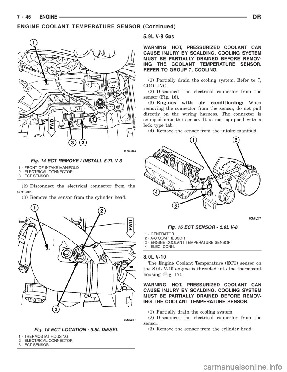
(2) Disconnect the electrical connector from the
sensor.
(3) Remove the sensor from the cylinder head.
5.9L V-8 Gas
WARNING: HOT, PRESSURIZED COOLANT CAN
CAUSE INJURY BY SCALDING. COOLING SYSTEM
MUST BE PARTIALLY DRAINED BEFORE REMOV-
ING THE COOLANT TEMPERATURE SENSOR.
REFER TO GROUP 7, COOLING.
(1) Partially drain the cooling system. Refer to 7,
COOLING.
(2) Disconnect the electrical connector from the
sensor (Fig. 16).
(3)Engines with air conditioning:When
removing the connector from the sensor, do not pull
directly on the wiring harness. The connector is
snapped onto the sensor. It is not equipped with a
lock type tab.
(4) Remove the sensor from the intake manifold.
8.0L V-10
The Engine Coolant Temperature (ECT) sensor on
the 8.0L V-10 engine is threaded into the thermostat
housing (Fig. 17).
WARNING: HOT, PRESSURIZED COOLANT CAN
CAUSE INJURY BY SCALDING. COOLING SYSTEM
MUST BE PARTIALLY DRAINED BEFORE REMOV-
ING THE COOLANT TEMPERATURE SENSOR.
(1) Partially drain the cooling system.
(2) Disconnect the electrical connector from the
sensor.
(3) Remove the sensor from the cylinder head.
Fig. 14 ECT REMOVE / INSTALL 5.7L V-8
1 - FRONT OF INTAKE MANIFOLD
2 - ELECTRICAL CONNECTOR
3 - ECT SENSOR
Fig. 15 ECT LOCATION - 5.9L DIESEL
1 - THERMOSTAT HOUSING
2 - ELECTRICAL CONNECTOR
3 - ECT SENSOR
Fig. 16 ECT SENSOR - 5.9L V-8
1 - GENERATOR
2 - A/C COMPRESSOR
3 - ENGINE COOLANT TEMPERATURE SENSOR
4 - ELEC. CONN.
7 - 46 ENGINEDR
ENGINE COOLANT TEMPERATURE SENSOR (Continued)