run flat DODGE RAM 2003 Service Repair Manual
[x] Cancel search | Manufacturer: DODGE, Model Year: 2003, Model line: RAM, Model: DODGE RAM 2003Pages: 2895, PDF Size: 83.15 MB
Page 76 of 2895
(15) If the vibration remains unacceptable, apply
the same steps to the front end of the propeller shaft.
(16) Install the wheel and tires. Lower the vehicle.
PROPELLER SHAFT RUNOUT
(1) Remove dirt, rust, paint and undercoating from
the propeller shaft surface where the dial indicator
will contact the shaft.
(2) The dial indicator must be installed perpendic-
ular to the shaft surface.
(3) Measure runout at the center and ends of the
shaft sufficiently far away from weld areas to ensure
that the effects of the weld process will not enter into
the measurements.
(4) Refer to Runout Specifications chart.
(5) If the propeller shaft runout is out of specifica-
tion, remove the propeller shaft, index the shaft 180É,
and re-install the propeller shaft. Measure shaft
runout again.
(6) If the propeller shaft runout is now within
specifications, mark the shaft and yokes for proper
orientation.
(7) If the propeller shaft runout is not within spec-
ifications, verify that the runout of the transmission/
transfer case and axle are within specifications.
Correct as necessary and re-measure propeller shaft
runout.
(8) Replace the propeller shaft if the runout still
exceeds the limits.
RUNOUT SPECIFICATIONS
Front of Shaft 0.020 in. (0.50 mm)
Center of Shaft 0.025 in. (0.63 mm)
Rear of Shaft 0.020 in. (0.50 mm)
note:
Measure front/rear runout approximately 3 inches (76
mm) from the weld seam at each end of the shaft
tube for tube lengths over 30 inches. For tube lengths
under 30 inches, the maximum allowed runout is
0.020 in. (0.50 mm) for the full length of the tube.
STANDARD PROCEDURE
PROPELLER SHAFT ANGLE
This procedure applies to both the front/rear pro-
peller shafts. To obtain the front output angle (A) on
the front propeller shaft, place the inclinometer the
machined surface of the C/V joint.
(1) To check driveline alignment, raise and support
the vehicle at the axles as level as possible. Allow the
wheels and propeller shaft to turn.
(2) Remove any external bearing snap rings, if
equipped from universal joint so protractor base sits
flat.
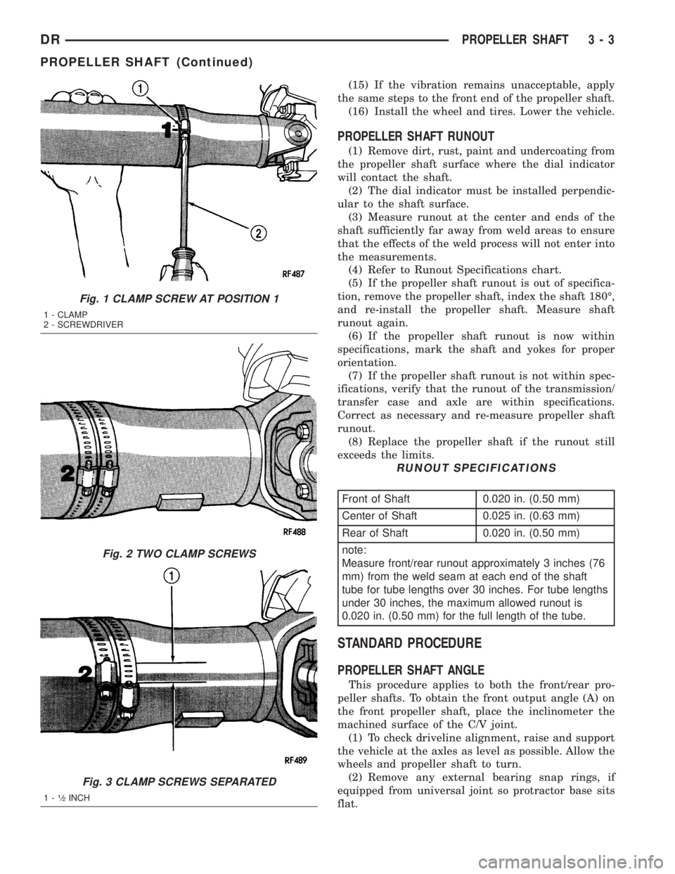
Fig. 1 CLAMP SCREW AT POSITION 1
1 - CLAMP
2 - SCREWDRIVER
Fig. 2 TWO CLAMP SCREWS
Fig. 3 CLAMP SCREWS SEPARATED
1-1¤2INCH
DRPROPELLER SHAFT 3 - 3
PROPELLER SHAFT (Continued)
Page 594 of 2895
The individual switches in the power seat switch
assembly cannot be repaired. If one switch is dam-
aged or faulty, the entire power seat switch assembly
must be replaced.
OPERATION
When a power switch control knob or knobs are
actuated, a battery feed and a ground path are
applied through the switch contacts to the power seat
track or recliner adjuster motor. The selected
adjuster motor operates to move the seat track or
recliner through its drive unit in the selected direc-
tion until the switch is released, or until the travel
limit of the adjuster is reached. When the switch is
moved in the opposite direction, the battery feed and
ground path to the motor are reversed through the
switch contacts. This causes the adjuster motor to
run in the opposite direction.
No power seat switch should be held applied in any
direction after the adjuster has reached its travel
limit. The power seat adjuster motors each contain a
self-resetting circuit breaker to protect them from
overload. However, consecutive or frequent resetting
of the circuit breaker must not be allowed to con-
tinue, or the motor may be damaged.
DIAGNOSIS AND TESTING - PASSENGER SEAT
SWITCH
For circuit descriptions and diagrams, refer to Wir-
ing.
(1) Disconnect and isolate the battery negative
cable.
(2) Remove the power seat switch from the power
seat.
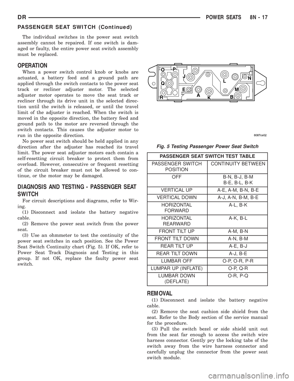
(3) Use an ohmmeter to test the continuity of the
power seat switches in each position. See the Power
Seat Switch Continuity chart (Fig. 5). If OK, refer to
Power Seat Track Diagnosis and Testing in this
group. If not OK, replace the faulty power seat
switch.
PASSENGER SEAT SWITCH TEST TABLE
PASSENGER SWITCH
POSITIONCONTINUITY BETWEEN
OFF B-N, B-J, B-M
B-E, B-L, B-K
VERTICAL UP A-E, A-M, B-N, B-E
VERTICAL DOWN A-J, A-N, B-M, B-E
HORIZONTAL
FORWARDA-L, B-K
HORIZONTAL
REARWARDA-K, B-L
FRONT TILT UP A-M, B-N
FRONT TILT DOWN A-N, B-M
REAR TILT UP A-E, B-J
REAR TILT DOWN A-J, B-E
LUMBAR OFF O-P, O-R, P-R
LUMPAR UP (INFLATE) O-P, Q-R
LUMBAR DOWN
(DEFLATE)O-R, P-Q
REMOVAL
(1) Disconnect and isolate the battery negative
cable.
(2) Remove the seat cushion side shield from the
seat. Refer to the Body section of the service manual
for the procedure.
(3) Pull the switch bezel or side shield unit out
from the seat far enough to access the switch wire
harness connector. Gently pry the locking tabs of the
switch away from the wire harness connector and
carefully unplug the connector from the power seat
switch module.
Fig. 5 Testing Passenger Power Seat Switch
DRPOWER SEATS 8N - 17
PASSENGER SEAT SWITCH (Continued)
Page 608 of 2895
ment in the event of an accidental deployment. When
handling a non-deployed seat belt tensioner, take
proper care to keep fingers out from under the
retractor cover and away from the seat belt webbing
where it exits from the retractor cover. In addition,
the supplemental restraint system should be dis-
armed whenever any steering wheel, steering col-
umn, seat belt tensioner, driver airbag, passenger
airbag, side curtain airbag, or instrument panel com-
ponents require diagnosis or service. Failure to
observe this warning could result in accidental air-
bag deployment and possible personal injury.
All damaged, faulty or non-deployed airbags and
seat belt tensioners which are replaced on vehicles
are to be handled and disposed of properly. If an air-
bag or seat belt tensioner unit is faulty or damaged
and non-deployed, refer to the Hazardous Substance
Control System for proper disposal. Dispose of all
non-deployed and deployed airbags and seat belt ten-
sioners in a manner consistent with state, provincial,
local and federal regulations.
SUPPLEMENTAL RESTRAINT STORAGE
Airbags and seat belt tensioners must be stored in
their original, special container until they are used
for service. Also, they must be stored in a clean, dry
environment; away from sources of extreme heat,
sparks, and high electrical energy. Always place or
store any airbag on a surface with its trim cover or
airbag cushion side facing up, to minimize movement
in case of an accidental deployment.
STANDARD PROCEDURE - SERVICE AFTER A
SUPPLEMENTAL RESTRAINT DEPLOYMENT
Any vehicle which is to be returned to use follow-
ing a supplemental restraint deployment, must have
the deployed restraints replaced. In addition, if the
driver airbag has been deployed, the clockspring
must be replaced. If the passenger airbag is
deployed, the passenger airbag door must be
replaced. The seat belt tensioners are deployed by
the same signal that deploys the driver and passen-
ger airbags and must also be replaced if either front
airbag has been deployed. If a side curtain airbag
has been deployed, the complete airbag unit, the
headliner, as well as the upper A, B, and C-pillar
trim must be replaced. These components are not
intended for reuse and will be damaged or weakened
as a result of a supplemental restraint deployment,
which may or may not be obvious during a visual
inspection.
It is also critical that the mounting surfaces and/or
mounting brackets for the Airbag Control Module
(ACM) and Side Impact Airbag Control Module
(SIACM) be closely inspected and restored to their
original conditions following any vehicle impact dam-age. Because the ACM and SIACM each contain
impact sensors that are used by the supplemental
restraint system to monitor or confirm the direction
and severity of a vehicle impact, improper orientation
or insecure fastening of these components may cause
airbags not to deploy when required, or to deploy
when not required. All other vehicle components
should be closely inspected following any supplemen-
tal restraint deployment, but are to be replaced only
as required by the extent of the visible damage
incurred.
CLEANUP PROCEDURE
Following a supplemental restraint deployment,
the vehicle interior will contain a powdery residue.
This residue consists primarily of harmless particu-
late by-products of the small pyrotechnic charge that
initiates the propellant used to deploy a supplemen-
tal restraint. However, this residue may also contain
traces of sodium hydroxide powder, a chemical
by-product of the propellant material that is used to
generate the inert gas that inflates the airbag. Since
sodium hydroxide powder can irritate the skin, eyes,
nose, or throat, be certain to wear safety glasses,
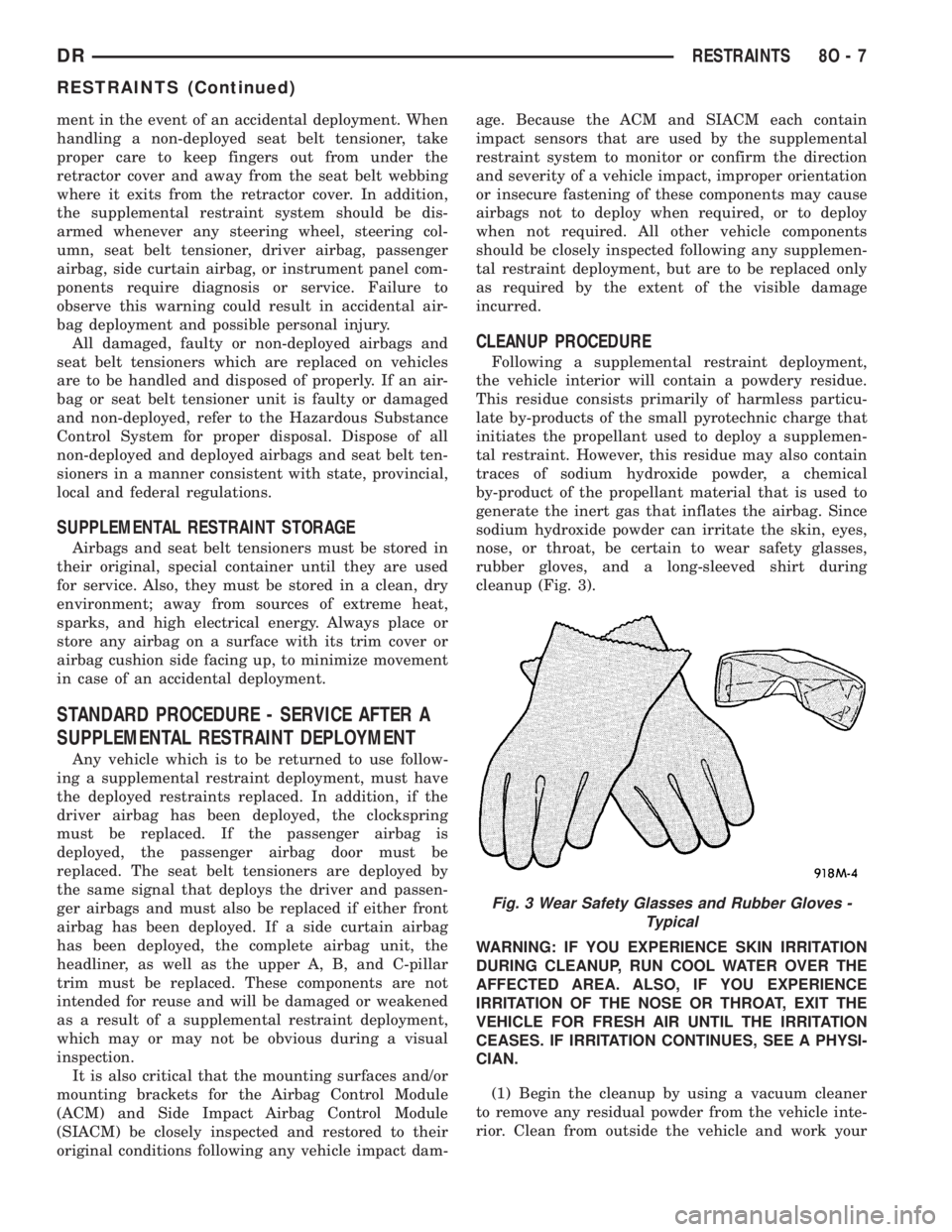
rubber gloves, and a long-sleeved shirt during
cleanup (Fig. 3).
WARNING: IF YOU EXPERIENCE SKIN IRRITATION
DURING CLEANUP, RUN COOL WATER OVER THE
AFFECTED AREA. ALSO, IF YOU EXPERIENCE
IRRITATION OF THE NOSE OR THROAT, EXIT THE
VEHICLE FOR FRESH AIR UNTIL THE IRRITATION
CEASES. IF IRRITATION CONTINUES, SEE A PHYSI-
CIAN.
(1) Begin the cleanup by using a vacuum cleaner
to remove any residual powder from the vehicle inte-
rior. Clean from outside the vehicle and work your
Fig. 3 Wear Safety Glasses and Rubber Gloves -
Typical
DRRESTRAINTS 8O - 7
RESTRAINTS (Continued)
Page 1263 of 2895
DESCRIPTION SPECIFICATION
Length (Overall)
Intake 113.45 - 114.21 mm
(4.4666 - 4.4965)
Exhaust 114.92 - 115.68 mm
(4.5244 - 4.5543 in.)
Stem Diameter
Intake 6.931 - 6.957 mm
(0.2729 - 0.2739 in.)
Exhaust 6.902 - 6.928 mm
(0.2717 - 0.2728 in.)
Stem - to - Guide
Clearance
Intake 0.018 - 0.069 mm
(0.0008 - 0.0028 in.)
Exhaust 0.047 - 0.098 mm
(0.0019 - 0.0039 in.)
Max. Allowable Stem -
to -
Guide Clearance
(Rocking
Method)
Intake 0.069 mm (0.0028 in.)
Exhaust 0.098 mm (0.0039 in.)
Valve Lift (Zero Lash)
Intake 12.00 mm (0.472 in.)
Exhaust 10.90 mm (0.4292 in.)
VALVE SPRING
Free Length (Approx)
Intake 48.92 mm (1.9260 in.)
Exhaust 49.81 mm (1.9610 in.)
Spring Force (Valve
Closed)
Intake 361.0 - 390.0 N @ 40.12
mm
(81.15 - 87.67 lbs. @
1.5795 in.)
Exhaust 390.0 - 430.0 N @ 40.12
mm
(87.67 - 96.66 lbs. @
1.5795 in.)DESCRIPTION SPECIFICATION
Spring Force (Valve
Open)
Intake 984.0 - 1040.0 N @
28.12 mm
221.2 - 233.8 lbs. @
1.107 in.)
Exhaust 965.0 - 1055.0 N @
28.12 mm
216.9 - 237.1 lbs. @
1.107 in.)
Number of Coils
Intake 7.30
Exhaust 7.45
Wire Diameter
Intake and Exhaust 4.77 ý 3.80mm
(0.1878 - 0.1496 in.)
Installed Height (Spring
Seat to Bottom of
Retainer)
Nominal
Intake 40.12 mm (1.579 in.)
Exhaust 40.12 mm (1.579 in.)
CYLINDER HEAD
Gasket Thickness
(Compressed) 0.7 mm (0.0276 in.)
Valve Seat Angle 44.5É - 45.0É
Valve Seat Runout (MAX) 0.051 mm (0.002 in.)
Valve Seat Width
Intake 1.75 - 2.36 mm
(0.0698 - 0.0928 in.)
Exhaust 1.71 - 2.32 mm
(0.0673 - 0.0911 in.)
Guide Bore Diameter
(Std.)6.975 - 7.00 mm
(0.2747 - 0.2756 in.)
Cylinder Head Warpage
(Flatness) 0.0508 mm (0.002 in.)
OIL PUMP
Clearance Over
Rotors/End Face (MAX)0.095 mm
(0.0038 in.)
9 - 14 ENGINE - 3.7LDR
ENGINE - 3.7L (Continued)
Page 1264 of 2895
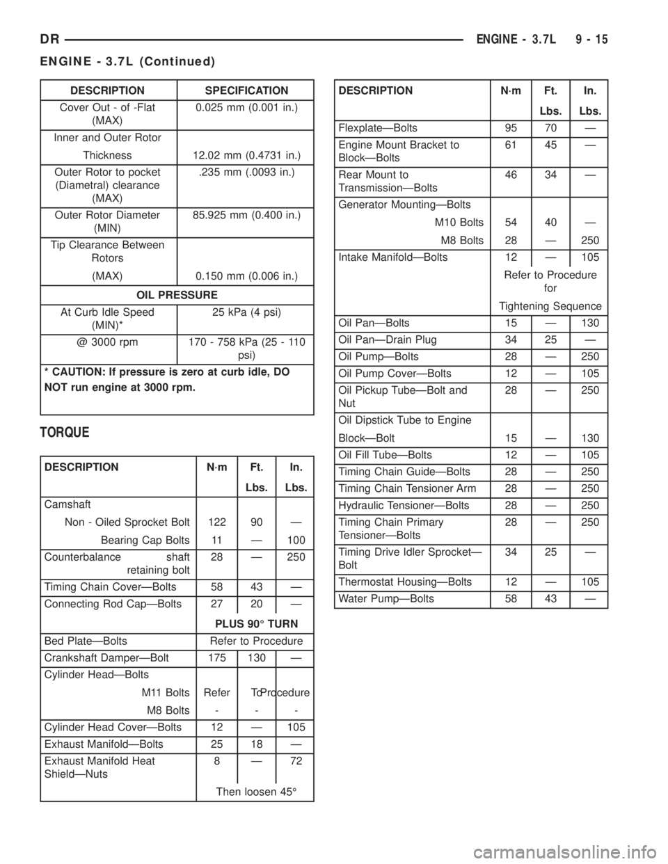
DESCRIPTION SPECIFICATION
Cover Out - of -Flat
(MAX)0.025 mm (0.001 in.)
Inner and Outer Rotor
Thickness 12.02 mm (0.4731 in.)
Outer Rotor to pocket
(Diametral) clearance
(MAX).235 mm (.0093 in.)
Outer Rotor Diameter
(MIN)85.925 mm (0.400 in.)
Tip Clearance Between
Rotors
(MAX) 0.150 mm (0.006 in.)
OIL PRESSURE
At Curb Idle Speed
(MIN)*25 kPa (4 psi)
@ 3000 rpm 170 - 758 kPa (25 - 110
psi)
* CAUTION: If pressure is zero at curb idle, DO
NOT run engine at 3000 rpm.
TORQUE
DESCRIPTION N´m Ft. In.
Lbs. Lbs.
Camshaft
Non - Oiled Sprocket Bolt 122 90 Ð
Bearing Cap Bolts 11 Ð 100
Counterbalance shaft
retaining bolt28 Ð 250
Timing Chain CoverÐBolts 58 43 Ð
Connecting Rod CapÐBolts 27 20 Ð
PLUS 90É TURN
Bed PlateÐBolts Refer to Procedure
Crankshaft DamperÐBolt 175 130 Ð
Cylinder HeadÐBolts
M11 Bolts Refer ToProcedure
M8 Bolts - - -
Cylinder Head CoverÐBolts 12 Ð 105
Exhaust ManifoldÐBolts 25 18 Ð
Exhaust Manifold Heat
ShieldÐNuts8Ð72
Then loosen 45É
DESCRIPTION N´m Ft. In.
Lbs. Lbs.
FlexplateÐBolts 95 70 Ð
Engine Mount Bracket to
BlockÐBolts61 45 Ð
Rear Mount to
TransmissionÐBolts46 34 Ð
Generator MountingÐBolts
M10 Bolts 54 40 Ð
M8 Bolts 28 Ð 250
Intake ManifoldÐBolts 12 Ð 105
Refer to Procedure
for
Tightening Sequence
Oil PanÐBolts 15 Ð 130
Oil PanÐDrain Plug 34 25 Ð
Oil PumpÐBolts 28 Ð 250
Oil Pump CoverÐBolts 12 Ð 105
Oil Pickup TubeÐBolt and
Nut28 Ð 250
Oil Dipstick Tube to Engine
BlockÐBolt 15 Ð 130
Oil Fill TubeÐBolts 12 Ð 105
Timing Chain GuideÐBolts 28 Ð 250
Timing Chain Tensioner Arm 28 Ð 250
Hydraulic TensionerÐBolts 28 Ð 250
Timing Chain Primary
TensionerÐBolts28 Ð 250
Timing Drive Idler SprocketÐ
Bolt34 25 Ð
Thermostat HousingÐBolts 12 Ð 105
Water PumpÐBolts 58 43 Ð
DRENGINE - 3.7L 9 - 15
ENGINE - 3.7L (Continued)
Page 1349 of 2895
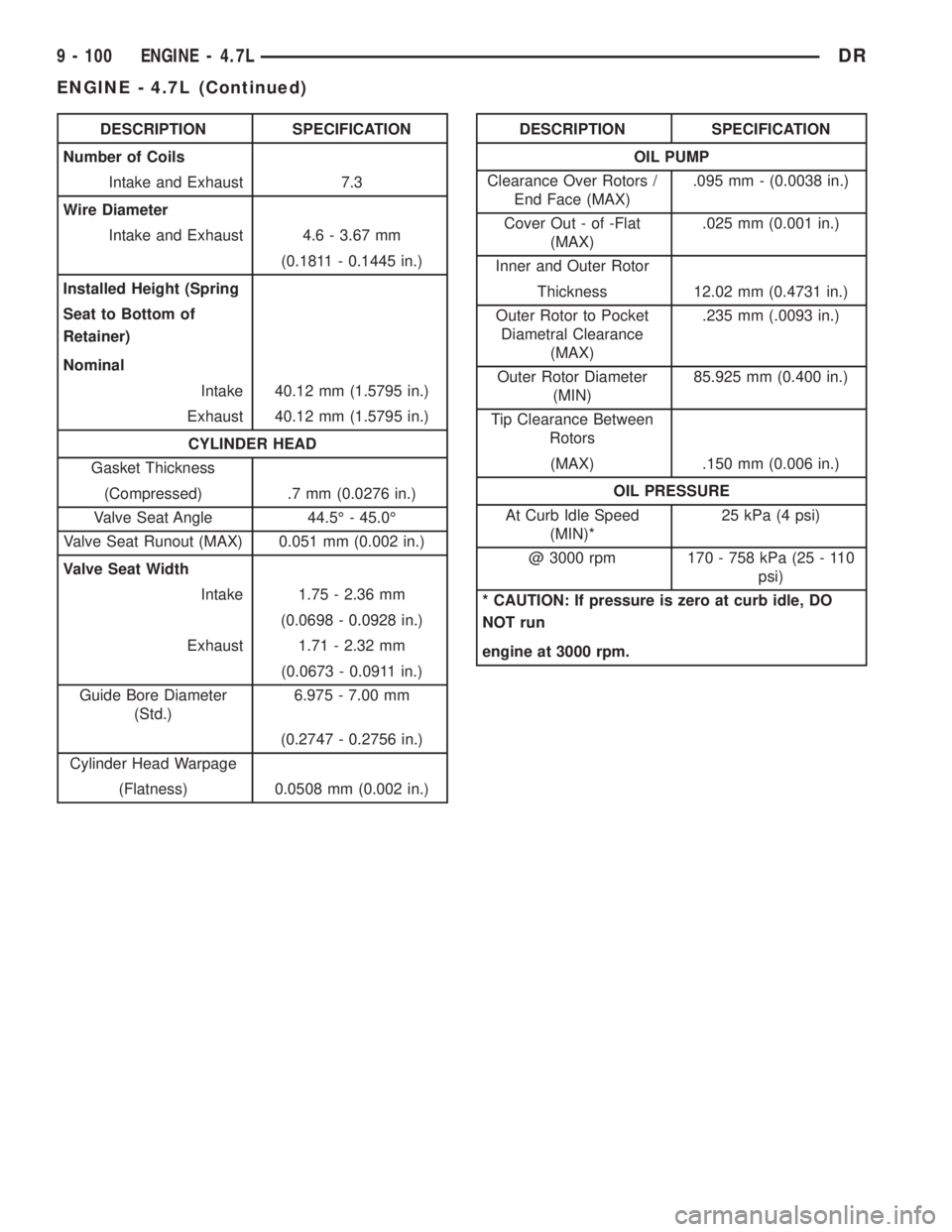
DESCRIPTION SPECIFICATION
Number of Coils
Intake and Exhaust 7.3
Wire Diameter
Intake and Exhaust 4.6 - 3.67 mm
(0.1811 - 0.1445 in.)
Installed Height (Spring
Seat to Bottom of
Retainer)
Nominal
Intake 40.12 mm (1.5795 in.)
Exhaust 40.12 mm (1.5795 in.)
CYLINDER HEAD
Gasket Thickness
(Compressed) .7 mm (0.0276 in.)
Valve Seat Angle 44.5É - 45.0É
Valve Seat Runout (MAX) 0.051 mm (0.002 in.)
Valve Seat Width
Intake 1.75 - 2.36 mm
(0.0698 - 0.0928 in.)
Exhaust 1.71 - 2.32 mm
(0.0673 - 0.0911 in.)
Guide Bore Diameter
(Std.)6.975 - 7.00 mm
(0.2747 - 0.2756 in.)
Cylinder Head Warpage
(Flatness) 0.0508 mm (0.002 in.)DESCRIPTION SPECIFICATION
OIL PUMP
Clearance Over Rotors /
End Face (MAX).095 mm - (0.0038 in.)
Cover Out - of -Flat
(MAX).025 mm (0.001 in.)
Inner and Outer Rotor
Thickness 12.02 mm (0.4731 in.)
Outer Rotor to Pocket
Diametral Clearance
(MAX).235 mm (.0093 in.)
Outer Rotor Diameter
(MIN)85.925 mm (0.400 in.)
Tip Clearance Between
Rotors
(MAX) .150 mm (0.006 in.)
OIL PRESSURE
At Curb Idle Speed
(MIN)*25 kPa (4 psi)
@ 3000 rpm 170 - 758 kPa (25 - 110
psi)
* CAUTION: If pressure is zero at curb idle, DO
NOT run
engine at 3000 rpm.
9 - 100 ENGINE - 4.7LDR
ENGINE - 4.7L (Continued)
Page 1486 of 2895
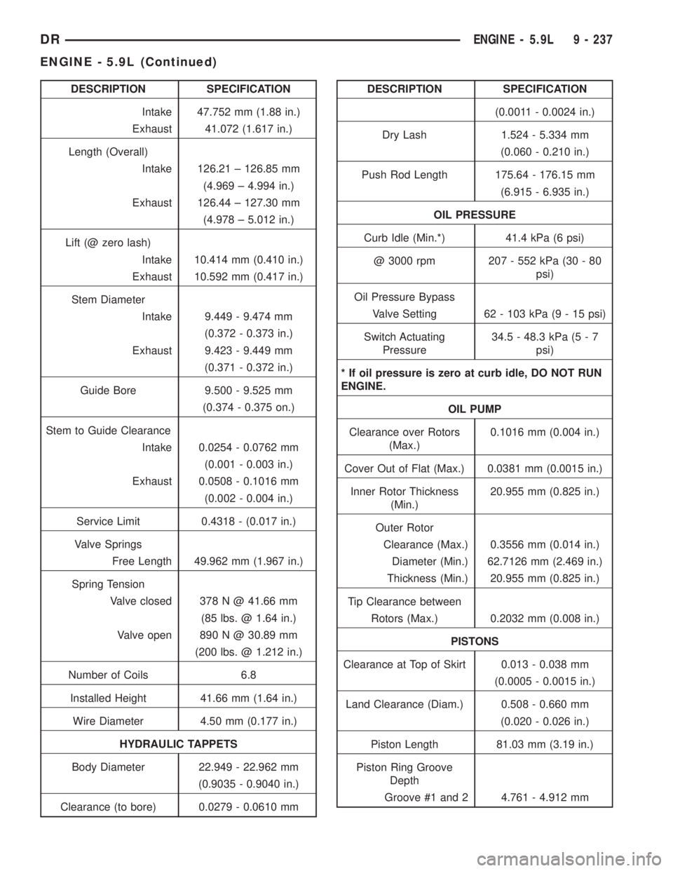
DESCRIPTION SPECIFICATION
Intake 47.752 mm (1.88 in.)
Exhaust 41.072 (1.617 in.)
Length (Overall)
Intake 126.21 ± 126.85 mm
(4.969 ± 4.994 in.)
Exhaust 126.44 ± 127.30 mm
(4.978 ± 5.012 in.)
Lift (@ zero lash)
Intake 10.414 mm (0.410 in.)
Exhaust 10.592 mm (0.417 in.)
Stem Diameter
Intake 9.449 - 9.474 mm
(0.372 - 0.373 in.)
Exhaust 9.423 - 9.449 mm
(0.371 - 0.372 in.)
Guide Bore 9.500 - 9.525 mm
(0.374 - 0.375 on.)
Stem to Guide Clearance
Intake 0.0254 - 0.0762 mm
(0.001 - 0.003 in.)
Exhaust 0.0508 - 0.1016 mm
(0.002 - 0.004 in.)
Service Limit 0.4318 - (0.017 in.)
Valve Springs
Free Length 49.962 mm (1.967 in.)
Spring Tension
Valve closed 378 N @ 41.66 mm
(85 lbs. @ 1.64 in.)
Valve open 890 N @ 30.89 mm
(200 lbs. @ 1.212 in.)
Number of Coils 6.8
Installed Height 41.66 mm (1.64 in.)
Wire Diameter 4.50 mm (0.177 in.)
HYDRAULIC TAPPETS
Body Diameter 22.949 - 22.962 mm
(0.9035 - 0.9040 in.)
Clearance (to bore) 0.0279 - 0.0610 mmDESCRIPTION SPECIFICATION
(0.0011 - 0.0024 in.)
Dry Lash 1.524 - 5.334 mm
(0.060 - 0.210 in.)
Push Rod Length 175.64 - 176.15 mm
(6.915 - 6.935 in.)
OIL PRESSURE
Curb Idle (Min.*) 41.4 kPa (6 psi)
@ 3000 rpm 207 - 552 kPa (30 - 80
psi)
Oil Pressure Bypass
Valve Setting 62 - 103 kPa (9 - 15 psi)
Switch Actuating
Pressure34.5 - 48.3 kPa (5 - 7
psi)
* If oil pressure is zero at curb idle, DO NOT RUN
ENGINE.
OIL PUMP
Clearance over Rotors
(Max.)0.1016 mm (0.004 in.)
Cover Out of Flat (Max.) 0.0381 mm (0.0015 in.)
Inner Rotor Thickness
(Min.)20.955 mm (0.825 in.)
Outer Rotor
Clearance (Max.) 0.3556 mm (0.014 in.)
Diameter (Min.) 62.7126 mm (2.469 in.)
Thickness (Min.) 20.955 mm (0.825 in.)
Tip Clearance between
Rotors (Max.) 0.2032 mm (0.008 in.)
PISTONS
Clearance at Top of Skirt 0.013 - 0.038 mm
(0.0005 - 0.0015 in.)
Land Clearance (Diam.) 0.508 - 0.660 mm
(0.020 - 0.026 in.)
Piston Length 81.03 mm (3.19 in.)
Piston Ring Groove
Depth
Groove #1 and 2 4.761 - 4.912 mm
DRENGINE - 5.9L 9 - 237
ENGINE - 5.9L (Continued)
Page 1615 of 2895
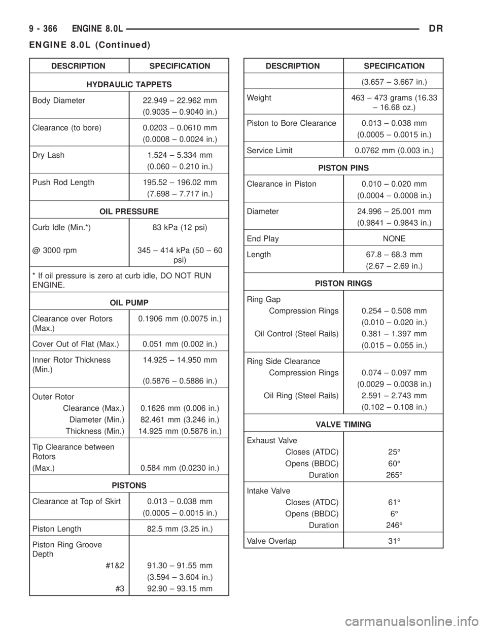
DESCRIPTION SPECIFICATION
HYDRAULIC TAPPETS
Body Diameter 22.949 ± 22.962 mm
(0.9035 ± 0.9040 in.)
Clearance (to bore) 0.0203 ± 0.0610 mm
(0.0008 ± 0.0024 in.)
Dry Lash 1.524 ± 5.334 mm
(0.060 ± 0.210 in.)
Push Rod Length 195.52 ± 196.02 mm
(7.698 ± 7.717 in.)
OIL PRESSURE
Curb Idle (Min.*) 83 kPa (12 psi)
@ 3000 rpm 345 ± 414 kPa (50 ± 60
psi)
* If oil pressure is zero at curb idle, DO NOT RUN
ENGINE.
OIL PUMP
Clearance over Rotors
(Max.)0.1906 mm (0.0075 in.)
Cover Out of Flat (Max.) 0.051 mm (0.002 in.)
Inner Rotor Thickness
(Min.)14.925 ± 14.950 mm
(0.5876 ± 0.5886 in.)
Outer Rotor
Clearance (Max.) 0.1626 mm (0.006 in.)
Diameter (Min.) 82.461 mm (3.246 in.)
Thickness (Min.) 14.925 mm (0.5876 in.)
Tip Clearance between
Rotors
(Max.) 0.584 mm (0.0230 in.)
PISTONS
Clearance at Top of Skirt 0.013 ± 0.038 mm
(0.0005 ± 0.0015 in.)
Piston Length 82.5 mm (3.25 in.)
Piston Ring Groove
Depth
#1&2 91.30 ± 91.55 mm
(3.594 ± 3.604 in.)
#3 92.90 ± 93.15 mmDESCRIPTION SPECIFICATION
(3.657 ± 3.667 in.)
Weight 463 ± 473 grams (16.33
± 16.68 oz.)
Piston to Bore Clearance 0.013 ± 0.038 mm
(0.0005 ± 0.0015 in.)
Service Limit 0.0762 mm (0.003 in.)
PISTON PINS
Clearance in Piston 0.010 ± 0.020 mm
(0.0004 ± 0.0008 in.)
Diameter 24.996 ± 25.001 mm
(0.9841 ± 0.9843 in.)
End Play NONE
Length 67.8 ± 68.3 mm
(2.67 ± 2.69 in.)
PISTON RINGS
Ring Gap
Compression Rings 0.254 ± 0.508 mm
(0.010 ± 0.020 in.)
Oil Control (Steel Rails) 0.381 ± 1.397 mm
(0.015 ± 0.055 in.)
Ring Side Clearance
Compression Rings 0.074 ± 0.097 mm
(0.0029 ± 0.0038 in.)
Oil Ring (Steel Rails) 2.591 ± 2.743 mm
(0.102 ± 0.108 in.)
VALVE TIMING
Exhaust Valve
Closes (ATDC) 25É
Opens (BBDC) 60É
Duration 265É
Intake Valve
Closes (ATDC) 61É
Opens (BBDC) 6É
Duration 246É
Valve Overlap 31É
9 - 366 ENGINE 8.0LDR
ENGINE 8.0L (Continued)
Page 2343 of 2895
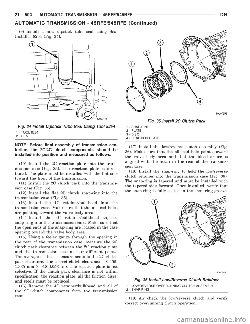
(9) Install a new dipstick tube seal using Seal
Installer 8254 (Fig. 34).
NOTE: Before final assembly of transmission cen-
terline, the 2C/4C clutch components should be
installed into position and measured as follows:
(10) Install the 2C reaction plate into the trans-
mission case (Fig. 35). The reaction plate is direc-
tional. The plate must be installed with the flat side
toward the front of the transmission.
(11) Install the 2C clutch pack into the transmis-
sion case (Fig. 35).
(12) Install the flat 2C clutch snap-ring into the
transmission case (Fig. 35).
(13) Install the 4C retainer/bulkhead into the
transmission case. Make sure that the oil feed holes
are pointing toward the valve body area.
(14) Install the 4C retainer/bulkhead tapered
snap-ring into the transmission case. Make sure that
the open ends of the snap-ring are located in the case
opening toward the valve body area.
(15) Using a feeler gauge through the opening in
the rear of the transmission case, measure the 2C
clutch pack clearance between the 2C reaction plate
and the transmission case at four different points.
The average of these measurements is the 2C clutch
pack clearance. The correct clutch clearance is 0.455-
1.335 mm (0.018-0.053 in.). The reaction plate is not
selective. If the clutch pack clearance is not within
specification, the reaction plate, all the friction discs,
and steels must be replaced.
(16) Remove the 4C retainer/bulkhead and all of
the 2C clutch components from the transmission
case.(17) Install the low/reverse clutch assembly (Fig.
36). Make sure that the oil feed hole points toward
the valve body area and that the bleed orifice is
aligned with the notch in the rear of the transmis-
sion case.
(18) Install the snap-ring to hold the low/reverse
clutch retainer into the transmission case (Fig. 36).
The snap-ring is tapered and must be installed with
the tapered side forward. Once installed, verify that
the snap-ring is fully seated in the snap-ring groove.
(19) Air check the low/reverse clutch and verify
correct overrunning clutch operation.
Fig. 34 Install Dipstick Tube Seal Using Tool 8254
1 - TOOL 8254
2 - SEAL
Fig. 35 Install 2C Clutch Pack
1 - SNAP-RING
2 - PLATE
3 - DISC
4 - REACTION PLATE
Fig. 36 Install Low/Reverse Clutch Retainer
1 - LOW/REVERSE OVERRUNNING CLUTCH ASSEMBLY
2 - SNAP-RING
21 - 504 AUTOMATIC TRANSMISSION - 45RFE/545RFEDR
AUTOMATIC TRANSMISSION - 45RFE/545RFE (Continued)
Page 2399 of 2895
INSTALLATION
(1) Install the line pressure sensor into the trans-
mission case.
(2) Install the bolt to hold the line pressure sensor
into the transmission case. Tighten the bolt to 11.9
N´m (105 in.lbs.).
(3) Install the wiring connector onto the line pres-
sure sensor
(4) Verify the transmission fluid level. Add fluid as
necessary.
(5) Lower vehicle.
LOW/REVERSE CLUTCH
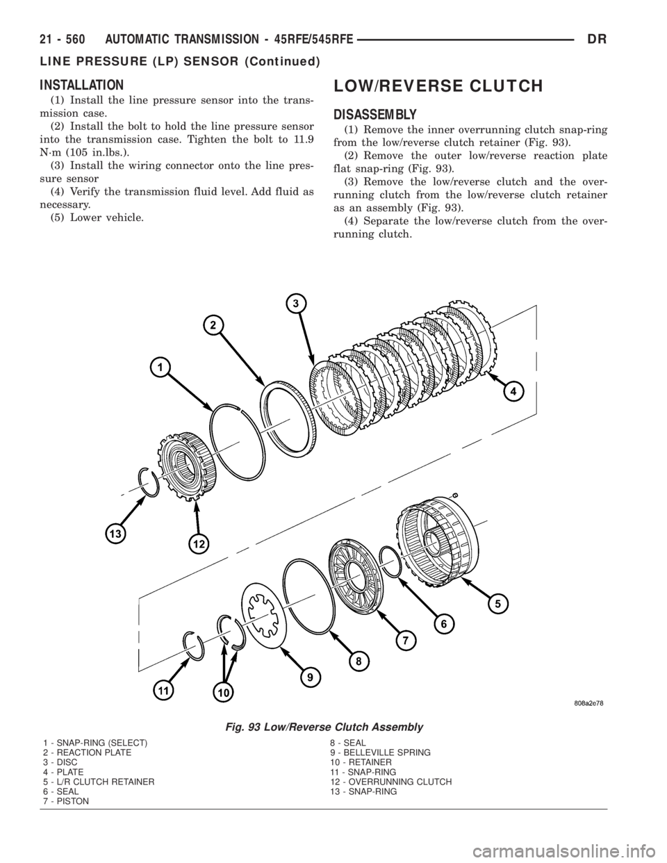
DISASSEMBLY
(1) Remove the inner overrunning clutch snap-ring
from the low/reverse clutch retainer (Fig. 93).
(2) Remove the outer low/reverse reaction plate
flat snap-ring (Fig. 93).
(3) Remove the low/reverse clutch and the over-
running clutch from the low/reverse clutch retainer
as an assembly (Fig. 93).
(4) Separate the low/reverse clutch from the over-
running clutch.
Fig. 93 Low/Reverse Clutch Assembly
1 - SNAP-RING (SELECT) 8 - SEAL
2 - REACTION PLATE 9 - BELLEVILLE SPRING
3 - DISC 10 - RETAINER
4 - PLATE 11 - SNAP-RING
5 - L/R CLUTCH RETAINER 12 - OVERRUNNING CLUTCH
6 - SEAL 13 - SNAP-RING
7 - PISTON
21 - 560 AUTOMATIC TRANSMISSION - 45RFE/545RFEDR
LINE PRESSURE (LP) SENSOR (Continued)