warning lights DODGE RAM 2003 Service Repair Manual
[x] Cancel search | Manufacturer: DODGE, Model Year: 2003, Model line: RAM, Model: DODGE RAM 2003Pages: 2895, PDF Size: 83.15 MB
Page 539 of 2895
MULTI-FUNCTION SWITCH
DESCRIPTION - TURN SIGNAL SYSTEM.....17
OPERATION - TURN SIGNAL SYSTEM.......18
DIAGNOSIS AND TESTING - MULTI-
FUNCTION SWITCH...................18
REMOVAL.............................18
INSTALLATION.........................19
PARK LAMP RELAY
DESCRIPTION.........................19
OPERATION...........................19
DIAGNOSIS AND TESTING - PARK LAMP
RELAY..............................20
REMOVAL.............................20
INSTALLATION.........................21
PARK/TURN SIGNAL LAMP
REMOVAL.............................21
INSTALLATION.........................21TAIL LAMP
REMOVAL.............................21
INSTALLATION.........................21
TAIL LAMP UNIT
REMOVAL.............................21
INSTALLATION.........................21
TRAILER TOW WIRING
DESCRIPTION.........................22
TURN LAMP
REMOVAL.............................22
INSTALLATION.........................22
UNDERHOOD LAMP
REMOVAL.............................22
INSTALLATION.........................22
UNDERHOOD LAMP UNIT
REMOVAL.............................22
INSTALLATION.........................23
LAMPS/LIGHTING - EXTERIOR
DESCRIPTION
The exterior lighting system for this model include
the following components:
²Backup Lamps
²Brake Lamps
²Daytime Running Lamps
²Front Fog Lamps
²Hazard Warning Lamps
²Headlamps
²Park Lamps
²Turn Signal Lamps
Other components of the exterior lighting system
for this model include:
²Backup Lamp Switch
²Brake Lamp Switch
²Front Control Module
²Front Fog Lamp Relay
²Hazard Switch
²Multi-Function Switch
²Park Lamp Relay
²Trailer Tow Connectors
Some of the interior and exterior lighting functions
are governed by the front control module. The head-
lamp, dome, and door ajar switchs provide signals to
the instrument cluster. The instrument cluster sends
a J1850 message to the front control module to
enable the necessary components for illumination.
Hard wired circuitry connects the exterior lighting
system components to the electrical system of the
vehicle. Refer to the appropriate wiring information.
OPERATION
DAYTIME RUNNING LAMPS
Power is reduced using pulse-width modulation to
the high beams, where by the power is switched on
and off rapidly instead of remaining on continuously.
The duration and interval of the power pulses is pro-
grammed into the Front Control Module (FCM).
HEADLAMP SYSTEM
The instrument cluster monitors both the multi-
plexed headlamp and multifunction switches. The
instrument cluster transmits a J1850 bus message to
the front control module (FCM) to activate the head-
lamps. The headlamp system will default to head-
lamps ON position when ignition switch is ON and
when an open or short circuit failure occurs on the
headlamp switch input to the instrument cluster. The
system will return to normal operation when the
open or short is repaired. A fault will be reported by
the Instrument Cluster when a failure occurs on the
dimmer or headlamp switch input.
If the exterior lamps are ON, and the headlamp
switch is in any position other than OFF, with the
ignition switch OFF (LOCK) after 5 minutes, the
Instrument Cluster transmits a message via J1850
informing the the FCM. The FCM will then turn off
the headlamps, park lamps and fog lamps. This fea-
ture (load shed) prevents the vehicle battery from
being discharged when the vehicle lights have been
left ON.
HEADLAMP TIME DELAY SYSTEM
The headlamp time delay system is activated by
turning the headlamps ON (high or low beam) while
the engine is running, turning the ignition switch
OFF, and then turning the headlamp switch OFF
8L - 2 LAMPS/LIGHTING - EXTERIORDR
Page 572 of 2895
(2) Momentarily depress and release the Menu
push button to step through the programmable fea-
tures list. Each programmable feature and its cur-
rently selected option will appear on the EVIC
display in the sequence shown in the Programmable
Features list that follows.
(3) Momentarily depress and release the Step push
button to step through the available options for the
programmable feature being displayed.
(4) The option that last appears in the display
with a programmable feature before exiting the pro-
gramming mode, becomes the newly selected pro-
grammable feature option.
(5) The EVIC exits the programming mode and
returns to its normal operating mode when the C/T
push button is depressed or when the end of the pro-
grammable features menu list is reached, whichever
occurs first.
PROGRAMMABLE FEATURES
²LANGUAGE?- The options include English,
Francaise, Deutsch, Italiana, or Espanol. The default
is English. All EVIC display nomenclature, including
the trip computer functions, warning messages and
the programmable features appear in the selected
language.
²DISPLAY U.S. OR METRIC?- The options
include U.S. and M. The default is U.S. This feature
toggles the trip computer temperature, fuel economy
and odometer display readings between U.S. and
metric units of measure.
²SERVICE INTV. =- The options include from
3200 to 12000 kilometers in 800 kilometer incre-
ments (2000 to 6000 miles in 500 mile increments).
The default is 12000 kilometers (6000 miles). The
selected distance becomes the interval at which the
Perform Service warning message will be displayed
by the EVIC. If a new distance is selected, a second
programmable feature appears,RESET SERVICE
DISTANCE?- The options include No and Yes. The
default is Yes. When Yes is selected, the accumulated
distance since the last previous Perform Service
warning message will be reset to zero because the
service interval has been changed. When No is
selected, the distance until the next Perform Service
warning message is reduced by the accumulated dis-
tance since the last previous message.
²AUTO DOOR LOCKS?- The options include
Yes and No. The default is Yes. When Yes is selected,
all doors lock automatically when vehicle speed
reaches 25 kilometers-per-hour (15 miles-per-hour). If
YES is selected, a second programmable feature
appears,AUTO UNLOCK ON EXIT?- The options
again include Yes and No. The default is No. When
Yes is selected, following each Auto Door Lock event
all doors will automatically unlock when the driverdoor is opened, if the vehicle is stopped and the
transmission gear selector is in Park or Neutral. The
Auto Door Unlock event will only occur once follow-
ing each Auto Door Lock event.
²REMOTE UNLOCK- The options include
Driver Door 1st and All Doors. The default is Driver
Door 1st. When Diver Door 1st is selected, only the
driver door unlocks when the Unlock button of the
Remote Keyless Entry (RKE) transmitter is
depressed once. The Unlock button of the RKE trans-
mitter must be depressed twice to unlock all doors.
When All Doors is selected, all doors unlock when the
Unlock button of the RKE transmitter is depressed
once.
²SOUND HORN ON LOCK?- The options
include On and Off. The default is No. When Yes is
selected, a short horn chirp will provide an audible
confirmation when the RKE receiver recognizes a
valid Lock signal from an RKE transmitter. When No
is selected, no horn chirp will occur with the RKE
Lock event. This feature may be selected indepen-
dent of theFLASH LIGHTS WITH LOCKS?pro-
grammable feature.
²FLASH LIGHTS WITH LOCKS?- The options
include Yes and No. The default is Yes. When Yes is
selected, a single flash of the hazard warning lamps
will provide an optical confirmation when the RKE
receiver recognizes a valid Lock signal from an RKE
transmitter, and two flashes of the same lamps will
occur when the RKE receiver recognizes a valid
Unlock signal from an RKE transmitter. When No is
selected, no lamp flash will occur with the RKE Lock
or Unlock event. This feature may be selected inde-
pendent of theSOUND HORN ON LOCK?pro-
grammable feature.
²HEADLAMP DELAY =- The options include
Off, 30 Sec, 60 Sec, and 90 Sec. The default is 90 Sec.
When a time interval is selected, the headlamps will
remain on for that length of time when the head-
lamps are turned off after the ignition is turned off,
or if the Auto mode is selected on vehicles with the
Auto Headlamps option. When Off is selected, the
headlamp delay feature is disabled.
²TRAIN REMOTE- When this feature is
selected the driver can choose to train up to four
remote keyless entry transmitters. The options
include Yes and No. The default is No. When Yes is
selected and the MENU button is pressed the EVIC
will display ªPRESS REMOTE LOCK & UNLOCK
THEN PRESS UNLOCKº, followed by a chime to
indicate the training sequence can commence. You
have approximately 30 seconds to train up to four
transmitters, after each transmitter is trained a
chime will sound indicating that the training was
successful. If remote link to memory is ªYESº , the
first transmitter trained will be associated with
DRMESSAGE SYSTEMS 8M - 9
ELECTRONIC VEHICLE INFO CENTER (Continued)
Page 610 of 2895
If the stored DTC information is successfully erased,
go to Step 9.
(9) Turn the ignition switch to the Off position for
about fifteen seconds, and then back to the On posi-
tion. Observe the airbag indicator in the instrument
cluster. It should illuminate for six to eight seconds,
and then go out. This indicates that the supplemen-
tal restraint system is functioning normally and that
the repairs are complete. If the airbag indicator fails
to light, or lights and stays on, there is still an active
supplemental restraint system fault or malfunction.
Refer to the appropriate diagnostic information to
diagnose the problem.
ACM COVER
REMOVAL
The Airbag Control Module (ACM) cover is used
only on models with an automatic transmission. Mod-
els with a manual transmission require that the floor
console be removed to access the ACM for service.
(Refer to 23 - BODY/INTERIOR/FLOOR CONSOLE -
REMOVAL).
WARNING: ON VEHICLES EQUIPPED WITH AIR-
BAGS, DISABLE THE SUPPLEMENTAL RESTRAINT
SYSTEM BEFORE ATTEMPTING ANY STEERING
WHEEL, STEERING COLUMN, DRIVER AIRBAG,
PASSENGER AIRBAG, SEAT BELT TENSIONER,
SIDE CURTAIN AIRBAG, OR INSTRUMENT PANEL
COMPONENT DIAGNOSIS OR SERVICE. DISCON-
NECT AND ISOLATE THE BATTERY NEGATIVE
(GROUND) CABLE, THEN WAIT TWO MINUTES FOR
THE SYSTEM CAPACITOR TO DISCHARGE BEFORE
PERFORMING FURTHER DIAGNOSIS OR SERVICE.
THIS IS THE ONLY SURE WAY TO DISABLE THE
SUPPLEMENTAL RESTRAINT SYSTEM. FAILURE TO
TAKE THE PROPER PRECAUTIONS COULD
RESULT IN ACCIDENTAL AIRBAG DEPLOYMENT
AND POSSIBLE PERSONAL INJURY.
(1) Disconnect and isolate the battery negative
cable. Wait two minutes for the system capacitor to
discharge before further service.
(2) Using a trim stick or another suitable wide
flat-bladed tool, gently pry each side of the ACM
cover away from the instrument panel at each side of
the center bracket on the floor panel transmission
tunnel far enough to disengage the two snap clip
retainers from the instrument panel receptacles (Fig.
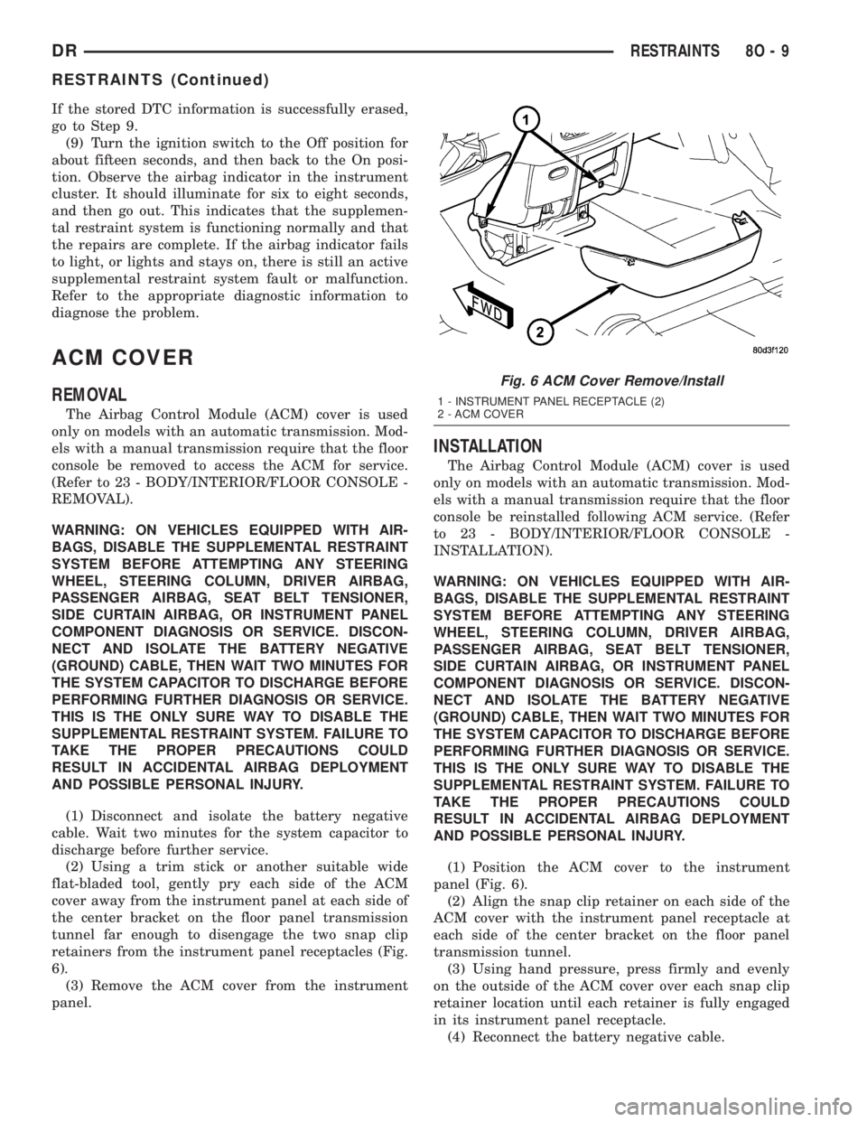
6).
(3) Remove the ACM cover from the instrument
panel.
INSTALLATION
The Airbag Control Module (ACM) cover is used
only on models with an automatic transmission. Mod-
els with a manual transmission require that the floor
console be reinstalled following ACM service. (Refer
to 23 - BODY/INTERIOR/FLOOR CONSOLE -
INSTALLATION).
WARNING: ON VEHICLES EQUIPPED WITH AIR-
BAGS, DISABLE THE SUPPLEMENTAL RESTRAINT
SYSTEM BEFORE ATTEMPTING ANY STEERING
WHEEL, STEERING COLUMN, DRIVER AIRBAG,
PASSENGER AIRBAG, SEAT BELT TENSIONER,
SIDE CURTAIN AIRBAG, OR INSTRUMENT PANEL
COMPONENT DIAGNOSIS OR SERVICE. DISCON-
NECT AND ISOLATE THE BATTERY NEGATIVE
(GROUND) CABLE, THEN WAIT TWO MINUTES FOR
THE SYSTEM CAPACITOR TO DISCHARGE BEFORE
PERFORMING FURTHER DIAGNOSIS OR SERVICE.
THIS IS THE ONLY SURE WAY TO DISABLE THE
SUPPLEMENTAL RESTRAINT SYSTEM. FAILURE TO
TAKE THE PROPER PRECAUTIONS COULD
RESULT IN ACCIDENTAL AIRBAG DEPLOYMENT
AND POSSIBLE PERSONAL INJURY.
(1) Position the ACM cover to the instrument
panel (Fig. 6).
(2) Align the snap clip retainer on each side of the
ACM cover with the instrument panel receptacle at
each side of the center bracket on the floor panel
transmission tunnel.
(3) Using hand pressure, press firmly and evenly
on the outside of the ACM cover over each snap clip
retainer location until each retainer is fully engaged
in its instrument panel receptacle.
(4) Reconnect the battery negative cable.
Fig. 6 ACM Cover Remove/Install
1 - INSTRUMENT PANEL RECEPTACLE (2)
2 - ACM COVER
DRRESTRAINTS 8O - 9
RESTRAINTS (Continued)
Page 1802 of 2895
INSTALLATION
WARNING: BEFORE SERVICING THE STEERING
COLUMN THE AIRBAG SYSTEM MUST BE DIS-
ARMED. REFER TO ELECTRICAL RESTRAINT SYS-
TEM FOR SERVICE PROCEDURES. FAILURE TO DO
SO MAY RESULT IN ACCIDENTAL DEPLOYMENT OF
THE AIRBAG AND POSSIBLE PERSONAL INJURY.
CAUTION: All fasteners must be torqued to specifi-
cation to ensure proper operation of the steering
column.
(1) Position the steering column on the dash panel
support and loosely install the mounting nuts.
(2) Firmly slide the steering column upward
against the studs in dash panel and hand tighten the
nuts.
(3) Install the steering shaft coupler on the steer-
ing shaft and loosely install anewbolt.
(4) Center steering column in dash opening and
tighten mounting nuts to 28 N´m (250 in. lbs.).
NOTE: Torque the upper left nut first then the lower
right nut. Then torque the lower left nut then the
upper right nut.
NOTE: A new bolt must be used for reinstallation.
(5) Tighten the coupler bolt to 57 N´m (42 ft. lbs.).
(6) Install a new brake light switch (Refer to 8 -
ELECTRICAL/LAMPS/LIGHTING - EXTERIOR/
BRAKE LAMP SWITCH - REMOVAL).(7) Install the shifter cable. (Refer to 21 - TRANS-
MISSION/TRANSAXLE/AUTOMATIC - 32RH/GEAR
SHIFT CABLE - INSTALLATION)
(8) Connect the wiring harness to the column.
(9) Install the SKIM module.
(10) Install the clockspring(Refer to 8 - ELECTRI-
CAL/RESTRAINTS/CLOCKSPRING - REMOVAL).
(11) Install the shrouds.
(12) Install the steering column opening cover
(Refer to 23 - BODY/INSTRUMENT PANEL/STEER-
ING COLUMN OPENING COVER - INSTALLA-
TION).
(13) Align the spline on the wheel hub to shaft.
(14) Then install the steering wheel and install a
newbolt. Tighten the bolt to 61 N´m (45 ft. lbs.).
(15) Install the airbag (Refer to 8 - ELECTRICAL/
RESTRAINTS/DRIVER AIRBAG - INSTALLATION).
(16) Install the two steering wheel switches.
(17) Install the tilt lever handle.
(18) Install the negative battery terminal.
(19) Test the operation of the horn, Electronic
PRNDL Indicator, lights and any other functions that
are steering column operated.IGNITION SWITCH
DESCRIPTION
The ignition switch is located on the steering col-
umn. It is used as the main on/off switching device
for most electrical components. The mechanical key
cylinder is used to engage/disengage the electrical
ignition switch.
OPERATION
Vehicles equipped with an automatic trans-
mission and a steering column mounted shifter:
an interlock device is located within the shift cable.
This interlock device is used to lock the transmission
shifter in the PARK position when the key cylinder is
in any position and the brake pedal is not depressed.
DIAGNOSIS AND TESTING - IGNITION SWITCH
TEST AND REPAIR
If the key removal effort is excessive on a vehicle
with a automatic transmission first adjust the shift
linkage, (Refer to 21 - TRANSMISSION/TRANS-
AXLE/AUTOMATIC - 46RE/GEAR SHIFT CABLE -
ADJUSTMENTS).
If the ignition switch effort is excessive remove the
ignition key cylinder from the steering column. (Refer
to 19 - STEERING/COLUMN/LOCK CYLINDER
HOUSING - REMOVAL). Check the turning effort of
the key cylinder. If the ignition key cylinder effort is
excessive replace the key cylinder.
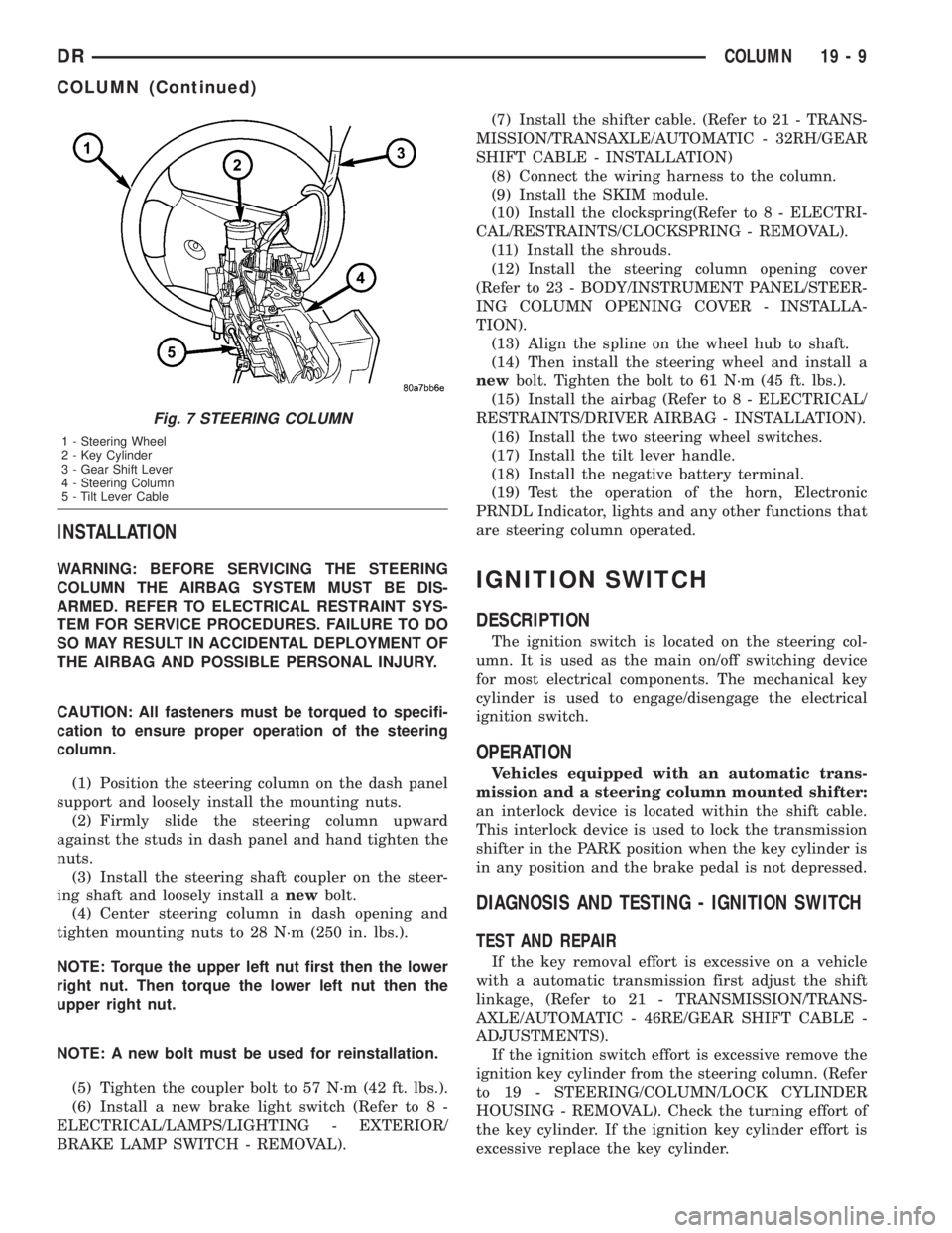
Fig. 7 STEERING COLUMN
1 - Steering Wheel
2 - Key Cylinder
3 - Gear Shift Lever
4 - Steering Column
5 - Tilt Lever Cable
DRCOLUMN 19 - 9
COLUMN (Continued)
Page 2577 of 2895
VISUAL INSPECTION BEFORE WATER LEAK TESTS
Verify that floor and body plugs are in place, body
drains are clear, and body components are properly
aligned and sealed. If component alignment or seal-
ing is necessary, refer to the appropriate section of
this group for proper procedures.
WATER LEAK TESTS
WARNING: DO NOT USE ELECTRIC SHOP LIGHTS
OR TOOLS IN WATER TEST AREA. PERSONAL
INJURY CAN RESULT.
When the conditions causing a water leak have
been determined, simulate the conditions as closely
as possible.
²If a leak occurs with the vehicle parked in a
steady light rain, flood the leak area with an open-
ended garden hose.
²If a leak occurs while driving at highway speeds
in a steady rain, test the leak area with a reasonable
velocity stream or fan spray of water. Direct the
spray in a direction comparable to actual conditions.
²If a leak occurs when the vehicle is parked on an
incline, hoist the end or side of the vehicle to simu-
late this condition. This method can be used when
the leak occurs when the vehicle accelerates, stops or
turns. If the leak occurs on acceleration, hoist the
front of the vehicle. If the leak occurs when braking,
hoist the back of the vehicle. If the leak occurs on left
turns, hoist the left side of the vehicle. If the leak
occurs on right turns, hoist the right side of the vehi-
cle. For hoisting recommendations (Refer to LUBRI-
CATION & MAINTENANCE/HOISTING -
STANDARD PROCEDURE).
WATER LEAK DETECTION
To detect a water leak point-of-entry, do a water
test and watch for water tracks or droplets forming
on the inside of the vehicle. If necessary, remove inte-
rior trim covers or panels to gain visual access to the
leak area. If the hose cannot be positioned without
being held, have someone help do the water test.
Some water leaks must be tested for a considerable
length of time to become apparent. When a leak
appears, find the highest point of the water track or
drop. The highest point usually will show the point of
entry. After leak point has been found, repair the
leak and water test to verify that the leak has
stopped.
Locating the entry point of water that is leaking
into a cavity between panels can be difficult. The
trapped water may splash or run from the cavity,
often at a distance from the entry point. Most water
leaks of this type become apparent after accelerating,
stopping, turning, or when on an incline.MIRROR INSPECTION METHOD
When a leak point area is visually obstructed, use
a suitable mirror to gain visual access. A mirror can
also be used to deflect light to a limited-access area
to assist in locating a leak point.
BRIGHT LIGHT LEAK TEST METHOD
Some water leaks in the luggage compartment can
be detected without water testing. Position the vehi-
cle in a brightly lit area. From inside the darkened
luggage compartment inspect around seals and body
seams. If necessary, have a helper direct a drop light
over the suspected leak areas around the luggage
compartment. If light is visible through a normally
sealed location, water could enter through the open-
ing.
PRESSURIZED LEAK TEST METHOD
When a water leak into the passenger compart-
ment cannot be detected by water testing, pressurize
the passenger compartment and soap test exterior of
the vehicle. To pressurize the passenger compart-
ment, close all doors and windows, start engine, and
set heater control to high blower in HEAT position. If
engine can not be started, connect a charger to the
battery to ensure adequate voltage to the blower.
With interior pressurized, apply dish detergent solu-
tion to suspected leak area on the exterior of the
vehicle. Apply detergent solution with spray device or
soft bristle brush. If soap bubbles occur at a body
seam, joint, seal or gasket, the leak entry point could
be at that location.
DIAGNOSIS AND TESTING - WIND NOISE
Wind noise is the result of most air leaks. Air leaks
can be caused by poor sealing, improper body compo-
nent alignment, body seam porosity, or missing plugs
in the engine compartment or door hinge pillar areas.
All body sealing points should be airtight in normal
driving conditions. Moving sealing surfaces will not
always seal airtight under all conditions. At times,
side glass or door seals will allow wind noise to be
noticed in the passenger compartment during high
cross winds. Over compensating on door or glass
adjustments to stop wind noise that occurs under
severe conditions can cause premature seal wear and
excessive closing or latching effort. After a repair pro-
cedure has been performed, test vehicle to verify
noise has stopped before returning vehicle to use.
VISUAL INSPECTION BEFORE TESTS
Verify that floor and body plugs are in place and
body components are aligned and sealed. If compo-
nent alignment or sealing is necessary, refer to the
appropriate section of this group for proper proce-
dures.
23 - 2 BODYDR
BODY (Continued)