wiring DODGE RAM 2003 Service Repair Manual
[x] Cancel search | Manufacturer: DODGE, Model Year: 2003, Model line: RAM, Model: DODGE RAM 2003Pages: 2895, PDF Size: 83.15 MB
Page 1338 of 2895
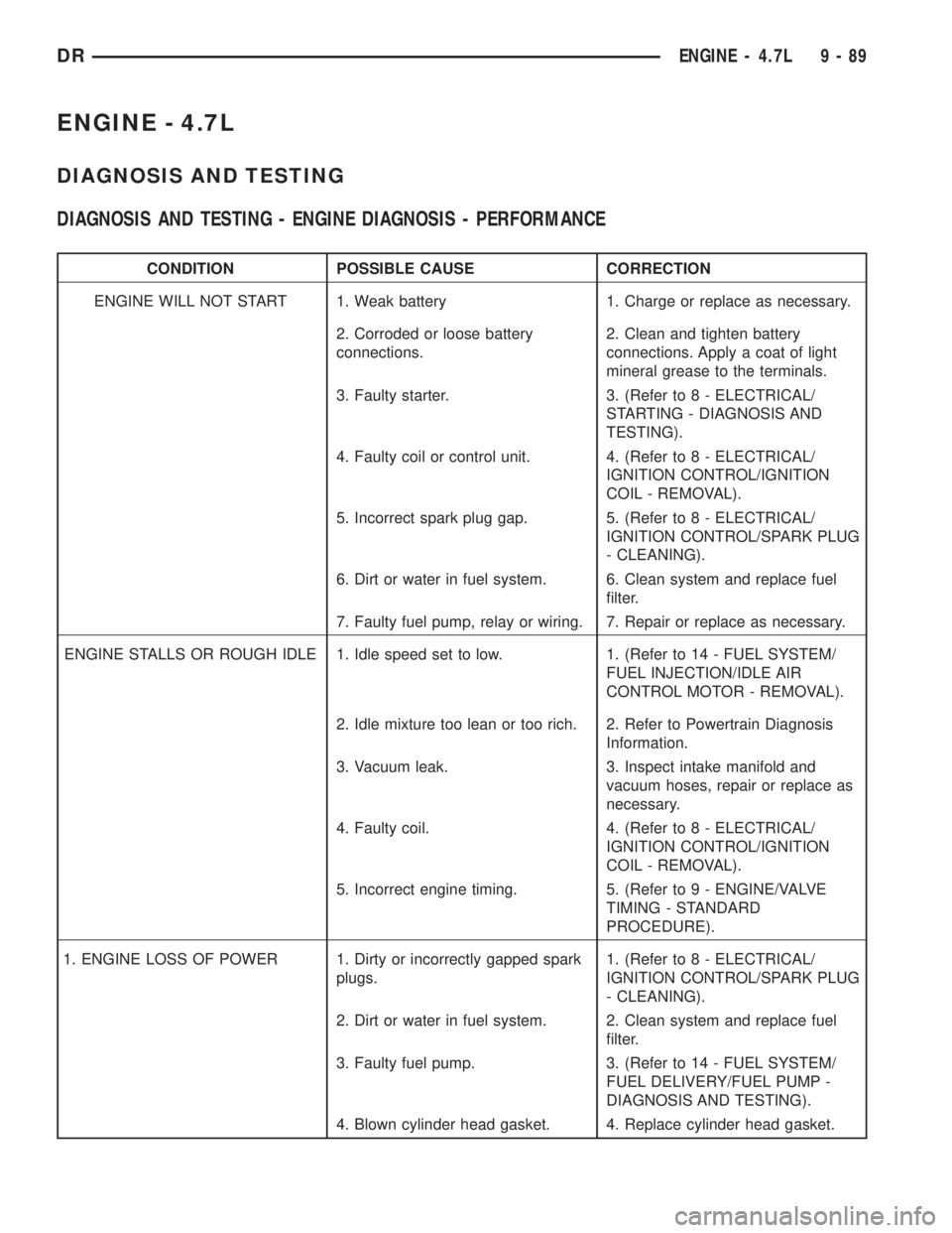
ENGINE - 4.7L
DIAGNOSIS AND TESTING
DIAGNOSIS AND TESTING - ENGINE DIAGNOSIS - PERFORMANCE
CONDITION POSSIBLE CAUSE CORRECTION
ENGINE WILL NOT START 1. Weak battery 1. Charge or replace as necessary.
2. Corroded or loose battery
connections.2. Clean and tighten battery
connections. Apply a coat of light
mineral grease to the terminals.
3. Faulty starter. 3. (Refer to 8 - ELECTRICAL/
STARTING - DIAGNOSIS AND
TESTING).
4. Faulty coil or control unit. 4. (Refer to 8 - ELECTRICAL/
IGNITION CONTROL/IGNITION
COIL - REMOVAL).
5. Incorrect spark plug gap. 5. (Refer to 8 - ELECTRICAL/
IGNITION CONTROL/SPARK PLUG
- CLEANING).
6. Dirt or water in fuel system. 6. Clean system and replace fuel
filter.
7. Faulty fuel pump, relay or wiring. 7. Repair or replace as necessary.
ENGINE STALLS OR ROUGH IDLE 1. Idle speed set to low. 1. (Refer to 14 - FUEL SYSTEM/
FUEL INJECTION/IDLE AIR
CONTROL MOTOR - REMOVAL).
2. Idle mixture too lean or too rich. 2. Refer to Powertrain Diagnosis
Information.
3. Vacuum leak. 3. Inspect intake manifold and
vacuum hoses, repair or replace as
necessary.
4. Faulty coil. 4. (Refer to 8 - ELECTRICAL/
IGNITION CONTROL/IGNITION
COIL - REMOVAL).
5. Incorrect engine timing. 5. (Refer to 9 - ENGINE/VALVE
TIMING - STANDARD
PROCEDURE).
1. ENGINE LOSS OF POWER 1. Dirty or incorrectly gapped spark
plugs.1. (Refer to 8 - ELECTRICAL/
IGNITION CONTROL/SPARK PLUG
- CLEANING).
2. Dirt or water in fuel system. 2. Clean system and replace fuel
filter.
3. Faulty fuel pump. 3. (Refer to 14 - FUEL SYSTEM/
FUEL DELIVERY/FUEL PUMP -
DIAGNOSIS AND TESTING).
4. Blown cylinder head gasket. 4. Replace cylinder head gasket.
DRENGINE - 4.7L 9 - 89
Page 1345 of 2895
INSTALLATION
(1) Position engine in the vehicle.
Position both the left and right side engine mount
brackets and install the through bolts and nuts.
Tighten nuts to4X2 vehicles95 N´m (70 ft. lbs.).
4X4 vehicles102 N´m (75 ft. lbs.).
(2)4X4 vehiclesInstall locknuts onto the engine
mount brackets. Tighten locknuts to 41 N´m (30 ft.
lbs.).
(3) Remove jack from under the transmission.
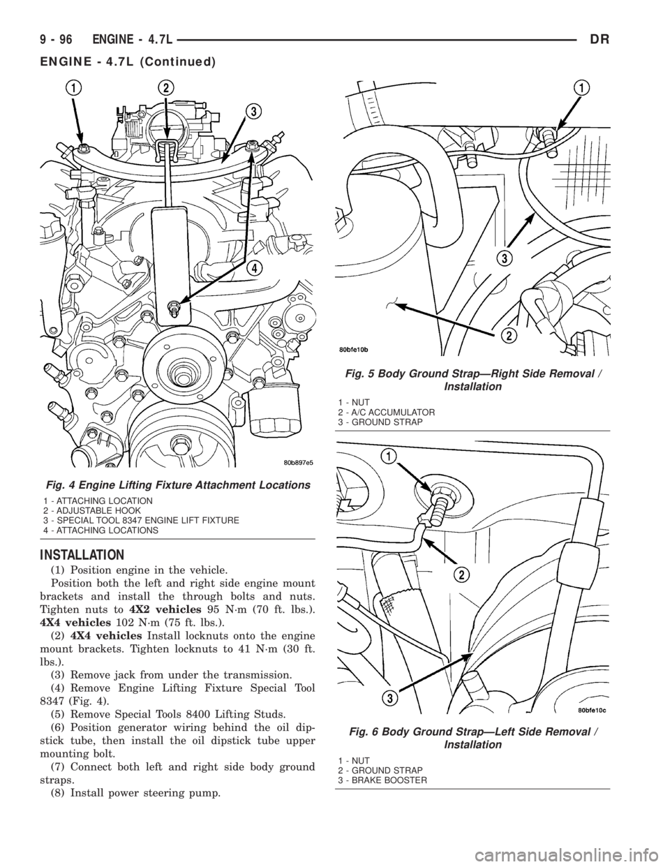
(4) Remove Engine Lifting Fixture Special Tool
8347 (Fig. 4).
(5) Remove Special Tools 8400 Lifting Studs.
(6) Position generator wiring behind the oil dip-
stick tube, then install the oil dipstick tube upper
mounting bolt.
(7) Connect both left and right side body ground
straps.
(8) Install power steering pump.
Fig. 4 Engine Lifting Fixture Attachment Locations
1 - ATTACHING LOCATION
2 - ADJUSTABLE HOOK
3 - SPECIAL TOOL 8347 ENGINE LIFT FIXTURE
4 - ATTACHING LOCATIONS
Fig. 5 Body Ground StrapÐRight Side Removal /
Installation
1 - NUT
2 - A/C ACCUMULATOR
3 - GROUND STRAP
Fig. 6 Body Ground StrapÐLeft Side Removal /
Installation
1 - NUT
2 - GROUND STRAP
3 - BRAKE BOOSTER
9 - 96 ENGINE - 4.7LDR
ENGINE - 4.7L (Continued)
Page 1428 of 2895
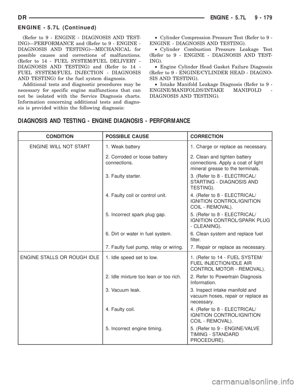
(Refer to 9 - ENGINE - DIAGNOSIS AND TEST-
ING)ÐPERFORMANCE and (Refer to 9 - ENGINE -
DIAGNOSIS AND TESTING)ÐMECHANICAL for
possible causes and corrections of malfunctions.
(Refer to 14 - FUEL SYSTEM/FUEL DELIVERY -
DIAGNOSIS AND TESTING) and (Refer to 14 -
FUEL SYSTEM/FUEL INJECTION - DIAGNOSIS
AND TESTING) for the fuel system diagnosis.
Additional tests and diagnostic procedures may be
necessary for specific engine malfunctions that can
not be isolated with the Service Diagnosis charts.
Information concerning additional tests and diagno-
sis is provided within the following diagnosis:²Cylinder Compression Pressure Test (Refer to 9 -
ENGINE - DIAGNOSIS AND TESTING).
²Cylinder Combustion Pressure Leakage Test
(Refer to 9 - ENGINE - DIAGNOSIS AND TEST-
ING).
²Engine Cylinder Head Gasket Failure Diagnosis
(Refer to 9 - ENGINE/CYLINDER HEAD - DIAGNO-
SIS AND TESTING).
²Intake Manifold Leakage Diagnosis (Refer to 9 -
ENGINE/MANIFOLDS/INTAKE MANIFOLD -
DIAGNOSIS AND TESTING).
DIAGNOSIS AND TESTING - ENGINE DIAGNOSIS - PERFORMANCE
CONDITION POSSIBLE CAUSE CORRECTION
ENGINE WILL NOT START 1. Weak battery 1. Charge or replace as necessary.
2. Corroded or loose battery
connections.2. Clean and tighten battery
connections. Apply a coat of light
mineral grease to the terminals.
3. Faulty starter. 3. (Refer to 8 - ELECTRICAL/
STARTING - DIAGNOSIS AND
TESTING).
4. Faulty coil or control unit. 4. (Refer to 8 - ELECTRICAL/
IGNITION CONTROL/IGNITION
COIL - REMOVAL).
5. Incorrect spark plug gap. 5. (Refer to 8 - ELECTRICAL/
IGNITION CONTROL/SPARK PLUG
- CLEANING).
6. Dirt or water in fuel system. 6. Clean system and replace fuel
filter.
7. Faulty fuel pump, relay or wiring. 7. Repair or replace as necessary.
ENGINE STALLS OR ROUGH IDLE 1. Idle speed set to low. 1. (Refer to 14 - FUEL SYSTEM/
FUEL INJECTION/IDLE AIR
CONTROL MOTOR - REMOVAL).
2. Idle mixture too lean or too rich. 2. Refer to Powertrain Diagnosis
Information.
3. Vacuum leak. 3. Inspect intake manifold and
vacuum hoses, repair or replace as
necessary.
4. Faulty coil. 4. (Refer to 8 - ELECTRICAL/
IGNITION CONTROL/IGNITION
COIL - REMOVAL).
5. Incorrect engine timing. 5. (Refer to 9 - ENGINE/VALVE
TIMING - STANDARD
PROCEDURE).
DRENGINE - 5.7L 9 - 179
ENGINE - 5.7L (Continued)
Page 1483 of 2895
(3) Recover refrigerant from a/c system, if
equipped (Refer to 24 - HEATING & AIR CONDI-
TIONING/PLUMBING - STANDARD PROCEDURE).
(4) Remove the a/c condenser, if equipped (Refer to
24 - HEATING & AIR CONDITIONING/PLUMBING/
A/C CONDENSER - REMOVAL).
(5) Remove the transmission oil cooler (Refer to 7 -
COOLING/TRANSMISSION/TRANS COOLER -
REMOVAL).
(6) Remove the washer bottle from the fan shroud.
(7) Remove the viscous fan/drive (Refer to 7 -
COOLING/ENGINE/RADIATOR FAN - REMOVAL).
(8) Remove radiator (Refer to 7 - COOLING/EN-
GINE/RADIATOR - REMOVAL).
(9) Remove the upper crossmember and top core
support.
(10) Remove the accessory drive belt (Refer to 7 -
COOLING/ACCESSORY DRIVE/DRIVE BELTS -
REMOVAL).
(11) Remove the A/C compressor with the lines
attached. Secure compressor out of the way.
(12) Remove generator assembly (Refer to 8 -
ELECTRICAL/CHARGING/GENERATOR - REMOV-
AL).
(13) Remove the air cleaner resonator and duct
work as an assembly.
(14) Disconnect the throttle linkage (Refer to 14 -
FUEL SYSTEM/FUEL INJECTION/THROTTLE
CONTROL CABLE - REMOVAL).
(15) Remove throttle body (Refer to 14 - FUEL
SYSTEM/FUEL INJECTION/THROTTLE BODY -
REMOVAL).
(16) Remove the intake manifold (Refer to 9 -
ENGINE/MANIFOLDS/INTAKE MANIFOLD -
REMOVAL).
(17) Remove the distributor cap and wiring.
(18) Disconnect the heater hoses.
(19) Disconnect the power steering hoses, if
equipped.
(20) Perform the Fuel System Pressure Release
procedure (Refer to 14 - FUEL SYSTEM/FUEL
DELIVERY - STANDARD PROCEDURE).
(21) Disconnect the fuel supply line (Refer to 14 -
FUEL SYSTEM/FUEL DELIVERY/QUICK CON-
NECT FITTING - STANDARD PROCEDURE).
(22) On Manual Transmission vehicles, remove the
shift lever (Refer to 21 - TRANSMISSION/TRANS-
AXLE/MANUAL/SHIFT COVER - REMOVAL).
(23) Raise and support the vehicle on a hoist and
drain the engine oil.
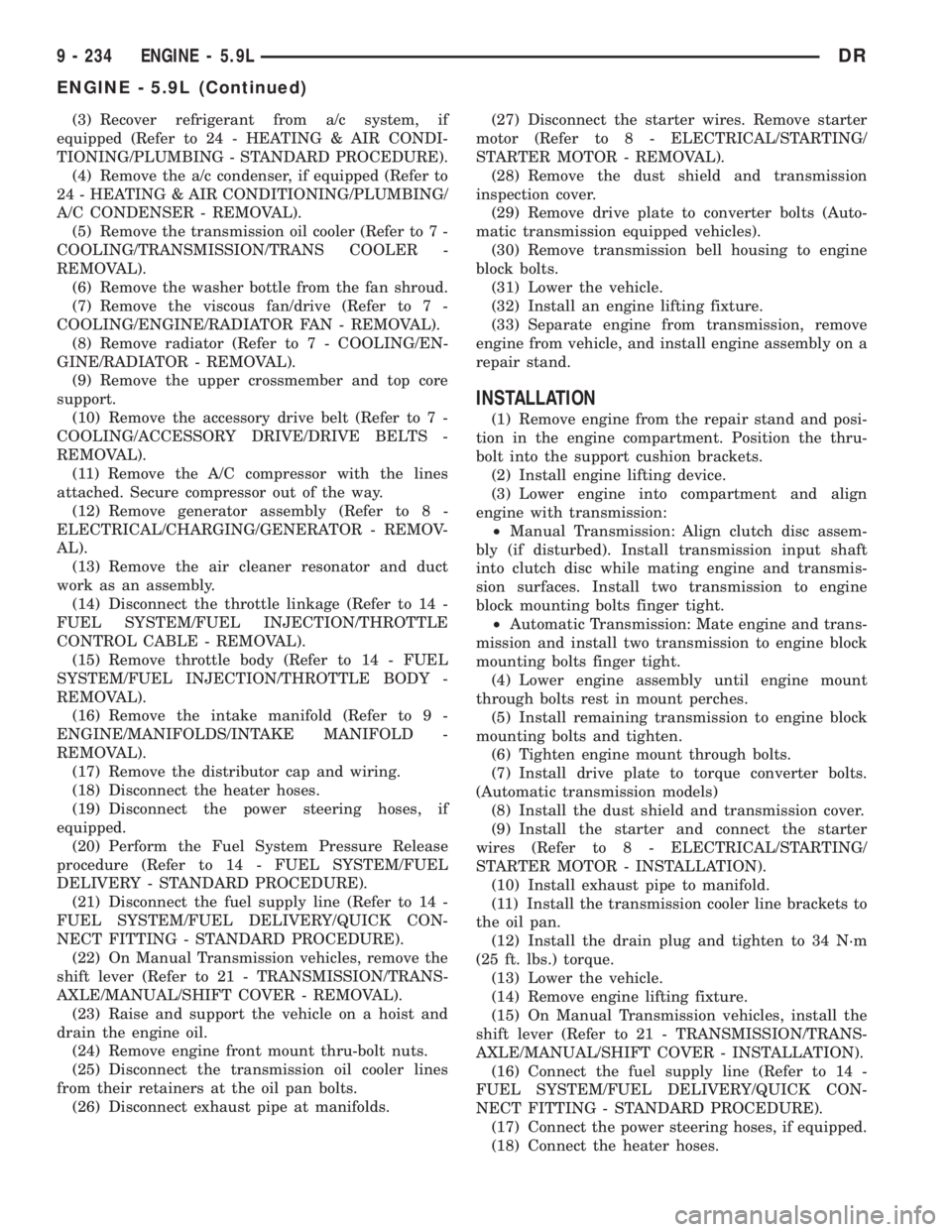
(24) Remove engine front mount thru-bolt nuts.
(25) Disconnect the transmission oil cooler lines
from their retainers at the oil pan bolts.
(26) Disconnect exhaust pipe at manifolds.(27) Disconnect the starter wires. Remove starter
motor (Refer to 8 - ELECTRICAL/STARTING/
STARTER MOTOR - REMOVAL).
(28) Remove the dust shield and transmission
inspection cover.
(29) Remove drive plate to converter bolts (Auto-
matic transmission equipped vehicles).
(30) Remove transmission bell housing to engine
block bolts.
(31) Lower the vehicle.
(32) Install an engine lifting fixture.
(33) Separate engine from transmission, remove
engine from vehicle, and install engine assembly on a
repair stand.
INSTALLATION
(1) Remove engine from the repair stand and posi-
tion in the engine compartment. Position the thru-
bolt into the support cushion brackets.
(2) Install engine lifting device.
(3) Lower engine into compartment and align
engine with transmission:
²Manual Transmission: Align clutch disc assem-
bly (if disturbed). Install transmission input shaft
into clutch disc while mating engine and transmis-
sion surfaces. Install two transmission to engine
block mounting bolts finger tight.
²Automatic Transmission: Mate engine and trans-
mission and install two transmission to engine block
mounting bolts finger tight.
(4) Lower engine assembly until engine mount
through bolts rest in mount perches.
(5) Install remaining transmission to engine block
mounting bolts and tighten.
(6) Tighten engine mount through bolts.
(7) Install drive plate to torque converter bolts.
(Automatic transmission models)
(8) Install the dust shield and transmission cover.
(9) Install the starter and connect the starter
wires (Refer to 8 - ELECTRICAL/STARTING/
STARTER MOTOR - INSTALLATION).
(10) Install exhaust pipe to manifold.
(11) Install the transmission cooler line brackets to
the oil pan.
(12) Install the drain plug and tighten to 34 N´m
(25 ft. lbs.) torque.
(13) Lower the vehicle.
(14) Remove engine lifting fixture.
(15) On Manual Transmission vehicles, install the
shift lever (Refer to 21 - TRANSMISSION/TRANS-
AXLE/MANUAL/SHIFT COVER - INSTALLATION).
(16) Connect the fuel supply line (Refer to 14 -
FUEL SYSTEM/FUEL DELIVERY/QUICK CON-
NECT FITTING - STANDARD PROCEDURE).
(17) Connect the power steering hoses, if equipped.
(18) Connect the heater hoses.
9 - 234 ENGINE - 5.9LDR
ENGINE - 5.9L (Continued)
Page 1484 of 2895
(19) Install the distributor cap and wiring.
(20) Install the intake manifold (Refer to 9 -
ENGINE/MANIFOLDS/INTAKE MANIFOLD -
INSTALLATION).
(21) Using a new gasket, install throttle body
(Refer to 14 - FUEL SYSTEM/FUEL INJECTION/
THROTTLE BODY - INSTALLATION).
(22) Connect the throttle linkage (Refer to 14 -
FUEL SYSTEM/FUEL INJECTION/THROTTLE
CONTROL CABLE - INSTALLATION).
(23) Install the air cleaner resonator and duct
work..
(24) Install the generator and wire connections
(Refer to 8 - ELECTRICAL/CHARGING/GENERA-
TOR - INSTALLATION).
(25) Install a/c compressor and lines (Refer to 24 -
HEATING & AIR CONDITIONING/PLUMBING/A/C
COMPRESSOR - INSTALLATION).
(26) Install the accessory drive belt (Refer to 7 -
COOLING/ACCESSORY DRIVE/DRIVE BELTS -
INSTALLATION).
(27) Install upper radiator support crossmember.
(28) Install radiator (Refer to 7 - COOLING/EN-
GINE/RADIATOR - INSTALLATION).
(29) Connect the radiator lower hose.
(30) Connect the transmission oil cooler lines to
the radiator.
(31) Install the fan shroud.
(32) Install the fan (Refer to 7 - COOLING/EN-
GINE/RADIATOR FAN - INSTALLATION).
(33) Connect the radiator upper hose.
(34) Install the washer bottle.
(35) Install the transmission oil cooler (Refer to 7 -
COOLING/TRANSMISSION/TRANS COOLER -
INSTALLATION).
(36) Connect the transmission cooler lines.
(37) If equipped, install the condenser (Refer to 24
- HEATING & AIR CONDITIONING/PLUMBING/
A/C CONDENSER - INSTALLATION).
(38) Evacuate and charge the air conditioning sys-
tem, if equipped (Refer to 24 - HEATING & AIR
CONDITIONING/PLUMBING - STANDARD PRO-
CEDURE).
(39) Add engine oil to crankcase (Refer to LUBRI-
CATION & MAINTENANCE/FLUID TYPES - SPEC-
IFICATIONS).
(40) Fill cooling system (Refer to 7 - COOLING -
STANDARD PROCEDURE).
(41) Connect battery negative cable.
(42) Start engine and inspect for leaks.
(43) Road test vehicle.SPECIFICATIONS
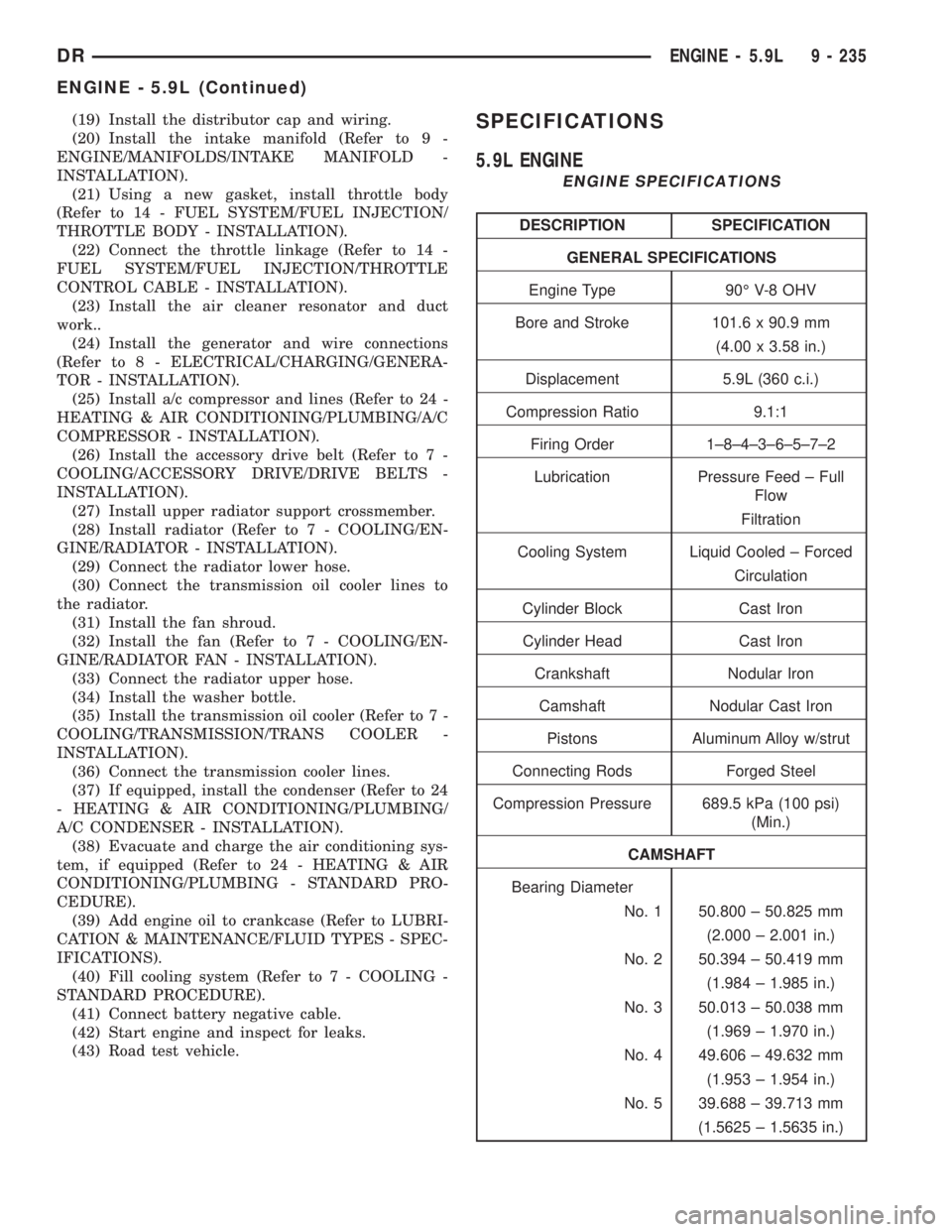
5.9L ENGINE
ENGINE SPECIFICATIONS
DESCRIPTION SPECIFICATION
GENERAL SPECIFICATIONS
Engine Type 90É V-8 OHV
Bore and Stroke 101.6 x 90.9 mm
(4.00 x 3.58 in.)
Displacement 5.9L (360 c.i.)
Compression Ratio 9.1:1
Firing Order 1±8±4±3±6±5±7±2
Lubrication Pressure Feed ± Full
Flow
Filtration
Cooling System Liquid Cooled ± Forced
Circulation
Cylinder Block Cast Iron
Cylinder Head Cast Iron
Crankshaft Nodular Iron
Camshaft Nodular Cast Iron
Pistons Aluminum Alloy w/strut
Connecting Rods Forged Steel
Compression Pressure 689.5 kPa (100 psi)
(Min.)
CAMSHAFT
Bearing Diameter
No. 1 50.800 ± 50.825 mm
(2.000 ± 2.001 in.)
No. 2 50.394 ± 50.419 mm
(1.984 ± 1.985 in.)
No. 3 50.013 ± 50.038 mm
(1.969 ± 1.970 in.)
No. 4 49.606 ± 49.632 mm
(1.953 ± 1.954 in.)
No. 5 39.688 ± 39.713 mm
(1.5625 ± 1.5635 in.)
DRENGINE - 5.9L 9 - 235
ENGINE - 5.9L (Continued)
Page 1595 of 2895
(4) Remove dipstick support at fuel filter housing.
Position dipstick tube to the side.
(5) Disconnect the air grid heater power cables at
the cable mounting studs.
(6) Disconnect the ground strap at the intake
cover.
(7) Remove the engine wiring harness connections
at the air inlet housing elbow.
(8) Remove the four (4) air inlet housing mounting
bolts and remove the housing from top of the heater
elements.
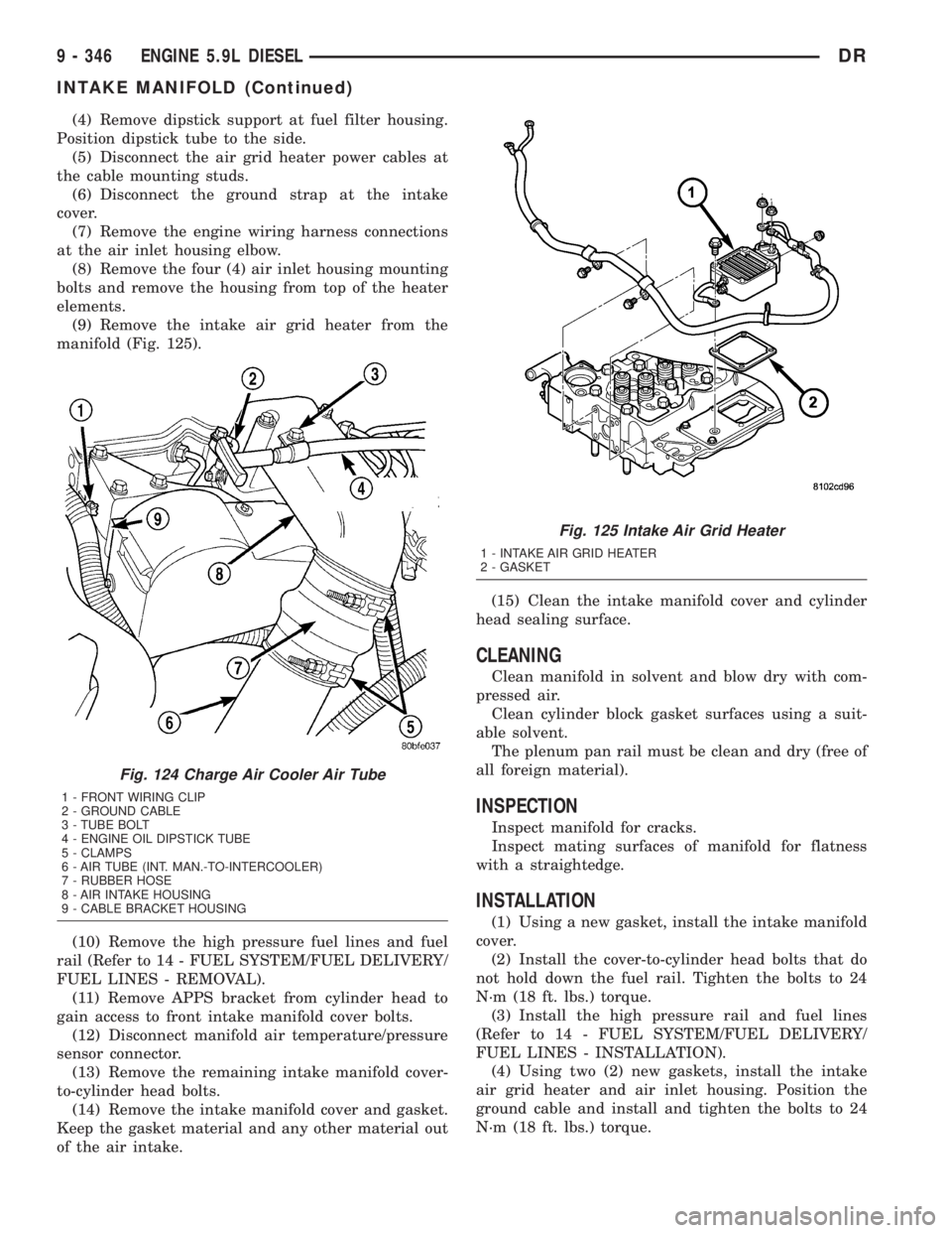
(9) Remove the intake air grid heater from the
manifold (Fig. 125).
(10) Remove the high pressure fuel lines and fuel
rail (Refer to 14 - FUEL SYSTEM/FUEL DELIVERY/
FUEL LINES - REMOVAL).
(11) Remove APPS bracket from cylinder head to
gain access to front intake manifold cover bolts.
(12) Disconnect manifold air temperature/pressure
sensor connector.
(13) Remove the remaining intake manifold cover-
to-cylinder head bolts.
(14) Remove the intake manifold cover and gasket.
Keep the gasket material and any other material out
of the air intake.(15) Clean the intake manifold cover and cylinder
head sealing surface.
CLEANING
Clean manifold in solvent and blow dry with com-
pressed air.
Clean cylinder block gasket surfaces using a suit-
able solvent.
The plenum pan rail must be clean and dry (free of
all foreign material).
INSPECTION
Inspect manifold for cracks.
Inspect mating surfaces of manifold for flatness
with a straightedge.
INSTALLATION
(1) Using a new gasket, install the intake manifold
cover.
(2) Install the cover-to-cylinder head bolts that do
not hold down the fuel rail. Tighten the bolts to 24
N´m (18 ft. lbs.) torque.
(3) Install the high pressure rail and fuel lines
(Refer to 14 - FUEL SYSTEM/FUEL DELIVERY/
FUEL LINES - INSTALLATION).
(4) Using two (2) new gaskets, install the intake
air grid heater and air inlet housing. Position the
ground cable and install and tighten the bolts to 24
N´m (18 ft. lbs.) torque.
Fig. 124 Charge Air Cooler Air Tube
1 - FRONT WIRING CLIP
2 - GROUND CABLE
3 - TUBE BOLT
4 - ENGINE OIL DIPSTICK TUBE
5 - CLAMPS
6 - AIR TUBE (INT. MAN.-TO-INTERCOOLER)
7 - RUBBER HOSE
8 - AIR INTAKE HOUSING
9 - CABLE BRACKET HOUSING
Fig. 125 Intake Air Grid Heater
1 - INTAKE AIR GRID HEATER
2 - GASKET
9 - 346 ENGINE 5.9L DIESELDR
INTAKE MANIFOLD (Continued)
Page 1660 of 2895
REMOVAL
REMOVAL
WARNING: IF TORCHES ARE USED WHEN WORK-
ING ON THE EXHAUST SYSTEM, DO NOT ALLOW
THE FLAME NEAR THE FUEL LINES.
(1) Raise and support the vehicle.
(2) Saturate the bolts and nuts with heat valve
lubricant. Allow 5 minutes for penetration.
(3) Remove the bolts from the crossover pipe to the
catalytic converter connection.
(4) Disconnect oxygen sensor wiring.
(5) Loosen the nuts from the clamp that hold the
catalytic converter to the exhaust pipe flange connec-
tion.
NOTE: Do not remove nut from T-Bolt. Only remove
nut far enough, so that the T end can be removed
from the clamp.
(6) Remove the T bolt end of the fastener, from the
clamp.
(7) Spread the clamp, and remove the catalytic
converter from the vehicle.
(8) Discard the clamp.
NOTE: The catalytic converter to exhaust manifold
clamp is not reusable. Always use a new clamp
when reinstalling the catalytic converter.
REMOVAL
(1) Raise and support vehicle.
(2) Saturate the bolts and nuts with heat valve
lubricant. Allow 5 minutes for penetration.
(3) Remove clamps and nuts.
(4) Remove the catalytic converter.
INSPECTION
Look at the stainless steel body of the converter,
inspect for bulging or other distortion that could be a
result of overheating. If the converter has a heat
shield attached make sure it is not bent or loose.
If you suspect internal damage to the catalyst, tap-
ping the bottom of the catalyst with a rubber mallet
may indicate a damaged core.
INSTALLATION
INSTALLATION
NOTE: The catalytic converter to exhaust manifold
clamp is not reusable. Always use a new clamp
when reinstalling the catalytic converter.(1) Position the catalytic converter onto the
exhaust pipe flange connection. Tighten the nuts to
28 N´m (250 in. lbs.) torque.
(2) Install the muffler onto the catalytic converter
until the alignment tab is inserted into the align-
ment slot.
(3) Install the exhaust clamp at the muffler and
catalytic converter connection. Tighten the clamp
nuts to 47 N´m (35 ft. lbs.) torque.
(4) Connect oxygen sensor wiring.
(5) Lower the vehicle.
(6) Start the engine and inspect for exhaust leaks
and exhaust system contact with the body panels.
Adjust the alignment, if needed.
INSTALLATION
(1) Assemble converter and clamps loosely in
place.
(2) Install the exhaust pipe onto exhaust mani-
folds, tighten 31 N´m (23 ft. lbs.).
(3) Tighten all clamp nuts to 48 N´m (35 ft. lbs.)
torque.
(4) Lower the vehicle.
(5) Start the engine and inspect for exhaust leaks
and exhaust system contact with the body panels. A
minimum of 25.4 mm (1.0 in.) is required between
exhaust system components and body/frame parts.
Adjust the alignment, if needed.
EXHAUST PIPE
REMOVAL
REMOVAL Ð 5.9L
(1) Raise and support the vehicle.
(2) Saturate the bolts and nuts with heat valve
lubricant. Allow 5 minutes for penetration.
(3) Remove exhaust pipe to manifold bolts, retain-
ers and nuts.
(4) Remove the clamp nuts.
(5) Remove the exhaust pipe (Fig. 1).
REMOVAL
CAUTION: When servicing or replacing exhaust
system components, disconnect the oxygen sensor
connector(s). Allowing the exhaust to hang by the
oxygen sensor wires will damage the harness
and/or sensor.
(1) Raise and support the vehicle.
(2) Saturate the bolts and nuts with MopartRust
Penetrant. Allow 5 minutes for penetration.
(3) Disconnect the oxygen sensor(s).
DREXHAUST SYSTEM 11 - 5
CATALYTIC CONVERTER (Continued)
Page 1687 of 2895
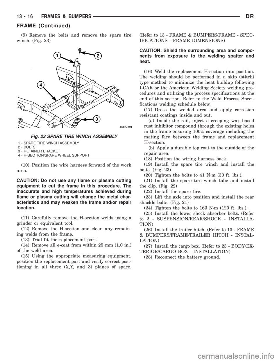
(9) Remove the bolts and remove the spare tire
winch. (Fig. 23)
(10) Position the wire harness forward of the work
area.
CAUTION: Do not use any flame or plasma cutting
equipment to cut the frame in this procedure. The
inaccurate and high temperatures achieved during
flame or plasma cutting will change the metal char-
acteristics and may weaken the frame and/or repair
location.
(11) Carefully remove the H-section welds using a
grinder or equivalent tool.
(12) Remove the H-section and clean any remain-
ing welds from the frame.
(13) Trial fit the replacement part.
(14) Remove all e-coat from within 25 mm (1.0 in.)
of the weld area.
(15) Using the appropriate measuring equipment,
position the replacement part and verify correct posi-
tioning in all three (X,Y, and Z) planes of space.(Refer to 13 - FRAME & BUMPERS/FRAME - SPEC-
IFICATIONS - FRAME DIMENSIONS)
CAUTION: Shield the surrounding area and compo-
nents from exposure to the welding spatter and
heat.
(16) Weld the replacement H-section into position.
The welding should be performed in a skip (stitch)
type method to minimize the heat buildup following
I-CAR or the American Welding Society welding pro-
cedures and utilizing the process specifications at the
end of this section. Refer to the Weld Process Speci-
fications welding schedule below.
(17) Dress the welded area and apply corrosion
resistant coatings inside and out.
(a) Inside the rail, inject a creeping wax based
rust inhibitor compound through the existing holes
in the frame ensuring 100% coverage including the
mating face between the frame and replacement
H-section.
(b) Apply a durable top coat to the outside of the
repair area.
(18) Position the wiring harness back.
(19) Install the spare tire winch and install the
bolts. (Fig. 23)
(20) Tighten the bolts to 41 N´m (30 ft. lbs.).
(21) Install the spare tire winch tube and install
the clip. (Fig. 22)
(22) Install the spare tire.
(23) Lift the axle into position and install the rear
shackle bolts. (Fig. 21)
(24) Tighten the bolts to 163 N´m (120 ft. lbs.).
(25) Install the lower shock absorber bolts. (Refer
to 2 - SUSPENSION/REAR/SHOCK - INSTALLA-
TION)
(26) Install the trailer hitch. (Refer to 13 - FRAME
& BUMPERS/FRAME/TRAILER HITCH - INSTAL-
LATION)
(27) Install the cargo box. (Refer to 23 - BODY/EX-
TERIOR/CARGO BOX - INSTALLATION)
(28) Reconnect the battery ground.
Fig. 23 SPARE TIRE WINCH ASSEMBLY
1 - SPARE TIRE WINCH ASSEMBLY
2 - BOLTS
3 - RETAINER BRACKET
4 - H-SECTION/SPARE WHEEL SUPPORT
13 - 16 FRAMES & BUMPERSDR
FRAME (Continued)
Page 1704 of 2895
pump.Refer to Fuel Pump - Description and
Operation for more information.
If fuel pressure at the pressure regulator exceeds
approximately 49.2 psi, an internal diaphragm opens
and excess fuel pressure is routed back into the tank
through the bottom of pressure regulator.
Both fuel filters (at bottom of fuel pump module
and within fuel pressure regulator) are designed for
extended service. They do not require normal sched-
uled maintenance. Filters should only be replaced if
a diagnostic procedure indicates to do so.
FUEL LEVEL SENDING UNIT /
SENSOR
DESCRIPTION
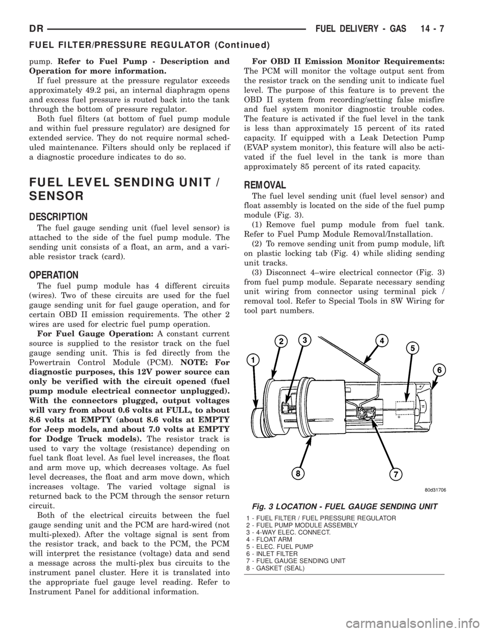
The fuel gauge sending unit (fuel level sensor) is
attached to the side of the fuel pump module. The
sending unit consists of a float, an arm, and a vari-
able resistor track (card).
OPERATION
The fuel pump module has 4 different circuits
(wires). Two of these circuits are used for the fuel
gauge sending unit for fuel gauge operation, and for
certain OBD II emission requirements. The other 2
wires are used for electric fuel pump operation.
For Fuel Gauge Operation:A constant current
source is supplied to the resistor track on the fuel
gauge sending unit. This is fed directly from the
Powertrain Control Module (PCM).NOTE: For
diagnostic purposes, this 12V power source can
only be verified with the circuit opened (fuel
pump module electrical connector unplugged).
With the connectors plugged, output voltages
will vary from about 0.6 volts at FULL, to about
8.6 volts at EMPTY (about 8.6 volts at EMPTY
for Jeep models, and about 7.0 volts at EMPTY
for Dodge Truck models).The resistor track is
used to vary the voltage (resistance) depending on
fuel tank float level. As fuel level increases, the float
and arm move up, which decreases voltage. As fuel
level decreases, the float and arm move down, which
increases voltage. The varied voltage signal is
returned back to the PCM through the sensor return
circuit.
Both of the electrical circuits between the fuel
gauge sending unit and the PCM are hard-wired (not
multi-plexed). After the voltage signal is sent from
the resistor track, and back to the PCM, the PCM
will interpret the resistance (voltage) data and send
a message across the multi-plex bus circuits to the
instrument panel cluster. Here it is translated into
the appropriate fuel gauge level reading. Refer to
Instrument Panel for additional information.For OBD II Emission Monitor Requirements:
The PCM will monitor the voltage output sent from
the resistor track on the sending unit to indicate fuel
level. The purpose of this feature is to prevent the
OBD II system from recording/setting false misfire
and fuel system monitor diagnostic trouble codes.
The feature is activated if the fuel level in the tank
is less than approximately 15 percent of its rated
capacity. If equipped with a Leak Detection Pump
(EVAP system monitor), this feature will also be acti-
vated if the fuel level in the tank is more than
approximately 85 percent of its rated capacity.
REMOVAL
The fuel level sending unit (fuel level sensor) and
float assembly is located on the side of the fuel pump
module (Fig. 3).
(1) Remove fuel pump module from fuel tank.
Refer to Fuel Pump Module Removal/Installation.
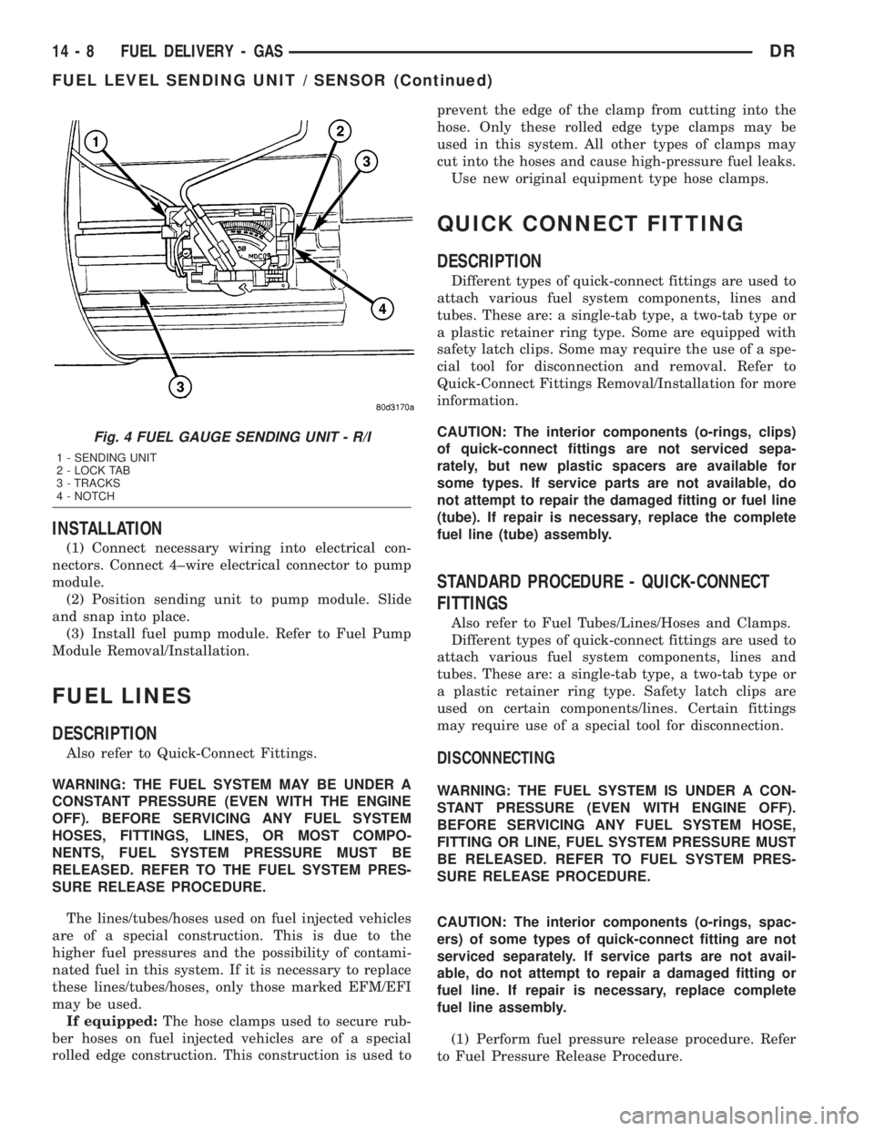
(2) To remove sending unit from pump module, lift
on plastic locking tab (Fig. 4) while sliding sending
unit tracks.
(3) Disconnect 4±wire electrical connector (Fig. 3)
from fuel pump module. Separate necessary sending
unit wiring from connector using terminal pick /
removal tool. Refer to Special Tools in 8W Wiring for
tool part numbers.
Fig. 3 LOCATION - FUEL GAUGE SENDING UNIT
1 - FUEL FILTER / FUEL PRESSURE REGULATOR
2 - FUEL PUMP MODULE ASSEMBLY
3 - 4-WAY ELEC. CONNECT.
4 - FLOAT ARM
5 - ELEC. FUEL PUMP
6 - INLET FILTER
7 - FUEL GAUGE SENDING UNIT
8 - GASKET (SEAL)
DRFUEL DELIVERY - GAS 14 - 7
FUEL FILTER/PRESSURE REGULATOR (Continued)
Page 1705 of 2895
INSTALLATION
(1) Connect necessary wiring into electrical con-
nectors. Connect 4±wire electrical connector to pump
module.
(2) Position sending unit to pump module. Slide
and snap into place.
(3) Install fuel pump module. Refer to Fuel Pump
Module Removal/Installation.
FUEL LINES
DESCRIPTION
Also refer to Quick-Connect Fittings.
WARNING: THE FUEL SYSTEM MAY BE UNDER A
CONSTANT PRESSURE (EVEN WITH THE ENGINE
OFF). BEFORE SERVICING ANY FUEL SYSTEM
HOSES, FITTINGS, LINES, OR MOST COMPO-
NENTS, FUEL SYSTEM PRESSURE MUST BE
RELEASED. REFER TO THE FUEL SYSTEM PRES-
SURE RELEASE PROCEDURE.
The lines/tubes/hoses used on fuel injected vehicles
are of a special construction. This is due to the
higher fuel pressures and the possibility of contami-
nated fuel in this system. If it is necessary to replace
these lines/tubes/hoses, only those marked EFM/EFI
may be used.
If equipped:The hose clamps used to secure rub-
ber hoses on fuel injected vehicles are of a special
rolled edge construction. This construction is used toprevent the edge of the clamp from cutting into the
hose. Only these rolled edge type clamps may be
used in this system. All other types of clamps may
cut into the hoses and cause high-pressure fuel leaks.
Use new original equipment type hose clamps.
QUICK CONNECT FITTING
DESCRIPTION
Different types of quick-connect fittings are used to
attach various fuel system components, lines and
tubes. These are: a single-tab type, a two-tab type or
a plastic retainer ring type. Some are equipped with
safety latch clips. Some may require the use of a spe-
cial tool for disconnection and removal. Refer to
Quick-Connect Fittings Removal/Installation for more
information.
CAUTION: The interior components (o-rings, clips)
of quick-connect fittings are not serviced sepa-
rately, but new plastic spacers are available for
some types. If service parts are not available, do
not attempt to repair the damaged fitting or fuel line
(tube). If repair is necessary, replace the complete
fuel line (tube) assembly.
STANDARD PROCEDURE - QUICK-CONNECT
FITTINGS
Also refer to Fuel Tubes/Lines/Hoses and Clamps.
Different types of quick-connect fittings are used to
attach various fuel system components, lines and
tubes. These are: a single-tab type, a two-tab type or
a plastic retainer ring type. Safety latch clips are
used on certain components/lines. Certain fittings
may require use of a special tool for disconnection.
DISCONNECTING
WARNING: THE FUEL SYSTEM IS UNDER A CON-
STANT PRESSURE (EVEN WITH ENGINE OFF).
BEFORE SERVICING ANY FUEL SYSTEM HOSE,
FITTING OR LINE, FUEL SYSTEM PRESSURE MUST
BE RELEASED. REFER TO FUEL SYSTEM PRES-
SURE RELEASE PROCEDURE.
CAUTION: The interior components (o-rings, spac-
ers) of some types of quick-connect fitting are not
serviced separately. If service parts are not avail-
able, do not attempt to repair a damaged fitting or
fuel line. If repair is necessary, replace complete
fuel line assembly.
(1) Perform fuel pressure release procedure. Refer
to Fuel Pressure Release Procedure.
Fig. 4 FUEL GAUGE SENDING UNIT - R/I
1 - SENDING UNIT
2 - LOCK TAB
3 - TRACKS
4 - NOTCH
14 - 8 FUEL DELIVERY - GASDR
FUEL LEVEL SENDING UNIT / SENSOR (Continued)