Engine Intake Manifold DODGE RAM 2003 Service Owner's Manual
[x] Cancel search | Manufacturer: DODGE, Model Year: 2003, Model line: RAM, Model: DODGE RAM 2003Pages: 2895, PDF Size: 83.15 MB
Page 482 of 2895
(6)If necessary, install throttle body air tube or box.
KNOCK SENSOR
DESCRIPTION
The sensors are used only with 3.7L V-6, 4.7L V-8
and 5.7L V-8 engines. On 3.7L V-6 and 4.7L V-8
engines, the 2 knock sensors are bolted into the cyl-
inder block under the intake manifold.
On 5.7L V-8 engines, 2 knock sensors are also
used. These are bolted into each side of the cylinder
block (outside) under the exhaust manifold.
OPERATION
3.7L V-6 / 4.7L V-8 / 5.7L V-8 Engines Only
Two knock sensors are used; one for each cylinder
bank. When the knock sensor detects a knock in one
of the cylinders on the corresponding bank, it sends
an input signal to the Powertrain Control Module
(PCM). In response, the PCM retards ignition timing
for all cylinders by a scheduled amount.
Knock sensors contain a piezoelectric material
which constantly vibrates and sends an input voltage
(signal) to the PCM while the engine operates. As the
intensity of the crystal's vibration increases, the
knock sensor output voltage also increases.The voltage signal produced by the knock sensor
increases with the amplitude of vibration. The PCM
receives the knock sensor voltage signal as an input.
If the signal rises above a predetermined level, the
PCM will store that value in memory and retard
ignition timing to reduce engine knock. If the knock
sensor voltage exceeds a preset value, the PCM
retards ignition timing for all cylinders. It is not a
selective cylinder retard.
The PCM ignores knock sensor input during engine
idle conditions. Once the engine speed exceeds a
specified value, knock retard is allowed.
Knock retard uses its own short term and long
term memory program.
Long term memory stores previous detonation
information in its battery-backed RAM. The maxi-
mum authority that long term memory has over tim-
ing retard can be calibrated.
Short term memory is allowed to retard timing up
to a preset amount under all operating conditions (as
long as rpm is above the minimum rpm) except at
Wide Open Throttle (WOT). The PCM, using short
term memory, can respond quickly to retard timing
when engine knock is detected. Short term memory
is lost any time the ignition key is turned off.
NOTE: Over or under tightening the sensor mount-
ing bolts will affect knock sensor performance, pos-
sibly causing improper spark control. Always use
the specified torque when installing the knock sen-
sors.
REMOVAL
3.7L V-6 / 4.7L V-8
The 2 knock sensors are bolted into the cylinder
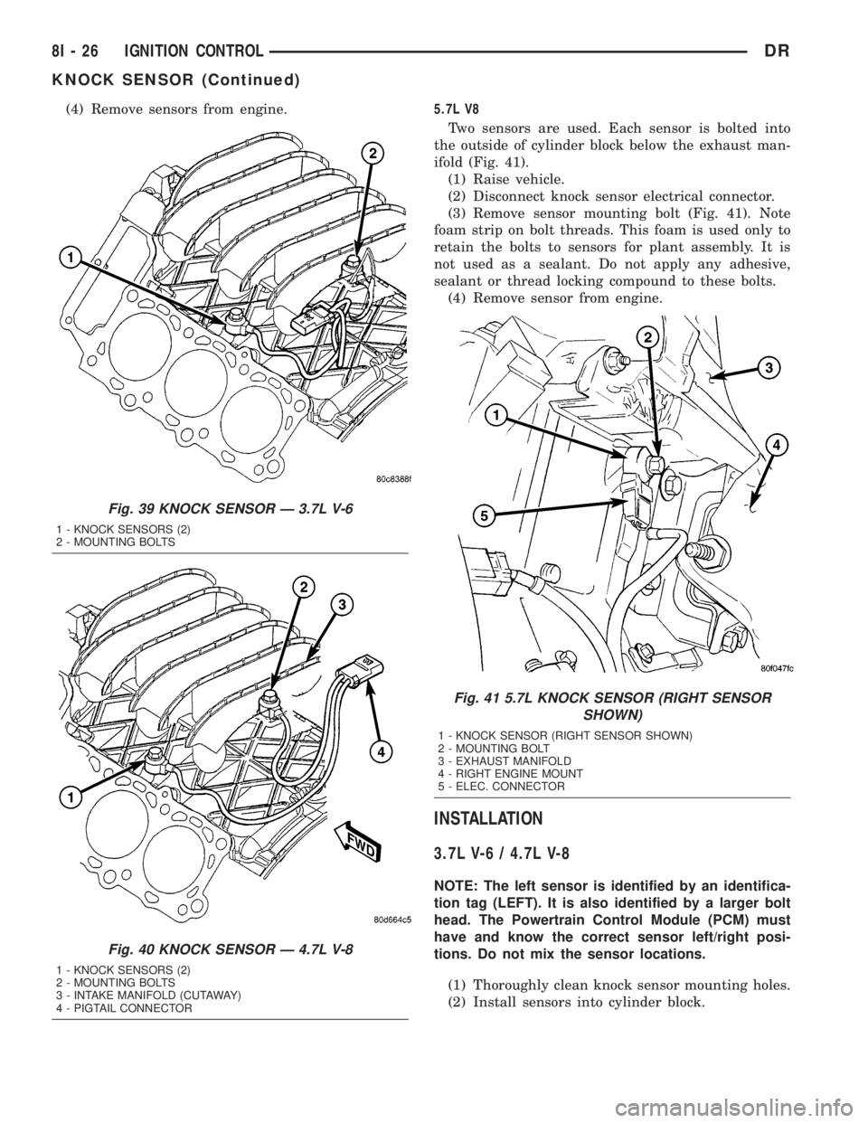
block under the intake manifold (Fig. 39). or (Fig.
40).
NOTE: The left sensor is identified by an identifica-
tion tag (LEFT). It is also identified by a larger bolt
head. The Powertrain Control Module (PCM) must
have and know the correct sensor left/right posi-
tions. Do not mix the sensor locations.
(1) Disconnect knock sensor dual pigtail harness
from engine wiring harness. This connection is made
near rear of engine.
(2) Remove intake manifold. Refer to Engine sec-
tion.
(3) Remove sensor mounting bolts (Fig. 39), or
(Fig. 40). Note foam strip on bolt threads. This foam
is used only to retain the bolts to sensors for plant
assembly. It is not used as a sealant. Do not apply
any adhesive, sealant or thread locking compound to
these bolts.
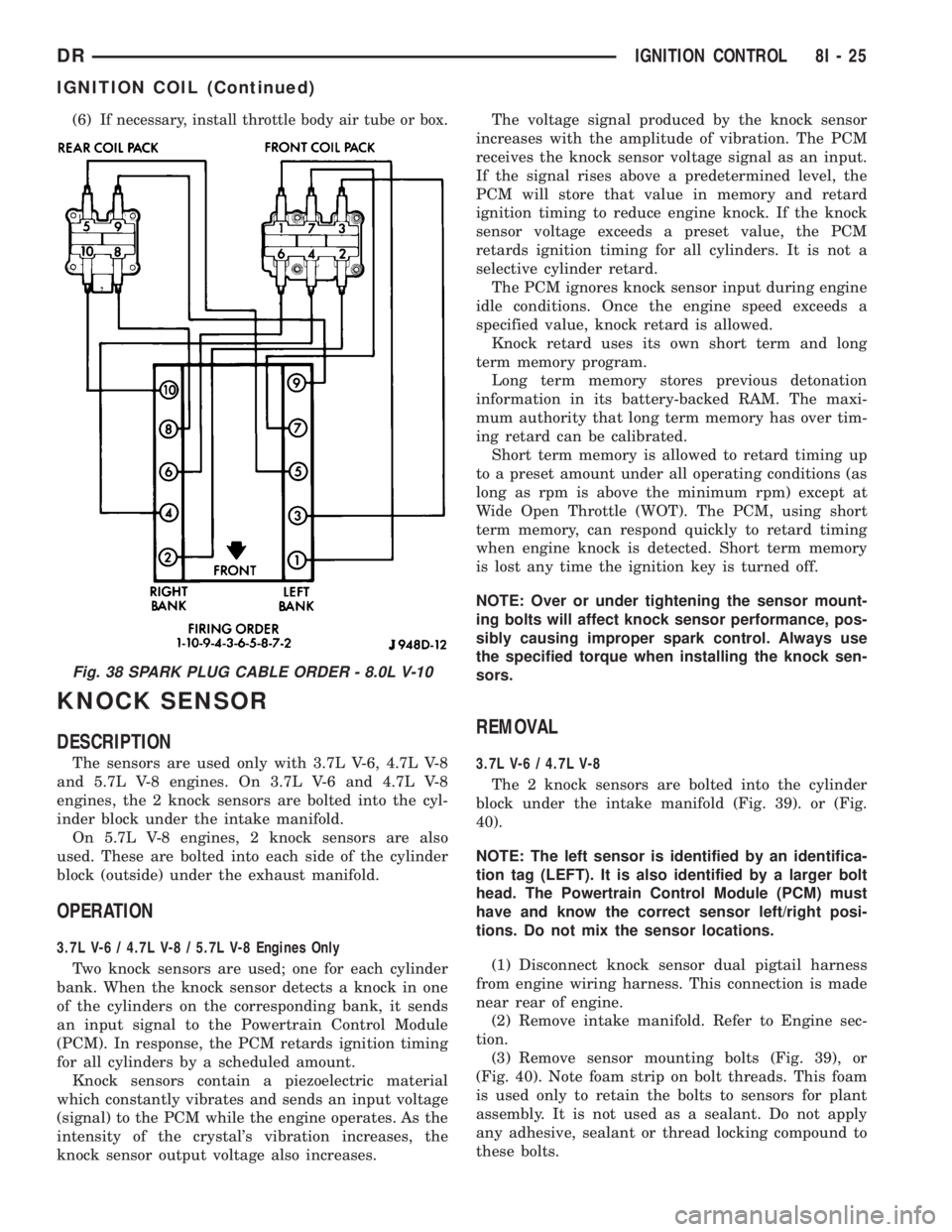
Fig. 38 SPARK PLUG CABLE ORDER - 8.0L V-10
DRIGNITION CONTROL 8I - 25
IGNITION COIL (Continued)
Page 483 of 2895
(4) Remove sensors from engine.5.7L V8
Two sensors are used. Each sensor is bolted into
the outside of cylinder block below the exhaust man-
ifold (Fig. 41).
(1) Raise vehicle.
(2) Disconnect knock sensor electrical connector.
(3) Remove sensor mounting bolt (Fig. 41). Note
foam strip on bolt threads. This foam is used only to
retain the bolts to sensors for plant assembly. It is
not used as a sealant. Do not apply any adhesive,
sealant or thread locking compound to these bolts.
(4) Remove sensor from engine.
INSTALLATION
3.7L V-6 / 4.7L V-8
NOTE: The left sensor is identified by an identifica-
tion tag (LEFT). It is also identified by a larger bolt
head. The Powertrain Control Module (PCM) must
have and know the correct sensor left/right posi-
tions. Do not mix the sensor locations.
(1) Thoroughly clean knock sensor mounting holes.
(2) Install sensors into cylinder block.
Fig. 39 KNOCK SENSOR Ð 3.7L V-6
1 - KNOCK SENSORS (2)
2 - MOUNTING BOLTS
Fig. 40 KNOCK SENSOR Ð 4.7L V-8
1 - KNOCK SENSORS (2)
2 - MOUNTING BOLTS
3 - INTAKE MANIFOLD (CUTAWAY)
4 - PIGTAIL CONNECTOR
Fig. 41 5.7L KNOCK SENSOR (RIGHT SENSOR
SHOWN)
1 - KNOCK SENSOR (RIGHT SENSOR SHOWN)
2 - MOUNTING BOLT
3 - EXHAUST MANIFOLD
4 - RIGHT ENGINE MOUNT
5 - ELEC. CONNECTOR
8I - 26 IGNITION CONTROLDR
KNOCK SENSOR (Continued)
Page 484 of 2895
NOTE: Over or under tightening the sensor mount-
ing bolts will affect knock sensor performance, pos-
sibly causing improper spark control. Always use
the specified torque when installing the knock sen-
sors. The torque for the knock senor bolt is rela-
tively light for an 8mm bolt.
NOTE: Note foam strip on bolt threads. This foam is
used only to retain the bolts to sensors for plant
assembly. It is not used as a sealant. Do not apply
any adhesive, sealant or thread locking compound
to these bolts.
(3) Install and tighten mounting bolts. Refer to
torque specification.
(4) Install intake manifold. Refer to Engine sec-
tion.
(5) Connect knock sensor wiring harness to engine
harness at rear of intake manifold.
5.7L V-8
(1) Thoroughly clean knock sensor mounting hole.
(2) Install sensor into cylinder block.
NOTE: Over or under tightening the sensor mount-
ing bolts will affect knock sensor performance, pos-
sibly causing improper spark control. Always use
the specified torque when installing the knock sen-
sors. The torque for the knock senor bolt is rela-
tively light for an 8mm bolt.
NOTE: Note foam strip on bolt threads. This foam is
used only to retain the bolts to sensors for plant
assembly. It is not used as a sealant. Do not apply
any adhesive, sealant or thread locking compound
to these bolts.
(3) Install and tighten mounting bolt. Refer to
torque specification.
(4) Install electrical connector to sensor.
SPARK PLUG
DESCRIPTION
Resistor type spark plugs are used on all engines.
Sixteen spark plugs (2 per cylinder) are used with
5.7L V-8 engines.
DIAGNOSIS AND TESTING - SPARK PLUG
CONDITIONS
To prevent possible pre-ignition and/or mechanical
engine damage, the correct type/heat range/number
spark plug must be used.
Always use the recommended torque when tighten-
ing spark plugs. Incorrect torque can distort the
spark plug and change plug gap. It can also pull the
plug threads and do possible damage to both the
spark plug and the cylinder head.
Remove the spark plugs and examine them for
burned electrodes and fouled, cracked or broken por-
celain insulators. Keep plugs arranged in the order
in which they were removed from the engine. A sin-
gle plug displaying an abnormal condition indicates
that a problem exists in the corresponding cylinder.
Replace spark plugs at the intervals recommended in
the Lubrication and Maintenance section.
Spark plugs that have low mileage may be cleaned
and reused if not otherwise defective, carbon or oil
fouled.
CAUTION: Never use a motorized wire wheel brush
to clean the spark plugs. Metallic deposits will
remain on the spark plug insulator and will cause
plug misfire.
Spark plug resistance values range from 6,000 to
20,000 ohms (when checked with at least a 1000 volt
spark plug tester).Do not use an ohmmeter to
check the resistance values of the spark plugs.
Inaccurate readings will result.
NORMAL OPERATING
The few deposits present on the spark plug will
probably be light tan or slightly gray in color. This is
evident with most grades of commercial gasoline
(Fig. 42). There will not be evidence of electrode
burning. Gap growth will not average more than
approximately 0.025 mm (.001 in) per 3200 km (2000
miles) of operation. Spark plugs that have normal
wear can usually be cleaned, have the electrodes
filed, have the gap set and then be installed.
Some fuel refiners in several areas of the United
States have introduced a manganese additive (MMT)
for unleaded fuel. During combustion, fuel with MMT
causes the entire tip of the spark plug to be coated
with a rust colored deposit. This rust color can be
misdiagnosed as being caused by coolant in the com-
bustion chamber. Spark plug performance may be
affected by MMT deposits.
DRIGNITION CONTROL 8I - 27
KNOCK SENSOR (Continued)
Page 534 of 2895

reads from ª8º to ª18º volts. An International Control
and Display Symbol icon for ªBattery Charging Con-
ditionº is located on the cluster overlay, directly
below the right end of the gauge scale. The voltage
gauge graphics are black against a white field except
for a single red graduation at each end of the gauge
scale, making them clearly visible within the instru-
ment cluster in daylight. When illuminated from
behind by the panel lamps dimmer controlled cluster
illumination lighting with the exterior lamps turned
On, the black graphics appear blue and the red
graphics still appear red. The orange gauge needle is
internally illuminated. Gauge illumination is pro-
vided by replaceable incandescent bulb and bulb
holder units located on the instrument cluster elec-
tronic circuit board. The voltage gauge is serviced as
a unit with the instrument cluster.
OPERATION
The voltage gauge gives an indication to the vehi-
cle operator of the electrical system voltage. This
gauge is controlled by the instrument cluster circuit
board based upon cluster programming and elec-
tronic messages received by the cluster from the
Powertrain Control Module (PCM) on vehicles
equipped with a gasoline engine, or from the Engine
Control Module (ECM) on vehicles equipped with a
diesel engine over the Programmable Communica-
tions Interface (PCI) data bus. The voltage gauge is
an air core magnetic unit that receives battery cur-
rent on the instrument cluster electronic circuit
board through the fused ignition switch output (run-
start) circuit whenever the ignition switch is in the
On or Start positions. The cluster is programmed to
move the gauge needle back to the left end of the
scale after the ignition switch is turned to the Off
position. The instrument cluster circuitry controls
the gauge needle position and provides the following
features:
²System Voltage Message- Each time the clus-
ter receives a system voltage message from the PCM
or ECM indicating the system voltage is between
about 9.5 volts and about 15 volts, the gauge needle
is moved to the relative voltage position on the gauge
scale.
²System Voltage Low (Charge Fail) Message
- Each time the cluster receives three consecutive
messages from the PCM or ECM indicating the elec-
trical system voltage is less than about 9 volts
(charge fail condition), the gauge needle is moved to
the graduation on the far left end of the gauge scale
and the check gauges indicator is illuminated. The
gauge needle remains at the far left end of the gauge
scale and the check gauges indicator remains illumi-
nated until the cluster receives a single message
from the PCM or ECM indicating the electrical sys-tem voltage is greater than about 9.5 volts (but less
than about 15.5 volts), or until the ignition switch is
turned to the Off position, whichever occurs first. On
vehicles equipped with the optional diesel engine, the
ECM is programmed to restrict the voltage gauge
needle to a position above the graduation on the far
left end of the gauge scale and suppress the check
engine indicator operation until after the engine
intake manifold air heater has completed a pre-heat
or post-heat cycle.
²System Voltage High Message- Each time
the cluster receives three consecutive messages from
the PCM or ECM indicating the electrical system
voltage is greater than about 15.5 volts, the gauge
needle is moved to the graduation on the far right
end of the gauge scale and the check gauges indica-
tor is illuminated. The gauge needle remains at the
right end of the gauge scale and the check gauges
indicator remains illuminated until the cluster
receives a message from the PCM or ECM indicating
the electrical system voltage is less than about 15.0
volts (but greater than about 9.5 volts), or until the
ignition switch is turned to the Off position, which-
ever occurs first.
²Communication Error- If the cluster fails to
receive a system voltage message, it will hold the
gauge needle at the last indication for about five sec-
onds or until the ignition switch is turned to the Off
position, whichever occurs first. After five seconds,
the cluster will move the gauge needle to the far left
end of the gauge scale.
²Actuator Test- Each time the cluster is put
through the actuator test, the voltage gauge needle
will be swept to several calibration points on the
gauge scale in a prescribed sequence in order to con-
firm the functionality of the gauge and the cluster
control circuitry.
On vehicles with a gasoline engine, the PCM con-
tinually monitors the system voltage to control the
generator output. On vehicles with a diesel engine,
the ECM continually monitors the system voltage to
control the generator output. The PCM or ECM then
sends the proper system voltage messages to the
instrument cluster. For further diagnosis of the volt-
age gauge or the instrument cluster circuitry that
controls the gauge, (Refer to 8 - ELECTRICAL/IN-
STRUMENT CLUSTER - DIAGNOSIS AND TEST-
ING). If the instrument cluster turns on the check
gauges indicator due to a charge fail or voltage high
condition, it may indicate that the charging system
requires service. For proper diagnosis of the charging
system, the PCM, the ECM, the PCI data bus, or the
electronic message inputs to the instrument cluster
that control the voltage gauge, a DRBIIItscan tool is
required. Refer to the appropriate diagnostic infor-
mation.
DRINSTRUMENT CLUSTER 8J - 41
VOLTAGE GAUGE (Continued)
Page 535 of 2895
WAIT-TO-START INDICATOR
DESCRIPTION
A wait-to-start indicator is only found in the
instrument clusters for vehicles equipped with an
optional diesel engine. The wait-to-start indicator is
located near the lower edge of the instrument cluster,
between the tachometer and the speedometer. The
wait-to-start indicator consists of stencil-like cutout
of the International Control and Display Symbol icon
for ªDiesel Preheatº in the opaque layer of the instru-
ment cluster overlay. The dark outer layer of the
overlay prevents the indicator from being clearly vis-
ible when it is not illuminated. An amber Light
Emitting Diode (LED) behind the cutout in the
opaque layer of the overlay causes the icon to appear
in amber through the translucent outer layer of the
overlay when the indicator is illuminated from
behind by the LED, which is soldered onto the
instrument cluster electronic circuit board. The wait-
to-start indicator is serviced as a unit with the
instrument cluster.
OPERATION
The wait-to-start indicator gives an indication to
the vehicle operator when the air temperature within
the diesel engine intake manifold is too cool for effi-
cient and reliable engine starting, and that the
intake air heater grids are energized in their pre-
heat operating mode. This indicator is controlled by a
transistor on the instrument cluster circuit board
based upon cluster programming and electronic mes-
sages received by the cluster from the Engine Control
Module (ECM) over the Programmable Communica-
tions Interface (PCI) data bus. The wait-to-start indi-
cator Light Emitting Diode (LED) is completely
controlled by the instrument cluster logic circuit, and
that logic will only allow this indicator to operate
when the instrument cluster receives a battery cur-
rent input on the fused ignition switch output (run-
start) circuit. Therefore, the LED will always be off
when the ignition switch is in any position except On
or Start. The LED only illuminates when it is pro-
vided a path to ground by the instrument cluster
transistor. The instrument cluster will turn on the
wait-to-start indicator for the following reasons:
²Wait-To-Start Lamp-On Message- Each time
the cluster receives a wait-to-start lamp-on message
from the ECM indicating that the air temperature
within the intake manifold is too cool for efficient
and reliable engine starting, the wait-to-start indica-
tor will be illuminated. The indicator remains illumi-
nated until the cluster receives a wait-to-start lamp-
off message, until the ECM detects that the engine is
running or until the ignition switch is turned to the
Off position, whichever occurs first.²Actuator Test- Each time the cluster is put
through the actuator test, the wait-to-start indicator
will be turned on, then off again during the bulb
check portion of the test to confirm the functionality
of the LED and the cluster control circuitry.
The ECM continually monitors the engine intake
air temperature sensor to determine when the intake
air heater grids should be energized in their pre-heat
operating mode. The ECM then sends the proper
wait-to-start lamp-on and lamp-off messages to the
instrument cluster. For further diagnosis of the wait-
to-start indicator or the instrument cluster circuitry
that controls the indicator, (Refer to 8 - ELECTRI-
CAL/INSTRUMENT CLUSTER - DIAGNOSIS AND
TESTING). For proper diagnosis of the engine intake
air temperature sensor, the intake air heater grid
control circuits, the ECM, the PCI data bus, or the
electronic message inputs to the instrument cluster
that control the wait-to-start indicator, a DRBIIIt
scan tool is required. Refer to the appropriate diag-
nostic information.
WASHER FLUID INDICATOR
DESCRIPTION
A washer fluid indicator is standard equipment on
all instrument clusters. The washer fluid indicator
consists of the words ªLOW WASHº, which appear in
the lower portion of the odometer/trip odometer Vac-
uum-Fluorescent Display (VFD) unit. The VFD is sol-
dered onto the cluster electronic circuit board and is
visible through a window with a smoked clear lens
located on the lower edge of the tachometer gauge
dial face of the cluster overlay. The dark lens over
the VFD prevents the indicator from being clearly
visible when it is not illuminated. The ªLOW WASHº
text appears in an amber color and at the same light-
ing level as the odometer/trip odometer information
when it is illuminated by the instrument cluster elec-
tronic circuit board. The washer fluid indicator is ser-
viced as a unit with the VFD in the instrument
cluster.
OPERATION
The washer fluid indicator gives an indication to
the vehicle operator that the fluid level in the washer
reservoir is low. This indicator is controlled by the
instrument cluster circuit board based upon cluster
programming and electronic messages received by
the cluster from the Front Control Module (FCM)
over the Programmable Communications Interface
(PCI) data bus. The washer fluid indicator is com-
pletely controlled by the instrument cluster logic cir-
cuit, and that logic will only allow this indicator to
operate when the instrument cluster receives a bat-
8J - 42 INSTRUMENT CLUSTERDR
Page 661 of 2895
OPERATION
When speed control is selected by depressing the
ON switch, the PCM (the ECM with a diesel engine)
allows a set speed to be stored in its RAM for speed
control. To store a set speed, depress the SET switch
while the vehicle is moving at a speed between 35
and 85 mph. In order for the speed control to engage,
the brakes cannot be applied, nor can the gear selec-
tor be indicating the transmission is in Park or Neu-
tral.
The speed control can be disengaged manually by:
²Stepping on the brake pedal
²Depressing the OFF switch
²Depressing the CANCEL switch.
²Depressing the clutch pedal (if equipped).
NOTE: Depressing the OFF switch or turning off the
ignition switch will erase the set speed stored in
the PCM (the ECM with a diesel engine).
For added safety, the speed control system is pro-
grammed to disengage for any of the following condi-
tions:
²An indication of Park or Neutral
²A rapid increase rpm (indicates that the clutch
has been disengaged)
²Excessive engine rpm (indicates that the trans-
mission may be in a low gear)
²The speed signal increases at a rate of 10 mph
per second (indicates that the coefficient of friction
between the road surface and tires is extremely low)
²The speed signal decreases at a rate of 10 mph
per second (indicates that the vehicle may have
decelerated at an extremely high rate)
Once the speed control has been disengaged,
depressing the RES/ACCEL switch (when speed is
greater than 30 mph) restores the vehicle to the tar-
get speed that was stored in the PCM (the ECM with
a diesel engine).
While the speed control is engaged, the driver can
increase the vehicle speed by depressing the RES/AC-
CEL switch. The new target speed is stored in the
PCM (the ECM with a diesel engine) when the RES/
ACCEL is released. The PCM also has a9tap-up9fea-
ture in which vehicle speed increases at a rate of
approximately 2 mph for each momentary switch
activation of the RES/ACCEL switch.
A ªtap downº feature is used to decelerate without
disengaging the speed control system. To decelerate
from an existing recorded target speed, momentarily
depress the COAST switch. For each switch activa-
tion, speed will be lowered approximately 1 mph.
DIAGNOSIS AND TESTING
DIAGNOSIS AND TESTING - VACUUM SUPPLY
TEST
3.7L / 4.7L / 5.9L / 8.0L Gas Powered Engines
3.7L/4.7L/5.9L/8.0L gas powered engines: actual
engine vacuum, a vacuum reservoir, a one-way check
valve and vacuum lines are used to supply vacuum to
the speed control servo.
(1) Disconnect vacuum hose at speed control servo
and install a vacuum gauge into the disconnected
hose.
(2) Start engine and observe gauge at idle. Vac-
uum gauge should read at least ten inches of mer-
cury.
(3) If vacuum is less than ten inches of mercury,
determine source of leak. Check vacuum line to
engine for leaks. Also check actual engine intake
manifold vacuum. If manifold vacuum does not meet
this requirement, check for poor engine performance
and repair as necessary.
(4) If vacuum line to engine is not leaking, check
for leak at vacuum reservoir. To locate and gain
access to reservoir, refer to Vacuum Reservoir Remov-
al/Installation in this group. Disconnect vacuum line
at reservoir and connect a hand-operated vacuum
pump to reservoir fitting. Apply vacuum. Reservoir
vacuum should not bleed off. If vacuum is being lost,
replace reservoir.
(5) Verify operation of one-way check valve and
check it for leaks.
(a) Locate one-way check valve. The valve is
located in vacuum line between vacuum reservoir
and engine vacuum source. Disconnect vacuum
hoses (lines) at each end of valve.
(b) Connect a hand-operated vacuum pump to
reservoir end of check valve. Apply vacuum. Vac-
uum should not bleed off. If vacuum is being lost,
replace one-way check valve.
(c) Connect a hand-operated vacuum pump to
vacuum source end of check valve. Apply vacuum.
Vacuum should flow through valve. If vacuum is
not flowing, replace one-way check valve. Seal the
fitting at opposite end of valve with a finger and
apply vacuum. If vacuum will not hold, diaphragm
within check valve has ruptured. Replace valve.
5.7 Gas
Vacuum is not used for any part of the speed con-
trol system if equipped with a 5.7L V-8 engine.
5.9L Diesel Engine With Manual Trans.
Vacuum is not used for any part of the speed con-
trol system if equipped with a diesel engine and a
manual transmission.
8P - 2 SPEED CONTROLDR
SPEED CONTROL (Continued)
Page 669 of 2895
(2) Start engine and observe gauge at idle. Vac-
uum gauge should read at least ten inches of mer-
cury.
(3) If vacuum is less than ten inches of mercury,
determine source of leak. Check vacuum line to
engine for leaks. Also check actual engine intake
manifold vacuum. If manifold vacuum does not meet
this requirement, check for poor engine performance
and repair as necessary.
(4) If vacuum line to engine is not leaking, check
for leak at vacuum reservoir. To locate and gain
access to reservoir, refer to Vacuum Reservoir Remov-
al/Installation in this group. Disconnect vacuum line
at reservoir and connect a hand-operated vacuum
pump to reservoir fitting. Apply vacuum. Reservoir
vacuum should not bleed off. If vacuum is being lost,
replace reservoir.
(5) Verify operation of one-way check valve and
check it for leaks.Certain models may be
equipped with 2 check-valves.
(a) Locate one-way check valve. The valve is
located in vacuum line between vacuum reservoir
and engine vacuum source. Disconnect vacuum
hoses (lines) at each end of valve.
(b) Connect a hand-operated vacuum pump to
reservoir end of check valve. Apply vacuum. Vac-
uum should not bleed off. If vacuum is being lost,
replace one-way check valve.
(c) Connect a hand-operated vacuum pump to
vacuum source end of check valve. Apply vacuum.
Vacuum should flow through valve. If vacuum is
not flowing, replace one-way check valve. Seal the
fitting at opposite end of valve with a finger and
apply vacuum. If vacuum will not hold, diaphragm
within check valve has ruptured. Replace valve.
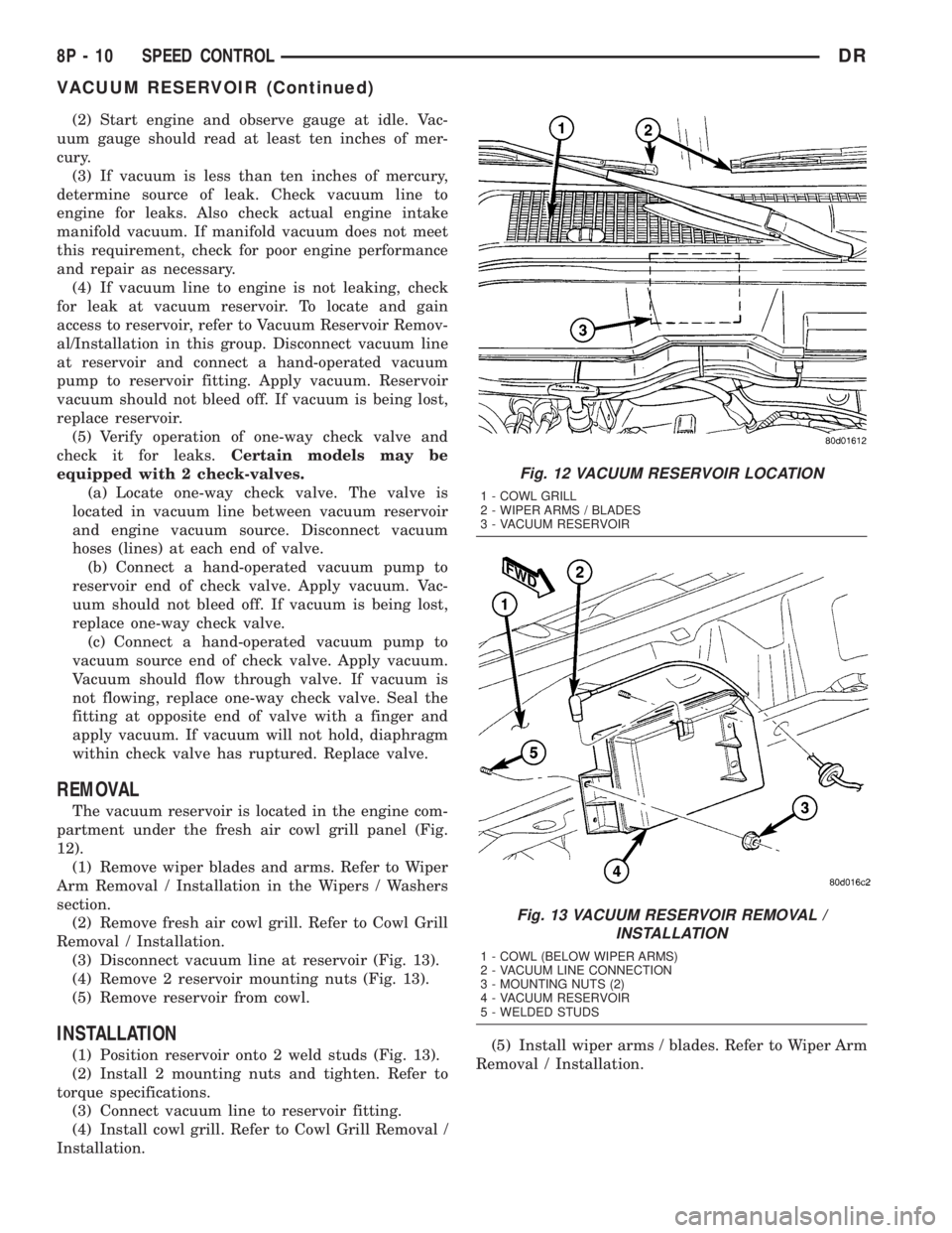
REMOVAL
The vacuum reservoir is located in the engine com-
partment under the fresh air cowl grill panel (Fig.
12).
(1) Remove wiper blades and arms. Refer to Wiper
Arm Removal / Installation in the Wipers / Washers
section.
(2) Remove fresh air cowl grill. Refer to Cowl Grill
Removal / Installation.
(3) Disconnect vacuum line at reservoir (Fig. 13).
(4) Remove 2 reservoir mounting nuts (Fig. 13).
(5) Remove reservoir from cowl.
INSTALLATION
(1) Position reservoir onto 2 weld studs (Fig. 13).
(2) Install 2 mounting nuts and tighten. Refer to
torque specifications.
(3) Connect vacuum line to reservoir fitting.
(4) Install cowl grill. Refer to Cowl Grill Removal /
Installation.(5) Install wiper arms / blades. Refer to Wiper Arm
Removal / Installation.
Fig. 12 VACUUM RESERVOIR LOCATION
1 - COWL GRILL
2 - WIPER ARMS / BLADES
3 - VACUUM RESERVOIR
Fig. 13 VACUUM RESERVOIR REMOVAL /
INSTALLATION
1 - COWL (BELOW WIPER ARMS)
2 - VACUUM LINE CONNECTION
3 - MOUNTING NUTS (2)
4 - VACUUM RESERVOIR
5 - WELDED STUDS
8P - 10 SPEED CONTROLDR
VACUUM RESERVOIR (Continued)
Page 720 of 2895
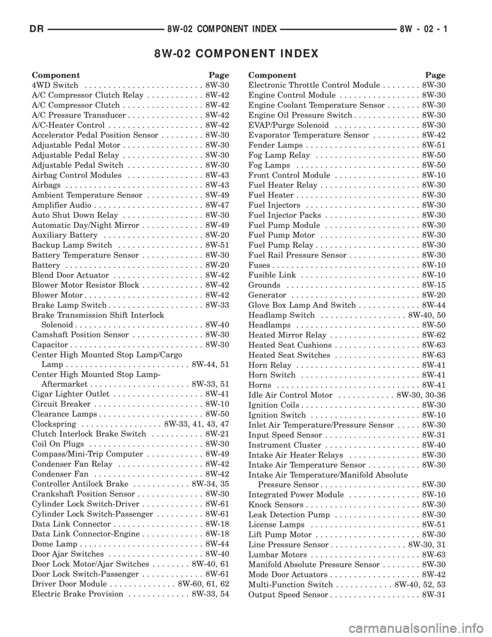
8W-02 COMPONENT INDEX
Component Page
4WD Switch......................... 8W-30
A/C Compressor Clutch Relay............ 8W-42
A/C Compressor Clutch................. 8W-42
A/C Pressure Transducer................ 8W-42
A/C-Heater Control.................... 8W-42
Accelerator Pedal Position Sensor......... 8W-30
Adjustable Pedal Motor................. 8W-30
Adjustable Pedal Relay................. 8W-30
Adjustable Pedal Switch................ 8W-30
Airbag Control Modules................ 8W-43
Airbags............................. 8W-43
Ambient Temperature Sensor............ 8W-49
Amplifier Audio....................... 8W-47
Auto Shut Down Relay................. 8W-30
Automatic Day/Night Mirror............. 8W-49
Auxiliary Battery..................... 8W-20
Backup Lamp Switch.................. 8W-51
Battery Temperature Sensor............. 8W-30
Battery............................. 8W-20
Blend Door Actuator................... 8W-42
Blower Motor Resistor Block............. 8W-42
Blower Motor......................... 8W-42
Brake Lamp Switch.................... 8W-33
Brake Transmission Shift Interlock
Solenoid........................... 8W-40
Camshaft Position Sensor............... 8W-30
Capacitor............................ 8W-30
Center High Mounted Stop Lamp/Cargo
Lamp.......................... 8W-44, 51
Center High Mounted Stop Lamp-
Aftermarket..................... 8W-33, 51
Cigar Lighter Outlet................... 8W-41
Circuit Breaker....................... 8W-10
Clearance Lamps...................... 8W-50
Clockspring................. 8W-33, 41, 43, 47
Clutch Interlock Brake Switch........... 8W-21
Coil On Plugs........................ 8W-30
Compass/Mini-Trip Computer............ 8W-49
Condenser Fan Relay.................. 8W-42
Condenser Fan....................... 8W-42
Controller Antilock Brake............ 8W-34, 35
Crankshaft Position Sensor.............. 8W-30
Cylinder Lock Switch-Driver............. 8W-61
Cylinder Lock Switch-Passenger.......... 8W-61
Data Link Connector................... 8W-18
Data Link Connector-Engine............. 8W-18
Dome Lamp.......................... 8W-44
Door Ajar Switches.................... 8W-40
Door Lock Motor/Ajar Switches........ 8W-40, 61
Door Lock Switch-Passenger............. 8W-61
Driver Door Module.............. 8W-60, 61, 62
Electric Brake Provision............. 8W-33, 54Component Page
Electronic Throttle Control Module........ 8W-30
Engine Control Module................. 8W-30
Engine Coolant Temperature Sensor....... 8W-30
Engine Oil Pressure Switch.............. 8W-30
EVAP/Purge Solenoid.................. 8W-30
Evaporator Temperature Sensor.......... 8W-42
Fender Lamps........................ 8W-51
Fog Lamp Relay...................... 8W-50
Fog Lamps.......................... 8W-50
Front Control Module.................. 8W-10
Fuel Heater Relay..................... 8W-30
Fuel Heater.......................... 8W-30
Fuel Injectors........................ 8W-30
Fuel Injector Packs.................... 8W-30
Fuel Pump Module.................... 8W-30
Fuel Pump Motor..................... 8W-30
Fuel Pump Relay...................... 8W-30
Fuel Rail Pressure Sensor............... 8W-30
Fuses............................... 8W-10
Fusible Link......................... 8W-10
Grounds............................ 8W-15
Generator........................... 8W-20
Glove Box Lamp And Switch............. 8W-44
Headlamp Switch.................. 8W-40, 50
Headlamps.......................... 8W-50
Heated Mirror Relay................... 8W-62
Heated Seat Cushions.................. 8W-63
Heated Seat Switches.................. 8W-63
Horn Relay.......................... 8W-41
Horn Switch......................... 8W-41
Horns.............................. 8W-41
Idle Air Control Motor............ 8W-30, 30-36
Ignition Coils......................... 8W-30
Ignition Switch....................... 8W-10
Inlet Air Temperature/Pressure Sensor..... 8W-30
Input Speed Sensor.................... 8W-31
Instrument Cluster.................... 8W-40
Intake Air Heater Relays............... 8W-30
Intake Air Temperature Sensor........... 8W-30
Intake Air Temperature/Manifold Absolute
Pressure Sensor..................... 8W-30
Integrated Power Module............... 8W-10
Knock Sensors........................ 8W-30
Leak Detection Pump.................. 8W-30
License Lamps....................... 8W-51
Lift Pump Motor...................... 8W-30
Line Pressure Sensor................ 8W-30, 31
Lumbar Motors....................... 8W-63
Manifold Absolute Pressure Sensor........ 8W-30
Mode Door Actuators................... 8W-42
Multi-Function Switch............ 8W-40, 52, 53
Output Speed Sensor................... 8W-31
DR8W-02 COMPONENT INDEX 8W - 02 - 1
Page 816 of 2895
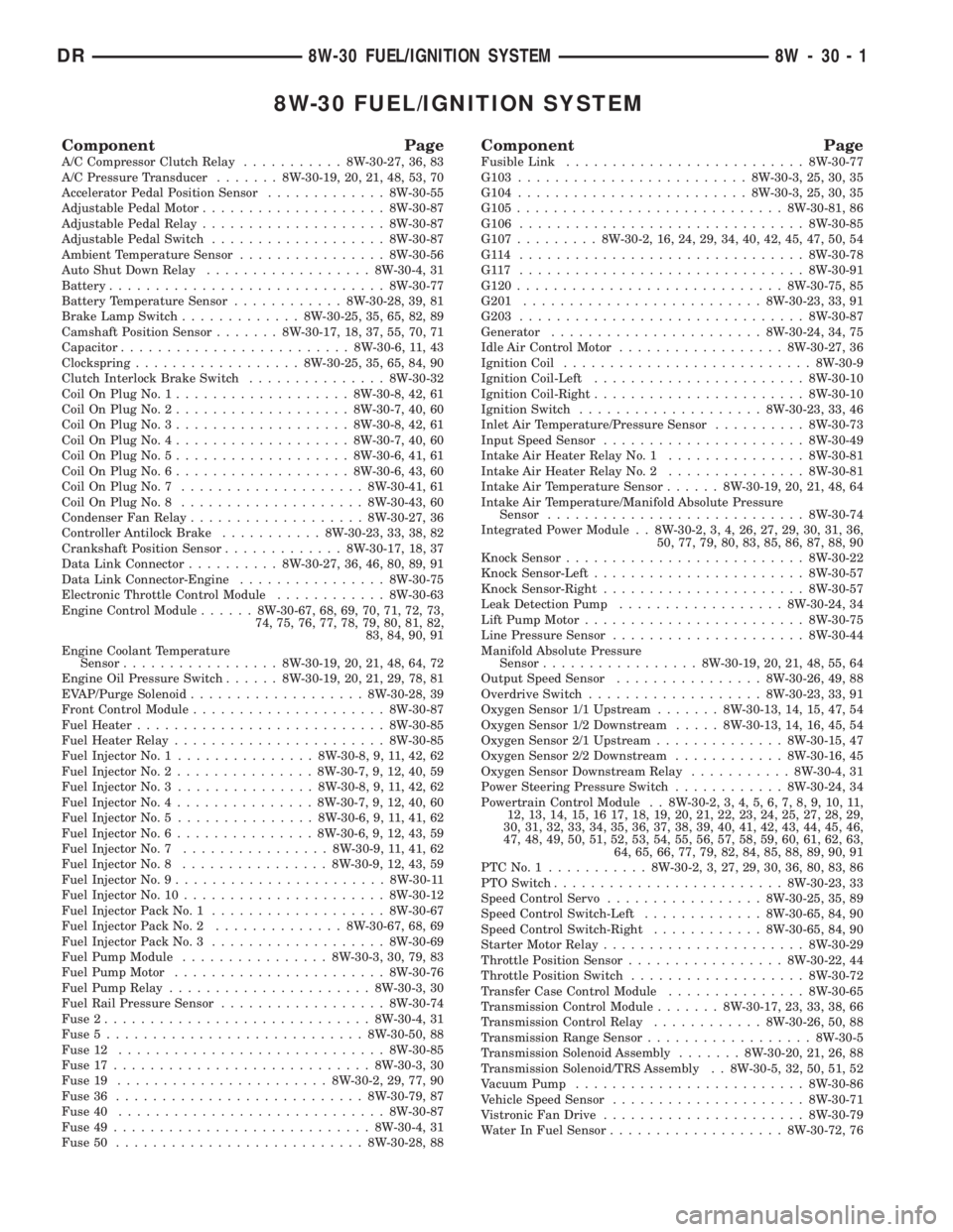
8W-30 FUEL/IGNITION SYSTEM
Component PageA/C Compressor Clutch Relay...........8W-30-27, 36, 83
A/C Pressure Transducer.......8W-30-19, 20, 21, 48, 53, 70
Accelerator Pedal Position Sensor.............8W-30-55
Adjustable Pedal Motor....................8W-30-87
Adjustable Pedal Relay....................8W-30-87
Adjustable Pedal Switch...................8W-30-87
Ambient Temperature Sensor................8W-30-56
Auto Shut Down Relay..................8W-30-4, 31
Battery..............................8W-30-77
Battery Temperature Sensor............8W-30-28, 39, 81
Brake Lamp Switch.............8W-30-25, 35, 65, 82, 89
Camshaft Position Sensor.......8W-30-17, 18, 37, 55, 70, 71
Capacitor.........................8W-30-6, 11, 43
Clockspring..................8W-30-25, 35, 65, 84, 90
Clutch Interlock Brake Switch...............8W-30-32
Coil On Plug No. 1...................8W-30-8, 42, 61
Coil On Plug No. 2...................8W-30-7, 40, 60
Coil On Plug No. 3...................8W-30-8, 42, 61
Coil On Plug No. 4...................8W-30-7, 40, 60
Coil On Plug No. 5...................8W-30-6, 41, 61
Coil On Plug No. 6...................8W-30-6, 43, 60
Coil On Plug No. 7....................8W-30-41, 61
Coil On Plug No. 8....................8W-30-43, 60
Condenser Fan Relay...................8W-30-27, 36
Controller Antilock Brake...........8W-30-23, 33, 38, 82
Crankshaft Position Sensor.............8W-30-17, 18, 37
Data Link Connector..........8W-30-27, 36, 46, 80, 89, 91
Data Link Connector-Engine................8W-30-75
Electronic Throttle Control Module............8W-30-63
Engine Control Module......8W-30-67, 68, 69, 70, 71, 72, 73,
74, 75, 76, 77, 78, 79, 80, 81, 82,
83, 84, 90, 91
Engine Coolant Temperature
Sensor.................8W-30-19, 20, 21, 48, 64, 72
Engine Oil Pressure Switch......8W-30-19, 20, 21, 29, 78, 81
EVAP/Purge Solenoid...................8W-30-28, 39
Front Control Module.....................8W-30-87
Fuel Heater...........................8W-30-85
Fuel Heater Relay.......................8W-30-85
Fuel Injector No. 1...............8W-30-8, 9, 11, 42, 62
Fuel Injector No. 2...............8W-30-7, 9, 12, 40, 59
Fuel Injector No. 3...............8W-30-8, 9, 11, 42, 62
Fuel Injector No. 4...............8W-30-7, 9, 12, 40, 60
Fuel Injector No. 5...............8W-30-6, 9, 11, 41, 62
Fuel Injector No. 6...............8W-30-6, 9, 12, 43, 59
Fuel Injector No. 7................8W-30-9, 11, 41, 62
Fuel Injector No. 8................8W-30-9, 12, 43, 59
Fuel Injector No. 9.......................8W-30-11
Fuel Injector No. 10......................8W-30-12
Fuel Injector Pack No. 1...................8W-30-67
Fuel Injector Pack No. 2..............8W-30-67, 68, 69
Fuel Injector Pack No. 3...................8W-30-69
Fuel Pump Module................8W-30-3, 30, 79, 83
Fuel Pump Motor.......................8W-30-76
Fuel Pump Relay......................8W-30-3, 30
Fuel Rail Pressure Sensor..................8W-30-74
Fuse 2.............................8W-30-4, 31
Fuse 5............................8W-30-50, 88
Fuse 12.............................8W-30-85
Fuse 17............................8W-30-3, 30
Fuse 19.......................8W-30-2, 29, 77, 90
Fuse 36...........................8W-30-79, 87
Fuse 40.............................8W-30-87
Fuse 49............................8W-30-4, 31
Fuse 50...........................8W-30-28, 88Component PageFusible Link..........................8W-30-77
G103.........................8W-30-3, 25, 30, 35
G104.........................8W-30-3, 25, 30, 35
G105.............................8W-30-81, 86
G106...............................8W-30-85
G107.........8W-30-2, 16, 24, 29, 34, 40, 42, 45, 47, 50, 54
G114 ...............................8W-30-78
G117 ...............................8W-30-91
G120.............................8W-30-75, 85
G201..........................8W-30-23, 33, 91
G203...............................8W-30-87
Generator.......................8W-30-24, 34, 75
Idle Air Control Motor..................8W-30-27, 36
Ignition Coil...........................8W-30-9
Ignition Coil-Left.......................8W-30-10
Ignition Coil-Right.......................8W-30-10
Ignition Switch....................8W-30-23, 33, 46
Inlet Air Temperature/Pressure Sensor..........8W-30-73
Input Speed Sensor......................8W-30-49
Intake Air Heater Relay No. 1...............8W-30-81
Intake Air Heater Relay No. 2...............8W-30-81
Intake Air Temperature Sensor......8W-30-19, 20, 21, 48, 64
Intake Air Temperature/Manifold Absolute Pressure
Sensor............................8W-30-74
Integrated Power Module . . 8W-30-2, 3, 4, 26, 27, 29, 30, 31, 36,
50, 77, 79, 80, 83, 85, 86, 87, 88, 90
Knock Sensor..........................8W-30-22
Knock Sensor-Left.......................8W-30-57
Knock Sensor-Right......................8W-30-57
Leak Detection Pump..................8W-30-24, 34
Lift Pump Motor........................8W-30-75
Line Pressure Sensor.....................8W-30-44
Manifold Absolute Pressure
Sensor.................8W-30-19, 20, 21, 48, 55, 64
Output Speed Sensor................8W-30-26, 49, 88
Overdrive Switch...................8W-30-23, 33, 91
Oxygen Sensor 1/1 Upstream.......8W-30-13, 14, 15, 47, 54
Oxygen Sensor 1/2 Downstream.....8W-30-13, 14, 16, 45, 54
Oxygen Sensor 2/1 Upstream..............8W-30-15, 47
Oxygen Sensor 2/2 Downstream............8W-30-16, 45
Oxygen Sensor Downstream Relay...........8W-30-4, 31
Power Steering Pressure Switch............8W-30-24, 34
Powertrain Control Module . . 8W-30-2, 3, 4, 5, 6, 7, 8, 9, 10, 11,
12, 13, 14, 15, 16 17, 18, 19, 20, 21, 22, 23, 24, 25, 27, 28, 29,
30, 31, 32, 33, 34, 35, 36, 37, 38, 39, 40, 41, 42, 43, 44, 45, 46,
47, 48, 49, 50, 51, 52, 53, 54, 55, 56, 57, 58, 59, 60, 61, 62, 63,
64, 65, 66, 77, 79, 82, 84, 85, 88, 89, 90, 91
PTCNo.1 ...........8W-30-2, 3, 27, 29, 30, 36, 80, 83, 86
PTO Switch.........................8W-30-23, 33
Speed Control Servo.................8W-30-25, 35, 89
Speed Control Switch-Left.............8W-30-65, 84, 90
Speed Control Switch-Right............8W-30-65, 84, 90
Starter Motor Relay......................8W-30-29
Throttle Position Sensor.................8W-30-22, 44
Throttle Position Switch...................8W-30-72
Transfer Case Control Module...............8W-30-65
Transmission Control Module.......8W-30-17, 23, 33, 38, 66
Transmission Control Relay............8W-30-26, 50, 88
Transmission Range Sensor..................8W-30-5
Transmission Solenoid Assembly.......8W-30-20, 21, 26, 88
Transmission Solenoid/TRS Assembly . . 8W-30-5, 32, 50, 51, 52
Vacuum Pump.........................8W-30-86
Vehicle Speed Sensor.....................8W-30-71
Vistronic Fan Drive......................8W-30-79
Water In Fuel Sensor...................8W-30-72, 76
DR8W-30 FUEL/IGNITION SYSTEM 8W - 30 - 1
Page 1154 of 2895
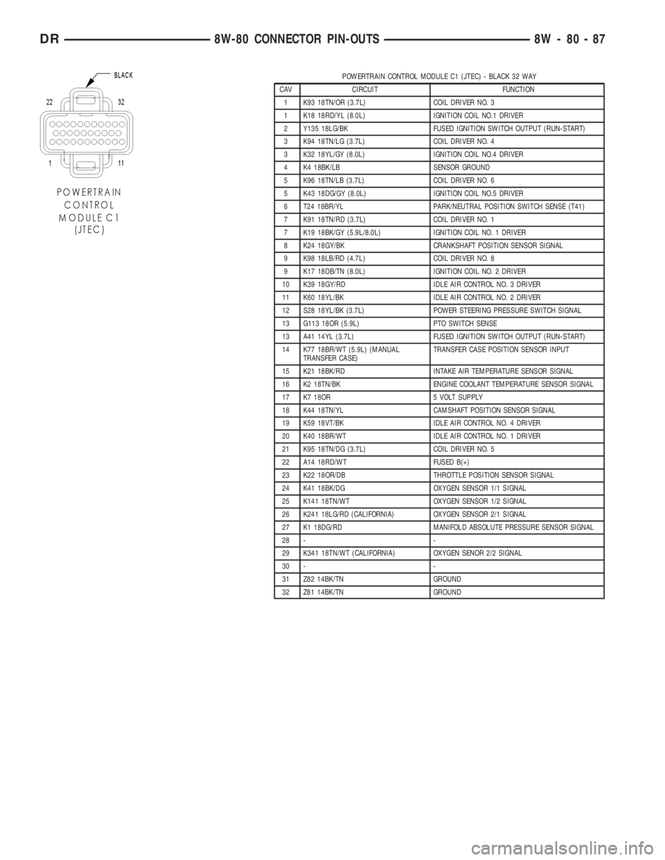
POWERTRAIN CONTROL MODULE C1 (JTEC) - BLACK 32 WAY
CAV CIRCUIT FUNCTION
1 K93 18TN/OR (3.7L) COIL DRIVER NO. 3
1 K18 18RD/YL (8.0L) IGNITION COIL NO.1 DRIVER
2 Y135 18LG/BK FUSED IGNITION SWITCH OUTPUT (RUN-START)
3 K94 18TN/LG (3.7L) COIL DRIVER NO. 4
3 K32 18YL/GY (8.0L) IGNITION COIL NO.4 DRIVER
4 K4 18BK/LB SENSOR GROUND
5 K96 18TN/LB (3.7L) COIL DRIVER NO. 6
5 K43 18DG/GY (8.0L) IGNITION COIL NO.5 DRIVER
6 T24 18BR/YL PARK/NEUTRAL POSITION SWITCH SENSE (T41)
7 K91 18TN/RD (3.7L) COIL DRIVER NO. 1
7 K19 18BK/GY (5.9L/8.0L) IGNITION COIL NO. 1 DRIVER
8 K24 18GY/BK CRANKSHAFT POSITION SENSOR SIGNAL
9 K98 18LB/RD (4.7L) COIL DRIVER NO. 8
9 K17 18DB/TN (8.0L) IGNITION COIL NO. 2 DRIVER
10 K39 18GY/RD IDLE AIR CONTROL NO. 3 DRIVER
11 K60 18YL/BK IDLE AIR CONTROL NO. 2 DRIVER
12 S28 18YL/BK (3.7L) POWER STEERING PRESSURE SWITCH SIGNAL
13 G113 18OR (5.9L) PTO SWITCH SENSE
13 A41 14YL (3.7L) FUSED IGNITION SWITCH OUTPUT (RUN-START)
14 K77 18BR/WT (5.9L) (MANUAL
TRANSFER CASE)TRANSFER CASE POSITION SENSOR INPUT
15 K21 18BK/RD INTAKE AIR TEMPERATURE SENSOR SIGNAL
16 K2 18TN/BK ENGINE COOLANT TEMPERATURE SENSOR SIGNAL
17 K7 18OR 5 VOLT SUPPLY
18 K44 18TN/YL CAMSHAFT POSITION SENSOR SIGNAL
19 K59 18VT/BK IDLE AIR CONTROL NO. 4 DRIVER
20 K40 18BR/WT IDLE AIR CONTROL NO. 1 DRIVER
21 K95 18TN/DG (3.7L) COIL DRIVER NO. 5
22 A14 18RD/WT FUSED B(+)
23 K22 18OR/DB THROTTLE POSITION SENSOR SIGNAL
24 K41 18BK/DG OXYGEN SENSOR 1/1 SIGNAL
25 K141 18TN/WT OXYGEN SENSOR 1/2 SIGNAL
26 K241 18LG/RD (CALIFORNIA) OXYGEN SENSOR 2/1 SIGNAL
27 K1 18DG/RD MANIFOLD ABSOLUTE PRESSURE SENSOR SIGNAL
28 - -
29 K341 18TN/WT (CALIFORNIA) OXYGEN SENOR 2/2 SIGNAL
30 - -
31 Z82 14BK/TN GROUND
32 Z81 14BK/TN GROUND
DR8W-80 CONNECTOR PIN-OUTS 8W - 80 - 87