fuel cap DODGE RAM 2003 Service Owner's Manual
[x] Cancel search | Manufacturer: DODGE, Model Year: 2003, Model line: RAM, Model: DODGE RAM 2003Pages: 2895, PDF Size: 83.15 MB
Page 1484 of 2895
(19) Install the distributor cap and wiring.
(20) Install the intake manifold (Refer to 9 -
ENGINE/MANIFOLDS/INTAKE MANIFOLD -
INSTALLATION).
(21) Using a new gasket, install throttle body
(Refer to 14 - FUEL SYSTEM/FUEL INJECTION/
THROTTLE BODY - INSTALLATION).
(22) Connect the throttle linkage (Refer to 14 -
FUEL SYSTEM/FUEL INJECTION/THROTTLE
CONTROL CABLE - INSTALLATION).
(23) Install the air cleaner resonator and duct
work..
(24) Install the generator and wire connections
(Refer to 8 - ELECTRICAL/CHARGING/GENERA-
TOR - INSTALLATION).
(25) Install a/c compressor and lines (Refer to 24 -
HEATING & AIR CONDITIONING/PLUMBING/A/C
COMPRESSOR - INSTALLATION).
(26) Install the accessory drive belt (Refer to 7 -
COOLING/ACCESSORY DRIVE/DRIVE BELTS -
INSTALLATION).
(27) Install upper radiator support crossmember.
(28) Install radiator (Refer to 7 - COOLING/EN-
GINE/RADIATOR - INSTALLATION).
(29) Connect the radiator lower hose.
(30) Connect the transmission oil cooler lines to
the radiator.
(31) Install the fan shroud.
(32) Install the fan (Refer to 7 - COOLING/EN-
GINE/RADIATOR FAN - INSTALLATION).
(33) Connect the radiator upper hose.
(34) Install the washer bottle.
(35) Install the transmission oil cooler (Refer to 7 -
COOLING/TRANSMISSION/TRANS COOLER -
INSTALLATION).
(36) Connect the transmission cooler lines.
(37) If equipped, install the condenser (Refer to 24
- HEATING & AIR CONDITIONING/PLUMBING/
A/C CONDENSER - INSTALLATION).
(38) Evacuate and charge the air conditioning sys-
tem, if equipped (Refer to 24 - HEATING & AIR
CONDITIONING/PLUMBING - STANDARD PRO-
CEDURE).
(39) Add engine oil to crankcase (Refer to LUBRI-
CATION & MAINTENANCE/FLUID TYPES - SPEC-
IFICATIONS).
(40) Fill cooling system (Refer to 7 - COOLING -
STANDARD PROCEDURE).
(41) Connect battery negative cable.
(42) Start engine and inspect for leaks.
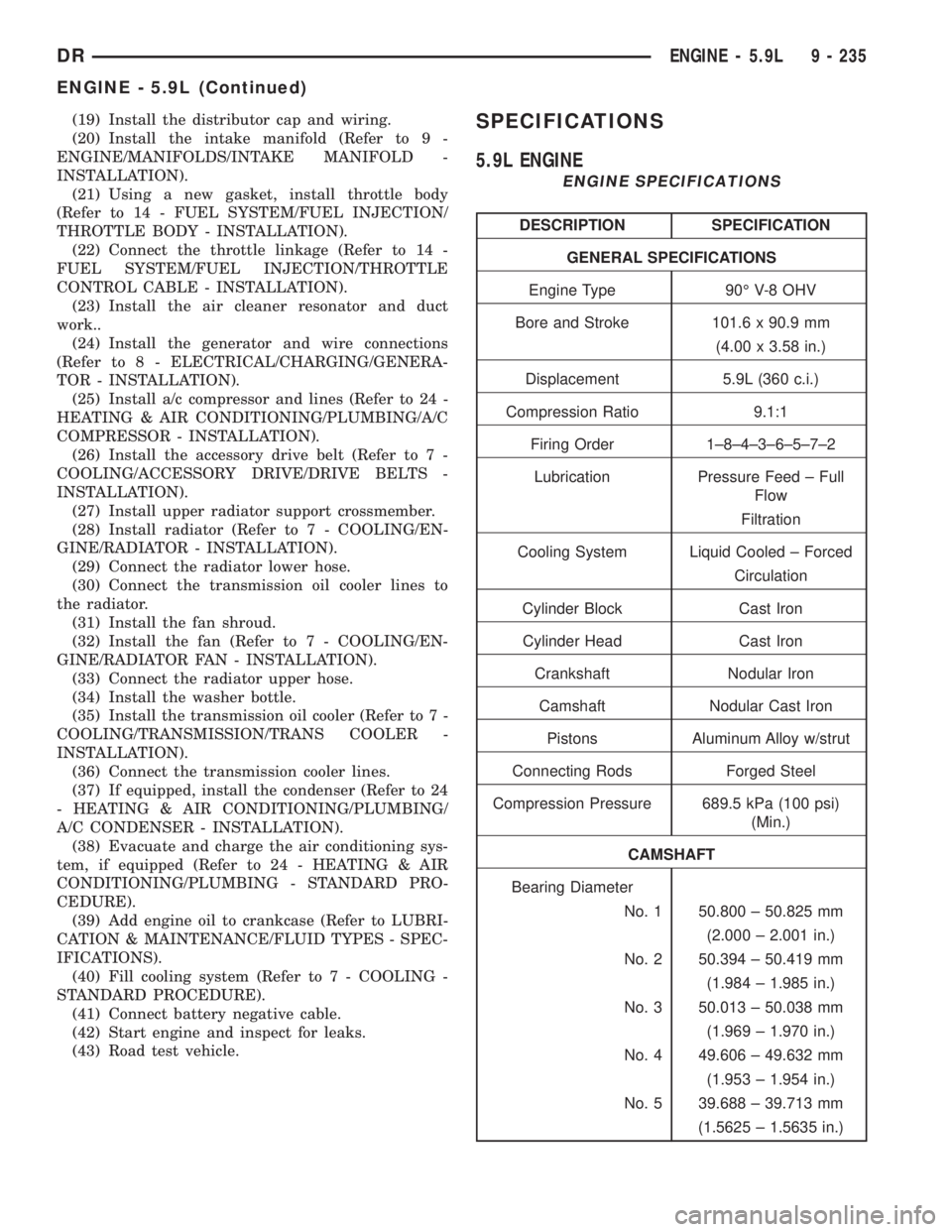
(43) Road test vehicle.SPECIFICATIONS
5.9L ENGINE
ENGINE SPECIFICATIONS
DESCRIPTION SPECIFICATION
GENERAL SPECIFICATIONS
Engine Type 90É V-8 OHV
Bore and Stroke 101.6 x 90.9 mm
(4.00 x 3.58 in.)
Displacement 5.9L (360 c.i.)
Compression Ratio 9.1:1
Firing Order 1±8±4±3±6±5±7±2
Lubrication Pressure Feed ± Full
Flow
Filtration
Cooling System Liquid Cooled ± Forced
Circulation
Cylinder Block Cast Iron
Cylinder Head Cast Iron
Crankshaft Nodular Iron
Camshaft Nodular Cast Iron
Pistons Aluminum Alloy w/strut
Connecting Rods Forged Steel
Compression Pressure 689.5 kPa (100 psi)
(Min.)
CAMSHAFT
Bearing Diameter
No. 1 50.800 ± 50.825 mm
(2.000 ± 2.001 in.)
No. 2 50.394 ± 50.419 mm
(1.984 ± 1.985 in.)
No. 3 50.013 ± 50.038 mm
(1.969 ± 1.970 in.)
No. 4 49.606 ± 49.632 mm
(1.953 ± 1.954 in.)
No. 5 39.688 ± 39.713 mm
(1.5625 ± 1.5635 in.)
DRENGINE - 5.9L 9 - 235
ENGINE - 5.9L (Continued)
Page 1492 of 2895
CYLINDER HEAD
DESCRIPTION
DESCRIPTIONÐCYLINDER HEAD
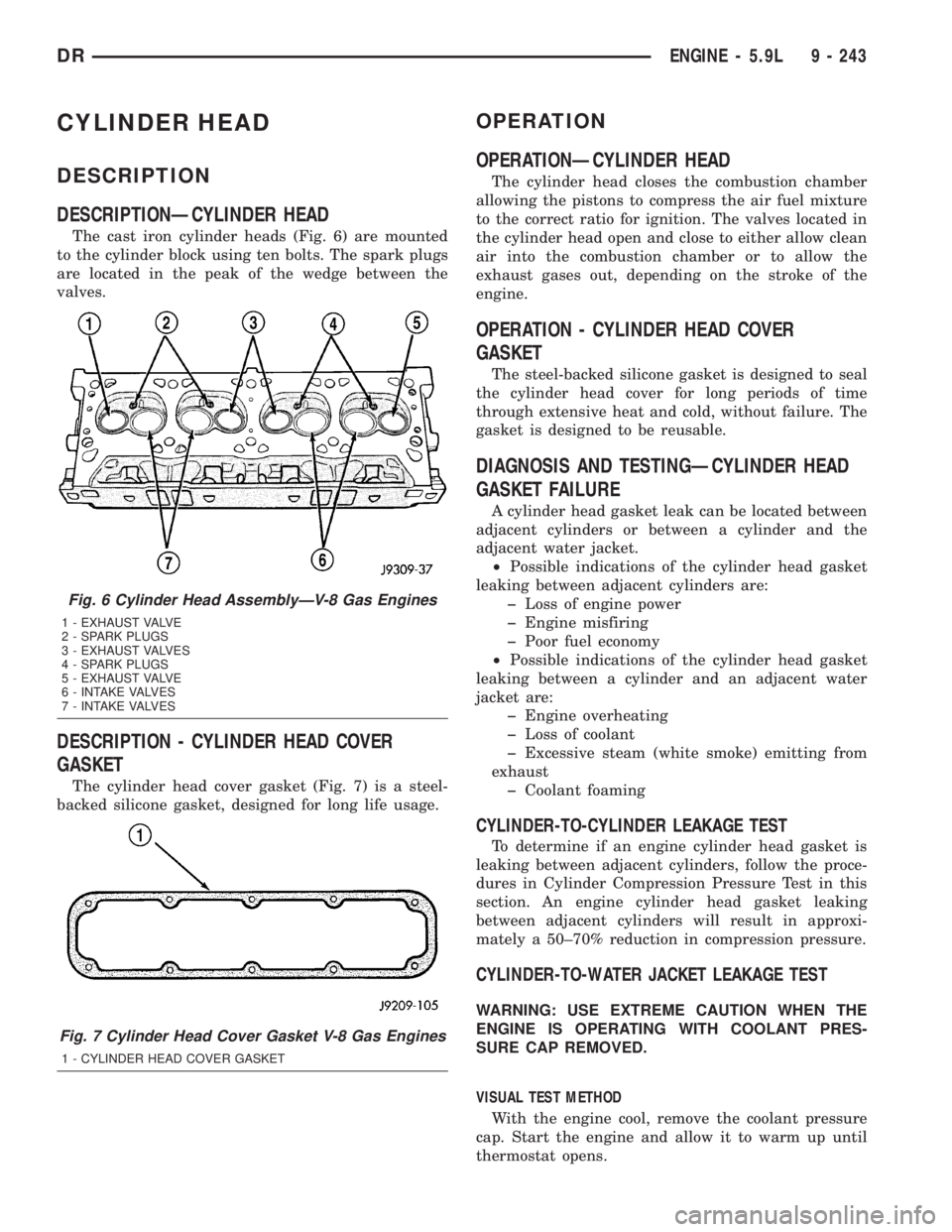
The cast iron cylinder heads (Fig. 6) are mounted
to the cylinder block using ten bolts. The spark plugs
are located in the peak of the wedge between the
valves.
DESCRIPTION - CYLINDER HEAD COVER
GASKET
The cylinder head cover gasket (Fig. 7) is a steel-
backed silicone gasket, designed for long life usage.
OPERATION
OPERATIONÐCYLINDER HEAD
The cylinder head closes the combustion chamber
allowing the pistons to compress the air fuel mixture
to the correct ratio for ignition. The valves located in
the cylinder head open and close to either allow clean
air into the combustion chamber or to allow the
exhaust gases out, depending on the stroke of the
engine.
OPERATION - CYLINDER HEAD COVER
GASKET
The steel-backed silicone gasket is designed to seal
the cylinder head cover for long periods of time
through extensive heat and cold, without failure. The
gasket is designed to be reusable.
DIAGNOSIS AND TESTINGÐCYLINDER HEAD
GASKET FAILURE
A cylinder head gasket leak can be located between
adjacent cylinders or between a cylinder and the
adjacent water jacket.
²Possible indications of the cylinder head gasket
leaking between adjacent cylinders are:
þ Loss of engine power
þ Engine misfiring
þ Poor fuel economy
²Possible indications of the cylinder head gasket
leaking between a cylinder and an adjacent water
jacket are:
þ Engine overheating
þ Loss of coolant
þ Excessive steam (white smoke) emitting from
exhaust
þ Coolant foaming
CYLINDER-TO-CYLINDER LEAKAGE TEST
To determine if an engine cylinder head gasket is
leaking between adjacent cylinders, follow the proce-
dures in Cylinder Compression Pressure Test in this
section. An engine cylinder head gasket leaking
between adjacent cylinders will result in approxi-
mately a 50±70% reduction in compression pressure.
CYLINDER-TO-WATER JACKET LEAKAGE TEST
WARNING: USE EXTREME CAUTION WHEN THE
ENGINE IS OPERATING WITH COOLANT PRES-
SURE CAP REMOVED.
VISUAL TEST METHOD
With the engine cool, remove the coolant pressure
cap. Start the engine and allow it to warm up until
thermostat opens.
Fig. 6 Cylinder Head AssemblyÐV-8 Gas Engines
1 - EXHAUST VALVE
2 - SPARK PLUGS
3 - EXHAUST VALVES
4 - SPARK PLUGS
5 - EXHAUST VALVE
6 - INTAKE VALVES
7 - INTAKE VALVES
Fig. 7 Cylinder Head Cover Gasket V-8 Gas Engines
1 - CYLINDER HEAD COVER GASKET
DRENGINE - 5.9L 9 - 243
Page 1493 of 2895
If a large combustion/compression pressure leak
exists, bubbles will be visible in the coolant.
COOLING SYSTEM TESTER METHOD
WARNING: WITH COOLING SYSTEM TESTER IN
PLACE, PRESSURE WILL BUILD UP FAST. EXCES-
SIVE PRESSURE BUILT UP, BY CONTINUOUS
ENGINE OPERATION, MUST BE RELEASED TO A
SAFE PRESSURE POINT. NEVER PERMIT PRES-
SURE TO EXCEED 138 kPa (20 psi).
Install Cooling System Tester 7700 or equivalent to
pressure cap neck. Start the engine and observe the
tester's pressure gauge. If gauge pulsates with every
power stroke of a cylinder a combustion pressure
leak is evident.
CHEMICAL TEST METHOD
Combustion leaks into the cooling system can also
be checked by using Bloc-Chek Kit C-3685-A or
equivalent. Perform test following the procedures
supplied with the tool kit.
REMOVAL
(1) Disconnect the battery negative cable.
(2) Drain cooling system (Refer to 7 - COOLING -
STANDARD PROCEDURE).
(3) Remove the air cleaner resonator and duct
work.
(4) Remove the intake manifold-to-generator
bracket support rod. Remove the generator.
(5) Remove closed crankcase ventilation system.
(6) Disconnect the evaporation control system.
(7) Perform the Fuel System Pressure Release pro-
cedure (Refer to 14 - FUEL SYSTEM/FUEL DELIV-
ERY - STANDARD PROCEDURE). Disconnect the
fuel supply line (Refer to 14 - FUEL SYSTEM/FUEL
DELIVERY/QUICK CONNECT FITTING - STAN-
DARD PROCEDURE).
(8) Disconnect accelerator linkage and if so
equipped, the speed control and transmission kick-
down cables.
(9) Remove distributor cap and wires.
(10) Disconnect the coil wires.
(11) Disconnect heat indicator sending unit wire.
(12) Disconnect heater hoses and bypass hose.
(13) Remove the master cylinder and booster
assembly. Refer to section 5 brakes.
(14) Remove cylinder head covers and gaskets
(Refer to 9 - ENGINE/CYLINDER HEAD/CYLIN-
DER HEAD COVER(S) - REMOVAL).
(15) Remove intake manifold (Refer to 9 -
ENGINE/MANIFOLDS/INTAKE MANIFOLD -
REMOVAL) and throttle body as an assembly. Dis-
card the flange side gaskets and the front and rear
cross-over gaskets.(16) Remove exhaust manifolds (Refer to 9 -
ENGINE/MANIFOLDS/EXHAUST MANIFOLD -
REMOVAL).
(17) Remove rocker arm assemblies and push rods.
Identify to ensure installation in original locations.
(18) Remove the head bolts from each cylinder
head and remove cylinder heads. Discard the cylin-
der head gasket.
(19) Remove spark plugs.
CLEANING
Clean all surfaces of cylinder block and cylinder
heads.
Clean cylinder block front and rear gasket surfaces
using a suitable solvent.
INSPECTION
Inspect all surfaces with a straightedge if there is
any reason to suspect leakage. If out-of-flatness
exceeds 0.00075mm/mm (0.0001in/in.) times the span
length in any direction, either replace head or lightly
machine the head surface.
FOR EXAMPLE:ÐA 305 mm (12 in.) span is
0.102 mm (0.004 in.) out-of-flat. The allowable out-of-
flat is 305 x 0.00075 (12 x 0.00075) equals 0.23 mm
(0.009 in.). This amount of out-of-flat is acceptable.
The cylinder head surface finish should be
1.78-3.00 microns (70-125 microinches).
Inspect push rods. Replace worn or bent rods.
INSTALLATION
(1) Clean all surfaces of cylinder block and cylin-
der heads.
(2) Clean cylinder block front and rear gasket sur-
faces using a suitable solvent.
(3) Position new cylinder head gaskets onto the
cylinder block.
(4) Position cylinder heads onto head gaskets and
cylinder block.
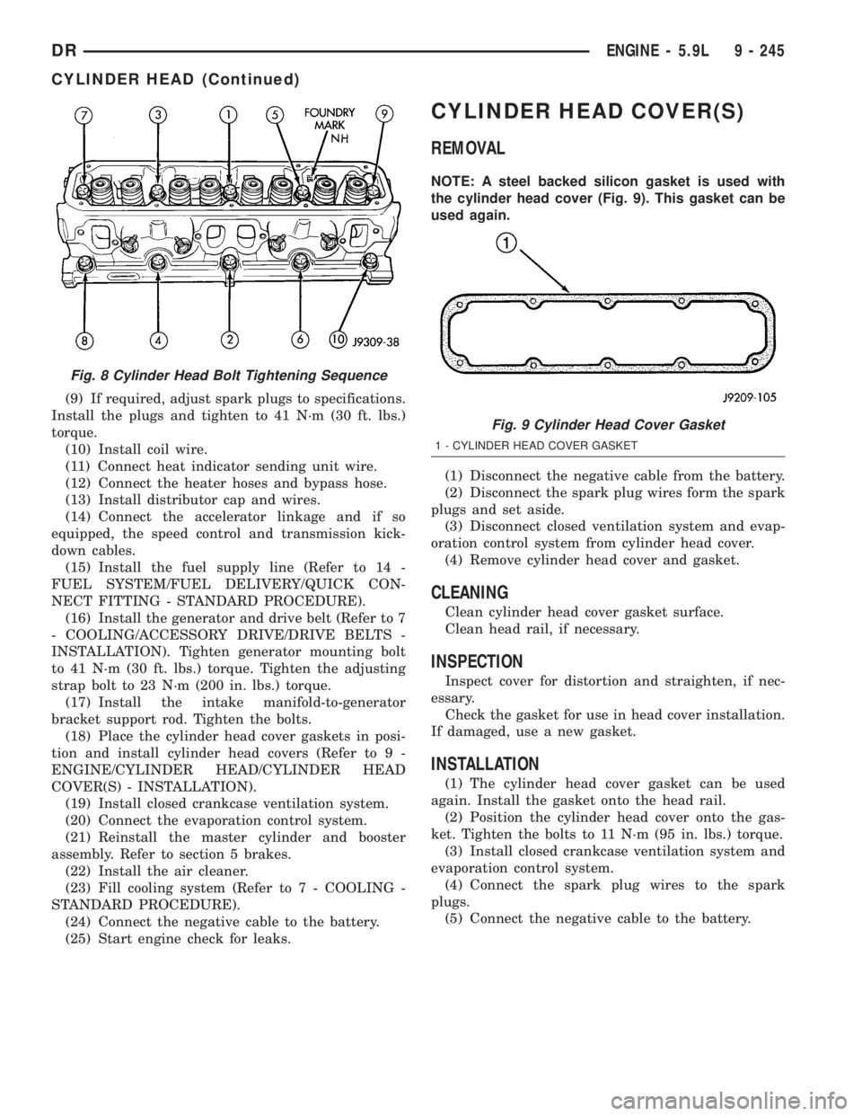
(5) Starting at top center, tighten all cylinder head
bolts, in sequence (Fig. 8).
CAUTION: When tightening the rocker arm bolts,
make sure the piston in that cylinder is NOT at
TDC. Contact between the valves and piston could
occur.
(6) Install push rods and rocker arm assemblies in
their original position. Tighten the bolts to 28 N´m
(21 ft. lbs.) torque.
(7) Install the intake manifold (Refer to 9 -
ENGINE/MANIFOLDS/INTAKE MANIFOLD -
INSTALLATION) and throttle body assembly.
(8) Install exhaust manifolds (Refer to 9 -
ENGINE/MANIFOLDS/EXHAUST MANIFOLD -
INSTALLATION).
9 - 244 ENGINE - 5.9LDR
CYLINDER HEAD (Continued)
Page 1494 of 2895
(9) If required, adjust spark plugs to specifications.
Install the plugs and tighten to 41 N´m (30 ft. lbs.)
torque.
(10) Install coil wire.
(11) Connect heat indicator sending unit wire.
(12) Connect the heater hoses and bypass hose.
(13) Install distributor cap and wires.
(14) Connect the accelerator linkage and if so
equipped, the speed control and transmission kick-
down cables.
(15) Install the fuel supply line (Refer to 14 -
FUEL SYSTEM/FUEL DELIVERY/QUICK CON-
NECT FITTING - STANDARD PROCEDURE).
(16) Install the generator and drive belt (Refer to 7
- COOLING/ACCESSORY DRIVE/DRIVE BELTS -
INSTALLATION). Tighten generator mounting bolt
to 41 N´m (30 ft. lbs.) torque. Tighten the adjusting
strap bolt to 23 N´m (200 in. lbs.) torque.
(17) Install the intake manifold-to-generator
bracket support rod. Tighten the bolts.
(18) Place the cylinder head cover gaskets in posi-
tion and install cylinder head covers (Refer to 9 -
ENGINE/CYLINDER HEAD/CYLINDER HEAD
COVER(S) - INSTALLATION).
(19) Install closed crankcase ventilation system.
(20) Connect the evaporation control system.
(21) Reinstall the master cylinder and booster
assembly. Refer to section 5 brakes.
(22) Install the air cleaner.
(23) Fill cooling system (Refer to 7 - COOLING -
STANDARD PROCEDURE).
(24) Connect the negative cable to the battery.
(25) Start engine check for leaks.
CYLINDER HEAD COVER(S)
REMOVAL
NOTE: A steel backed silicon gasket is used with
the cylinder head cover (Fig. 9). This gasket can be
used again.
(1) Disconnect the negative cable from the battery.
(2) Disconnect the spark plug wires form the spark
plugs and set aside.
(3) Disconnect closed ventilation system and evap-
oration control system from cylinder head cover.
(4) Remove cylinder head cover and gasket.
CLEANING
Clean cylinder head cover gasket surface.
Clean head rail, if necessary.
INSPECTION
Inspect cover for distortion and straighten, if nec-
essary.
Check the gasket for use in head cover installation.
If damaged, use a new gasket.
INSTALLATION
(1) The cylinder head cover gasket can be used
again. Install the gasket onto the head rail.
(2) Position the cylinder head cover onto the gas-
ket. Tighten the bolts to 11 N´m (95 in. lbs.) torque.
(3) Install closed crankcase ventilation system and
evaporation control system.
(4) Connect the spark plug wires to the spark
plugs.
(5) Connect the negative cable to the battery.
Fig. 8 Cylinder Head Bolt Tightening Sequence
Fig. 9 Cylinder Head Cover Gasket
1 - CYLINDER HEAD COVER GASKET
DRENGINE - 5.9L 9 - 245
CYLINDER HEAD (Continued)
Page 1523 of 2895
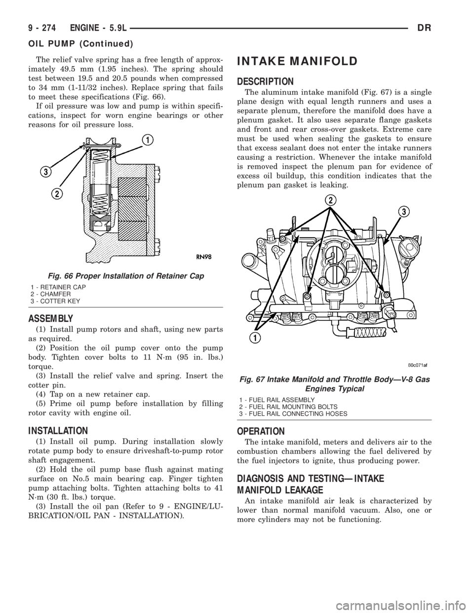
The relief valve spring has a free length of approx-
imately 49.5 mm (1.95 inches). The spring should
test between 19.5 and 20.5 pounds when compressed
to 34 mm (1-11/32 inches). Replace spring that fails
to meet these specifications (Fig. 66).
If oil pressure was low and pump is within specifi-
cations, inspect for worn engine bearings or other
reasons for oil pressure loss.
ASSEMBLY
(1) Install pump rotors and shaft, using new parts
as required.
(2) Position the oil pump cover onto the pump
body. Tighten cover bolts to 11 N´m (95 in. lbs.)
torque.
(3) Install the relief valve and spring. Insert the
cotter pin.
(4) Tap on a new retainer cap.
(5) Prime oil pump before installation by filling
rotor cavity with engine oil.
INSTALLATION
(1) Install oil pump. During installation slowly
rotate pump body to ensure driveshaft-to-pump rotor
shaft engagement.
(2) Hold the oil pump base flush against mating
surface on No.5 main bearing cap. Finger tighten
pump attaching bolts. Tighten attaching bolts to 41
N´m (30 ft. lbs.) torque.
(3) Install the oil pan (Refer to 9 - ENGINE/LU-
BRICATION/OIL PAN - INSTALLATION).
INTAKE MANIFOLD
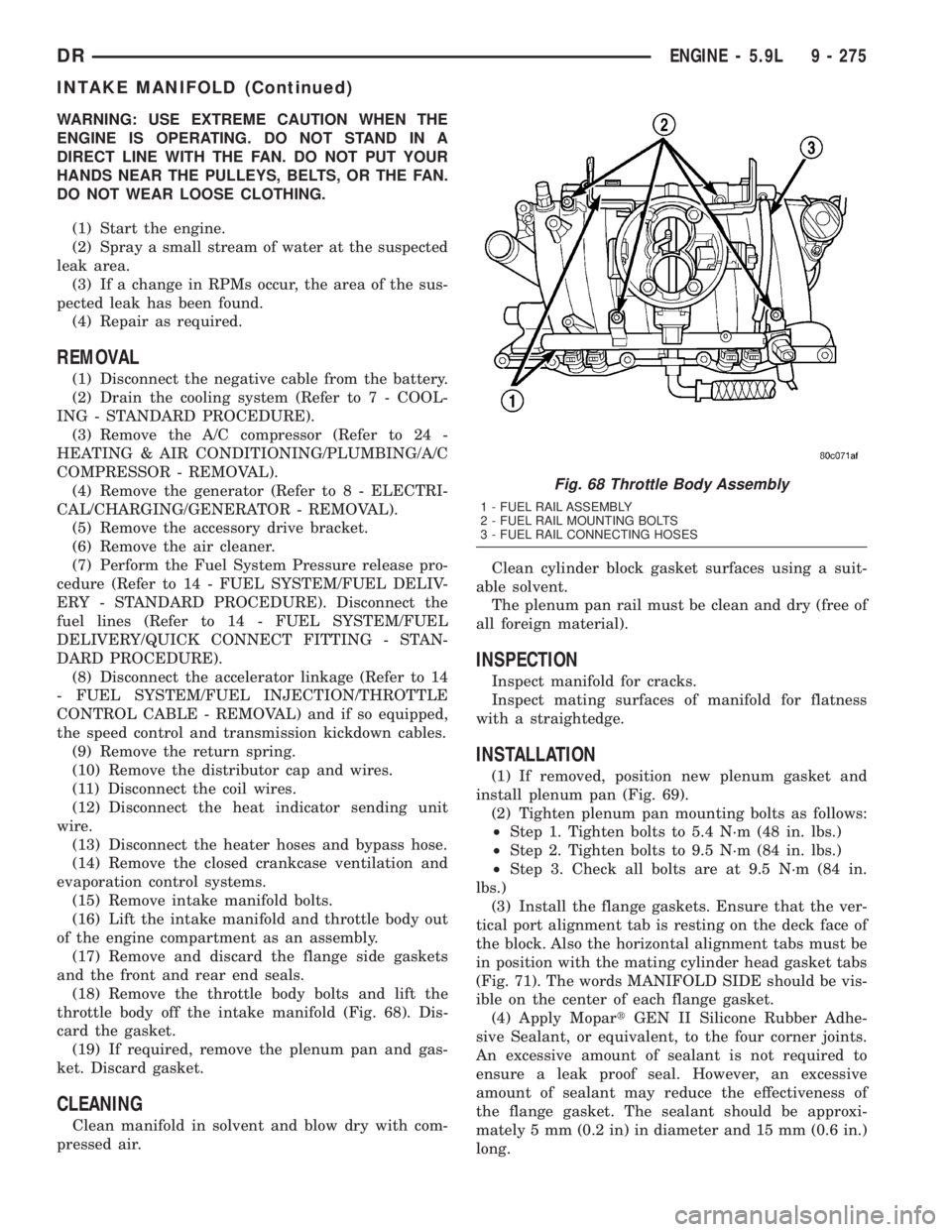
DESCRIPTION
The aluminum intake manifold (Fig. 67) is a single
plane design with equal length runners and uses a
separate plenum, therefore the manifold does have a
plenum gasket. It also uses separate flange gaskets
and front and rear cross-over gaskets. Extreme care
must be used when sealing the gaskets to ensure
that excess sealant does not enter the intake runners
causing a restriction. Whenever the intake manifold
is removed inspect the plenum pan for evidence of
excess oil buildup, this condition indicates that the
plenum pan gasket is leaking.
OPERATION
The intake manifold, meters and delivers air to the
combustion chambers allowing the fuel delivered by
the fuel injectors to ignite, thus producing power.
DIAGNOSIS AND TESTINGÐINTAKE
MANIFOLD LEAKAGE
An intake manifold air leak is characterized by
lower than normal manifold vacuum. Also, one or
more cylinders may not be functioning.
Fig. 66 Proper Installation of Retainer Cap
1 - RETAINER CAP
2 - CHAMFER
3 - COTTER KEY
Fig. 67 Intake Manifold and Throttle BodyÐV-8 Gas
Engines Typical
1 - FUEL RAIL ASSEMBLY
2 - FUEL RAIL MOUNTING BOLTS
3 - FUEL RAIL CONNECTING HOSES
9 - 274 ENGINE - 5.9LDR
OIL PUMP (Continued)
Page 1524 of 2895
WARNING: USE EXTREME CAUTION WHEN THE
ENGINE IS OPERATING. DO NOT STAND IN A
DIRECT LINE WITH THE FAN. DO NOT PUT YOUR
HANDS NEAR THE PULLEYS, BELTS, OR THE FAN.
DO NOT WEAR LOOSE CLOTHING.
(1) Start the engine.
(2) Spray a small stream of water at the suspected
leak area.
(3) If a change in RPMs occur, the area of the sus-
pected leak has been found.
(4) Repair as required.
REMOVAL
(1) Disconnect the negative cable from the battery.
(2) Drain the cooling system (Refer to 7 - COOL-
ING - STANDARD PROCEDURE).
(3) Remove the A/C compressor (Refer to 24 -
HEATING & AIR CONDITIONING/PLUMBING/A/C
COMPRESSOR - REMOVAL).
(4) Remove the generator (Refer to 8 - ELECTRI-
CAL/CHARGING/GENERATOR - REMOVAL).
(5) Remove the accessory drive bracket.
(6) Remove the air cleaner.
(7) Perform the Fuel System Pressure release pro-
cedure (Refer to 14 - FUEL SYSTEM/FUEL DELIV-
ERY - STANDARD PROCEDURE). Disconnect the
fuel lines (Refer to 14 - FUEL SYSTEM/FUEL
DELIVERY/QUICK CONNECT FITTING - STAN-
DARD PROCEDURE).
(8) Disconnect the accelerator linkage (Refer to 14
- FUEL SYSTEM/FUEL INJECTION/THROTTLE
CONTROL CABLE - REMOVAL) and if so equipped,
the speed control and transmission kickdown cables.
(9) Remove the return spring.
(10) Remove the distributor cap and wires.
(11) Disconnect the coil wires.
(12) Disconnect the heat indicator sending unit
wire.
(13) Disconnect the heater hoses and bypass hose.
(14) Remove the closed crankcase ventilation and
evaporation control systems.
(15) Remove intake manifold bolts.
(16) Lift the intake manifold and throttle body out
of the engine compartment as an assembly.
(17) Remove and discard the flange side gaskets
and the front and rear end seals.
(18) Remove the throttle body bolts and lift the
throttle body off the intake manifold (Fig. 68). Dis-
card the gasket.
(19) If required, remove the plenum pan and gas-
ket. Discard gasket.
CLEANING
Clean manifold in solvent and blow dry with com-
pressed air.Clean cylinder block gasket surfaces using a suit-
able solvent.
The plenum pan rail must be clean and dry (free of
all foreign material).
INSPECTION
Inspect manifold for cracks.
Inspect mating surfaces of manifold for flatness
with a straightedge.
INSTALLATION
(1) If removed, position new plenum gasket and
install plenum pan (Fig. 69).
(2) Tighten plenum pan mounting bolts as follows:
²Step 1. Tighten bolts to 5.4 N´m (48 in. lbs.)
²Step 2. Tighten bolts to 9.5 N´m (84 in. lbs.)
²Step 3. Check all bolts are at 9.5 N´m (84 in.
lbs.)
(3) Install the flange gaskets. Ensure that the ver-
tical port alignment tab is resting on the deck face of
the block. Also the horizontal alignment tabs must be
in position with the mating cylinder head gasket tabs
(Fig. 71). The words MANIFOLD SIDE should be vis-
ible on the center of each flange gasket.
(4) Apply MopartGEN II Silicone Rubber Adhe-
sive Sealant, or equivalent, to the four corner joints.
An excessive amount of sealant is not required to
ensure a leak proof seal. However, an excessive
amount of sealant may reduce the effectiveness of
the flange gasket. The sealant should be approxi-
mately 5 mm (0.2 in) in diameter and 15 mm (0.6 in.)
long.
Fig. 68 Throttle Body Assembly
1 - FUEL RAIL ASSEMBLY
2 - FUEL RAIL MOUNTING BOLTS
3 - FUEL RAIL CONNECTING HOSES
DRENGINE - 5.9L 9 - 275
INTAKE MANIFOLD (Continued)
Page 1525 of 2895
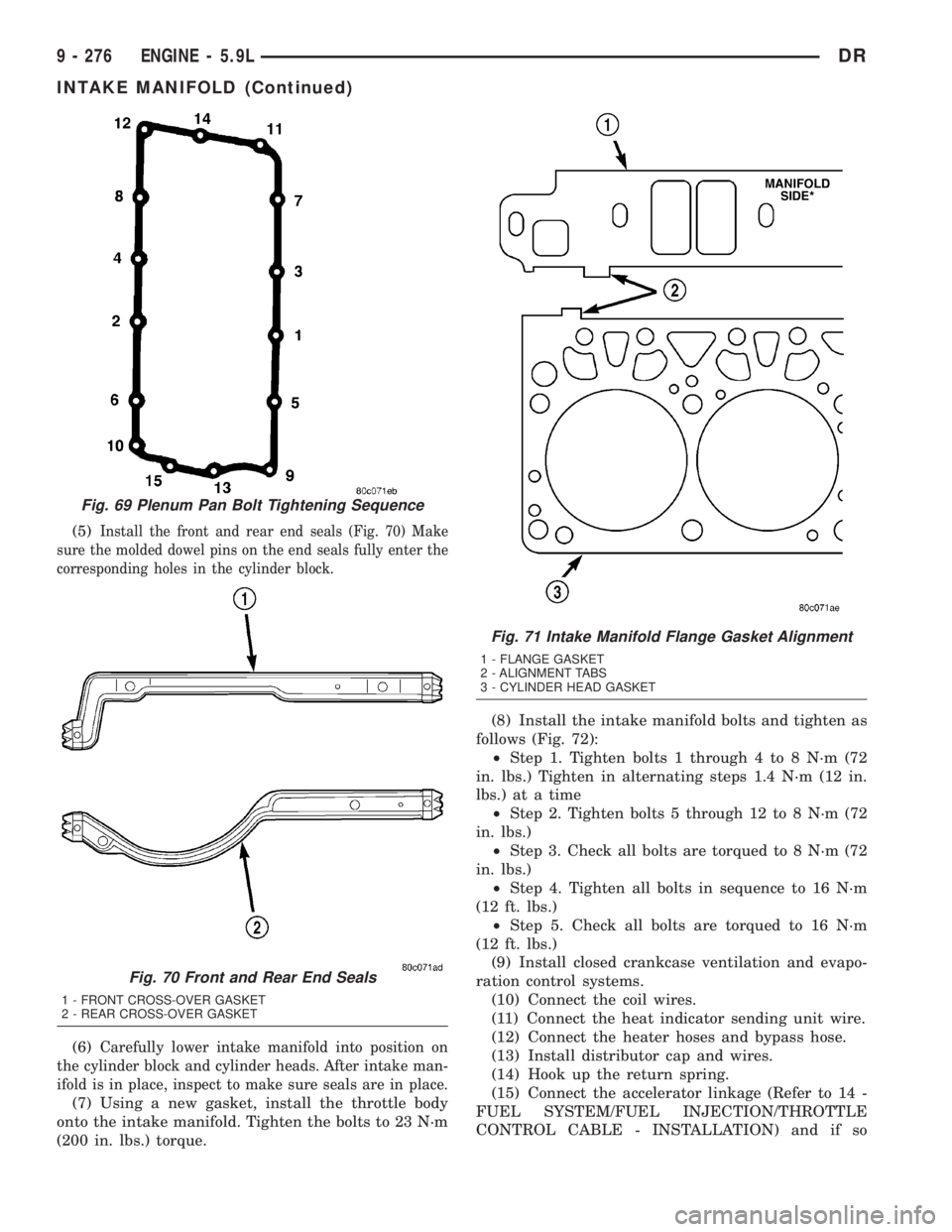
(5)Install the front and rear end seals (Fig. 70) Make
sure the molded dowel pins on the end seals fully enter the
corresponding holes in the cylinder block.
(6)Carefully lower intake manifold into position on
the cylinder block and cylinder heads. After intake man-
ifold is in place, inspect to make sure seals are in place.
(7) Using a new gasket, install the throttle body
onto the intake manifold. Tighten the bolts to 23 N´m
(200 in. lbs.) torque.(8) Install the intake manifold bolts and tighten as
follows (Fig. 72):
²Step 1. Tighten bolts 1 through 4 to 8 N´m (72
in. lbs.) Tighten in alternating steps 1.4 N´m (12 in.
lbs.) at a time
²Step 2. Tighten bolts 5 through 12 to 8 N´m (72
in. lbs.)
²Step 3. Check all bolts are torqued to 8 N´m (72
in. lbs.)
²Step 4. Tighten all bolts in sequence to 16 N´m
(12 ft. lbs.)
²Step 5. Check all bolts are torqued to 16 N´m
(12 ft. lbs.)
(9) Install closed crankcase ventilation and evapo-
ration control systems.
(10) Connect the coil wires.
(11) Connect the heat indicator sending unit wire.
(12) Connect the heater hoses and bypass hose.
(13) Install distributor cap and wires.
(14) Hook up the return spring.
(15) Connect the accelerator linkage (Refer to 14 -
FUEL SYSTEM/FUEL INJECTION/THROTTLE
CONTROL CABLE - INSTALLATION) and if so
Fig. 69 Plenum Pan Bolt Tightening Sequence
Fig. 70 Front and Rear End Seals
1 - FRONT CROSS-OVER GASKET
2 - REAR CROSS-OVER GASKET
Fig. 71 Intake Manifold Flange Gasket Alignment
1 - FLANGE GASKET
2 - ALIGNMENT TABS
3 - CYLINDER HEAD GASKET
9 - 276 ENGINE - 5.9LDR
INTAKE MANIFOLD (Continued)
Page 1532 of 2895
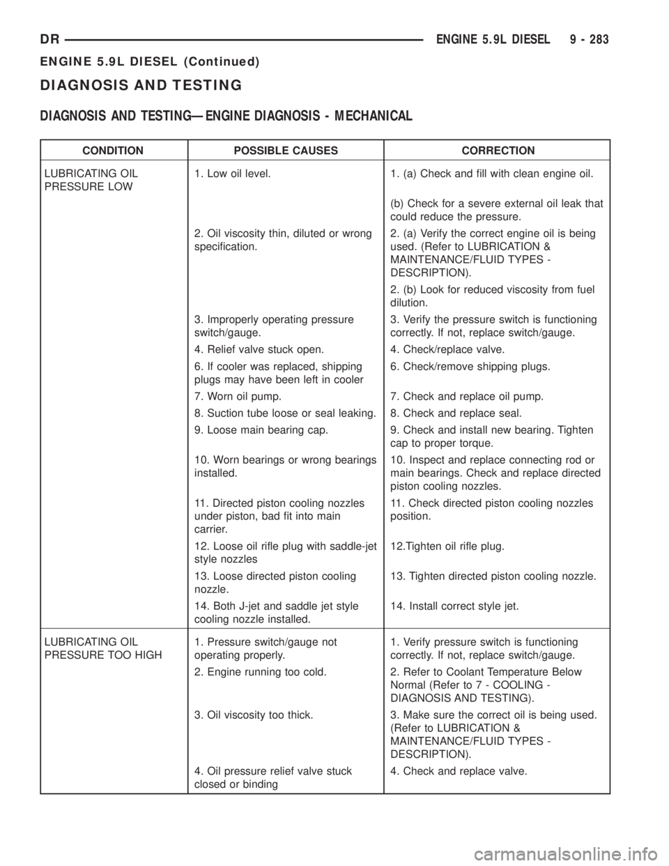
DIAGNOSIS AND TESTING
DIAGNOSIS AND TESTINGÐENGINE DIAGNOSIS - MECHANICAL
CONDITION POSSIBLE CAUSES CORRECTION
LUBRICATING OIL
PRESSURE LOW1. Low oil level. 1. (a) Check and fill with clean engine oil.
(b) Check for a severe external oil leak that
could reduce the pressure.
2. Oil viscosity thin, diluted or wrong
specification.2. (a) Verify the correct engine oil is being
used. (Refer to LUBRICATION &
MAINTENANCE/FLUID TYPES -
DESCRIPTION).
2. (b) Look for reduced viscosity from fuel
dilution.
3. Improperly operating pressure
switch/gauge.3. Verify the pressure switch is functioning
correctly. If not, replace switch/gauge.
4. Relief valve stuck open. 4. Check/replace valve.
6. If cooler was replaced, shipping
plugs may have been left in cooler6. Check/remove shipping plugs.
7. Worn oil pump. 7. Check and replace oil pump.
8. Suction tube loose or seal leaking. 8. Check and replace seal.
9. Loose main bearing cap. 9. Check and install new bearing. Tighten
cap to proper torque.
10. Worn bearings or wrong bearings
installed.10. Inspect and replace connecting rod or
main bearings. Check and replace directed
piston cooling nozzles.
11. Directed piston cooling nozzles
under piston, bad fit into main
carrier.11. Check directed piston cooling nozzles
position.
12. Loose oil rifle plug with saddle-jet
style nozzles12.Tighten oil rifle plug.
13. Loose directed piston cooling
nozzle.13. Tighten directed piston cooling nozzle.
14. Both J-jet and saddle jet style
cooling nozzle installed.14. Install correct style jet.
LUBRICATING OIL
PRESSURE TOO HIGH1. Pressure switch/gauge not
operating properly.1. Verify pressure switch is functioning
correctly. If not, replace switch/gauge.
2. Engine running too cold. 2. Refer to Coolant Temperature Below
Normal (Refer to 7 - COOLING -
DIAGNOSIS AND TESTING).
3. Oil viscosity too thick. 3. Make sure the correct oil is being used.
(Refer to LUBRICATION &
MAINTENANCE/FLUID TYPES -
DESCRIPTION).
4. Oil pressure relief valve stuck
closed or binding4. Check and replace valve.
DRENGINE 5.9L DIESEL 9 - 283
ENGINE 5.9L DIESEL (Continued)
Page 1537 of 2895
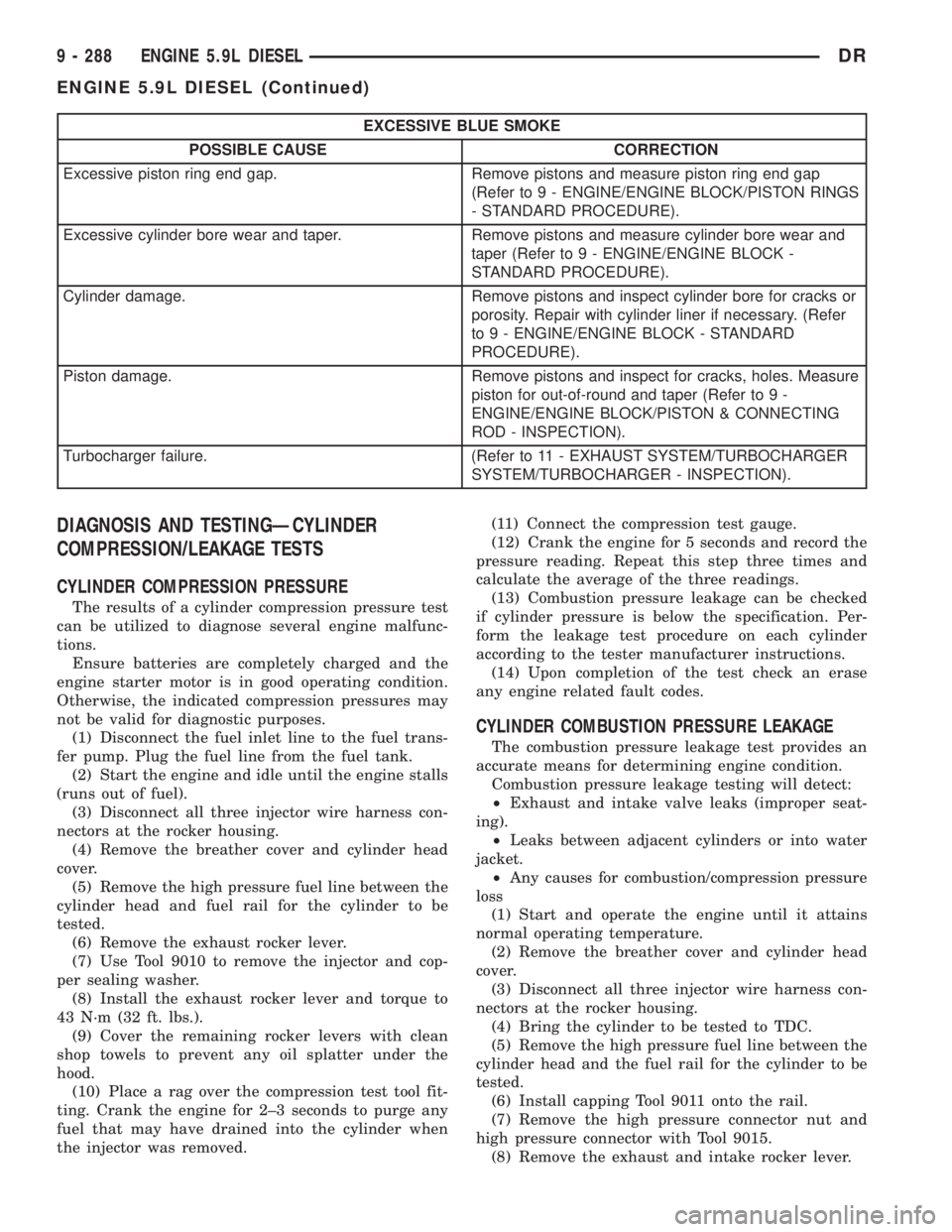
EXCESSIVE BLUE SMOKE
POSSIBLE CAUSE CORRECTION
Excessive piston ring end gap. Remove pistons and measure piston ring end gap
(Refer to 9 - ENGINE/ENGINE BLOCK/PISTON RINGS
- STANDARD PROCEDURE).
Excessive cylinder bore wear and taper. Remove pistons and measure cylinder bore wear and
taper (Refer to 9 - ENGINE/ENGINE BLOCK -
STANDARD PROCEDURE).
Cylinder damage. Remove pistons and inspect cylinder bore for cracks or
porosity. Repair with cylinder liner if necessary. (Refer
to 9 - ENGINE/ENGINE BLOCK - STANDARD
PROCEDURE).
Piston damage. Remove pistons and inspect for cracks, holes. Measure
piston for out-of-round and taper (Refer to 9 -
ENGINE/ENGINE BLOCK/PISTON & CONNECTING
ROD - INSPECTION).
Turbocharger failure. (Refer to 11 - EXHAUST SYSTEM/TURBOCHARGER
SYSTEM/TURBOCHARGER - INSPECTION).
DIAGNOSIS AND TESTINGÐCYLINDER
COMPRESSION/LEAKAGE TESTS
CYLINDER COMPRESSION PRESSURE
The results of a cylinder compression pressure test
can be utilized to diagnose several engine malfunc-
tions.
Ensure batteries are completely charged and the
engine starter motor is in good operating condition.
Otherwise, the indicated compression pressures may
not be valid for diagnostic purposes.
(1) Disconnect the fuel inlet line to the fuel trans-
fer pump. Plug the fuel line from the fuel tank.
(2) Start the engine and idle until the engine stalls
(runs out of fuel).
(3) Disconnect all three injector wire harness con-
nectors at the rocker housing.
(4) Remove the breather cover and cylinder head
cover.
(5) Remove the high pressure fuel line between the
cylinder head and fuel rail for the cylinder to be
tested.
(6) Remove the exhaust rocker lever.
(7) Use Tool 9010 to remove the injector and cop-
per sealing washer.
(8) Install the exhaust rocker lever and torque to
43 N´m (32 ft. lbs.).
(9) Cover the remaining rocker levers with clean
shop towels to prevent any oil splatter under the
hood.
(10) Place a rag over the compression test tool fit-
ting. Crank the engine for 2±3 seconds to purge any
fuel that may have drained into the cylinder when
the injector was removed.(11) Connect the compression test gauge.
(12) Crank the engine for 5 seconds and record the
pressure reading. Repeat this step three times and
calculate the average of the three readings.
(13) Combustion pressure leakage can be checked
if cylinder pressure is below the specification. Per-
form the leakage test procedure on each cylinder
according to the tester manufacturer instructions.
(14) Upon completion of the test check an erase
any engine related fault codes.
CYLINDER COMBUSTION PRESSURE LEAKAGE
The combustion pressure leakage test provides an
accurate means for determining engine condition.
Combustion pressure leakage testing will detect:
²Exhaust and intake valve leaks (improper seat-
ing).
²Leaks between adjacent cylinders or into water
jacket.
²Any causes for combustion/compression pressure
loss
(1) Start and operate the engine until it attains
normal operating temperature.
(2) Remove the breather cover and cylinder head
cover.
(3) Disconnect all three injector wire harness con-
nectors at the rocker housing.
(4) Bring the cylinder to be tested to TDC.
(5) Remove the high pressure fuel line between the
cylinder head and the fuel rail for the cylinder to be
tested.
(6) Install capping Tool 9011 onto the rail.
(7) Remove the high pressure connector nut and
high pressure connector with Tool 9015.
(8) Remove the exhaust and intake rocker lever.
9 - 288 ENGINE 5.9L DIESELDR
ENGINE 5.9L DIESEL (Continued)
Page 1540 of 2895
(35) Remove the passenger battery ground cable
from the engine block. Remove the driver side bat-
tery ground cable from the engine block.
(36) Remove power steering pump from engine by
removing 3 bolts.
(37) Remove accelerator linkage cover.
(38)
Disconnect cables from APPS if early model build
(39) If late model build,
(40) Disconnect the ECM power connector.
(41) Disconnect the ECM ground wire from the
hydroform screw.
(42) Disconnect the fuel supply and return hoses.
(43) Remove the cylinder head cover. (Refer to 9 -
ENGINE/CYLINDER HEAD/CYLINDER HEAD
COVER(S) - REMOVAL).
(44) Disconnect the 3 injector harness connectors
at the rocker housing. Disconnect the wire harnesses
from the injectors.
(45) Remove the rear engine lift bracket.
(46) Remove cylinder #4, #5, and #6 intake and
exhaust rocker arms, pedestals, and push tubes. Note
the original location for re-assembly.
(47) Loosen #6 fuel line shield bolts and rotate
shield out of the way.
(48)
Remove cylinder #5 and #6 high pressure fuel
lines. Remove the fuel connector tube nut and fuel con-
nector tube. 46. Remove cylinder #5 and #6 fuel injector.
(49) Remove rocker housing.
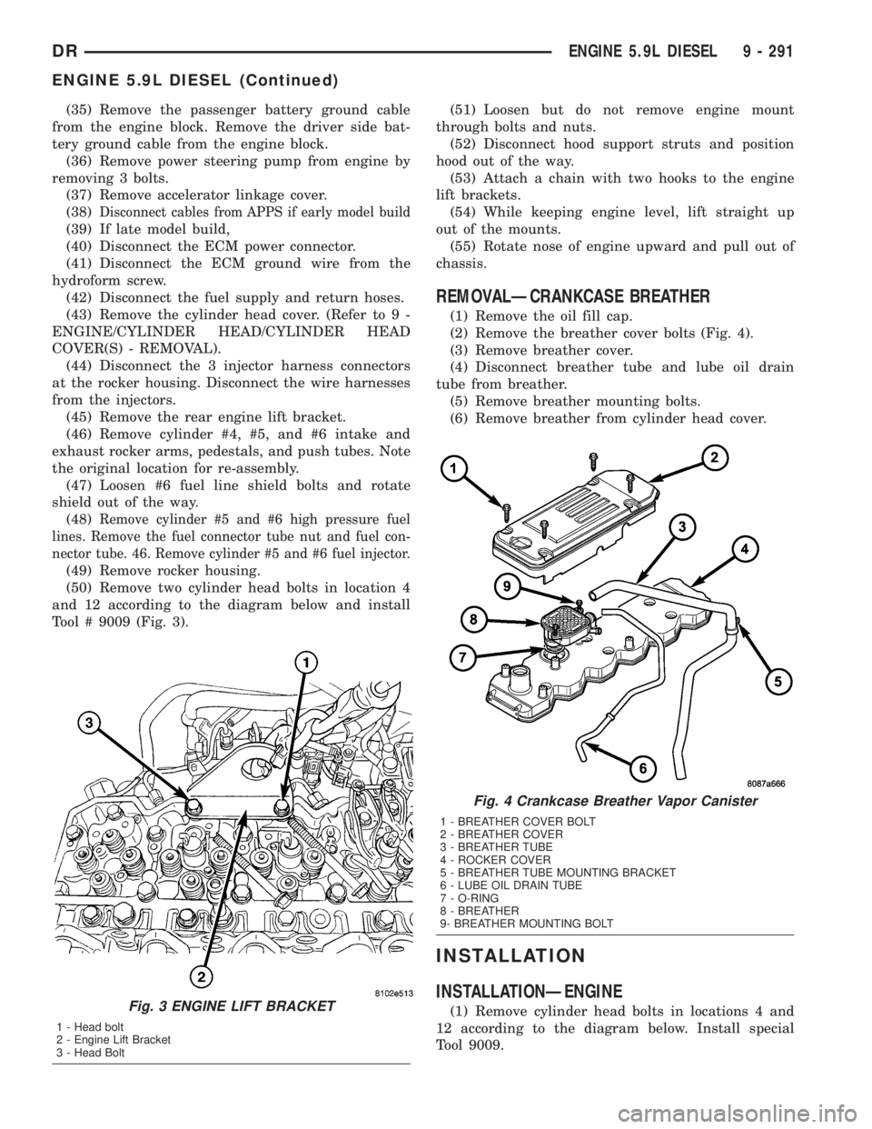
(50) Remove two cylinder head bolts in location 4
and 12 according to the diagram below and install
Tool # 9009 (Fig. 3).(51) Loosen but do not remove engine mount
through bolts and nuts.
(52) Disconnect hood support struts and position
hood out of the way.
(53) Attach a chain with two hooks to the engine
lift brackets.
(54) While keeping engine level, lift straight up
out of the mounts.
(55) Rotate nose of engine upward and pull out of
chassis.
REMOVALÐCRANKCASE BREATHER
(1) Remove the oil fill cap.
(2) Remove the breather cover bolts (Fig. 4).
(3) Remove breather cover.
(4) Disconnect breather tube and lube oil drain
tube from breather.
(5) Remove breather mounting bolts.
(6) Remove breather from cylinder head cover.
INSTALLATION
INSTALLATIONÐENGINE
(1) Remove cylinder head bolts in locations 4 and
12 according to the diagram below. Install special
Tool 9009.Fig. 3 ENGINE LIFT BRACKET
1 - Head bolt
2 - Engine Lift Bracket
3 - Head Bolt
Fig. 4 Crankcase Breather Vapor Canister
1 - BREATHER COVER BOLT
2 - BREATHER COVER
3 - BREATHER TUBE
4 - ROCKER COVER
5 - BREATHER TUBE MOUNTING BRACKET
6 - LUBE OIL DRAIN TUBE
7 - O-RING
8 - BREATHER
9- BREATHER MOUNTING BOLT
DRENGINE 5.9L DIESEL 9 - 291
ENGINE 5.9L DIESEL (Continued)