glove box DODGE RAM 2003 Service Owner's Manual
[x] Cancel search | Manufacturer: DODGE, Model Year: 2003, Model line: RAM, Model: DODGE RAM 2003Pages: 2895, PDF Size: 83.15 MB
Page 605 of 2895
²Clockspring- The clockspring is located near
the top of the steering column, directly beneath the
steering wheel.
²Driver Airbag- The driver airbag is located in
the center of the steering wheel, beneath the driver
airbag trim cover.
²Driver Knee Blocker- The driver knee blocker
is a structural unit secured to the back side of and
integral to the instrument panel steering column
opening cover.
²Passenger Airbag- The passenger airbag is
located on the instrument panel, beneath the passen-
ger airbag door on the instrument panel above the
glove box on the passenger side of the vehicle.
²Passenger Airbag On/Off Switch- Standard
cab models without a rear seat are equipped with a
passenger airbag on/off switch, which is located on
the right side of the instrument panel center bezel.
²Passenger Knee Blocker- The passenger knee
blocker is a structural reinforcement that is integral
to and concealed within the glove box door.
²Seat Belt Tensioner- The seat belt tensioner
is integral to the front outboard seat belt retractor
units on vehicles equipped with dual front airbags.
²Side Impact Airbag Control Module-Two
Side Impact Airbag Control Modules (SIACM) are
used on vehicles with the optional side curtain air-
bags, one left side and one right side. One SIACM is
located behind the B-pillar trim above the outboard
front seat belt retractor within each B-pillar.
²Side Curtain Airbag- In vehicles equipped
with this option, a side curtain airbag is located on
each inside roof side rail above the headliner, and
extends from the A-pillar to the B-pillar on standard
cab models, and from the A-pillar to the C-pillar on
quad cab models.
The ACM, both SIACMs, and the EMIC each con-
tain a central processing unit and programming that
allow them to communicate with each other usingthe Programmable Communications Interface (PCI)
data bus network. This method of communication is
used by the ACM for control of the airbag indicator
on all models equipped with dual front airbags.
(Refer to 8 - ELECTRICAL/ELECTRONIC CON-
TROL MODULES/COMMUNICATION - DESCRIP-
TION).
Hard wired circuitry connects the supplemental
restraint system components to each other through
the electrical system of the vehicle. These hard wired
circuits are integral to several wire harnesses, which
are routed throughout the vehicle and retained by
many different methods. These circuits may be con-
nected to each other, to the vehicle electrical system,
and to the supplemental restraint system compo-
nents through the use of a combination of soldered
splices, splice block connectors, and many different
types of wire harness terminal connectors and insu-
lators. Refer to the appropriate wiring information.
The wiring information includes wiring diagrams,
proper wire and connector repair procedures, further
details on wire harness routing and retention, as well
as pin-out and location views for the various wire
harness connectors, splices and grounds.
OPERATION
ACTIVE RESTRAINTS
The primary passenger restraints in this or any
other vehicle are the standard equipment factory-in-
stalled seat belts and child restraint anchors. Seat
belts and child restraint anchors are referred to as
an active restraint because the vehicle occupants are
required to physically fasten and properly adjust
these restraints in order to benefit from them. See
the owner's manual in the vehicle glove box for more
information on the features, use and operation of all
of the factory-installed active restraints.
PASSIVE RESTRAINTS
The passive restraints are referred to as a supple-
mental restraint system because they were designed
and are intended to enhance the protection for the
occupants of the vehicleonlywhen used in conjunc-
tion with the seat belts. They are referred to as pas-
sive restraints because the vehicle occupants are not
required to do anything to make them operate; how-
ever, the vehicle occupants must be wearing their
seat belts in order to obtain the maximum safety
benefit from the factory-installed supplemental
restraint system.
The supplemental restraint system electrical cir-
cuits are continuously monitored and controlled by a
microprocessor and software contained within the
Airbag Control Module (ACM) and, on vehicles
equipped with the side curtain airbags, both Side
Fig. 2 SRS Logo
8O - 4 RESTRAINTSDR
RESTRAINTS (Continued)
Page 606 of 2895
Impact Airbag Control Modules (SIACM). An airbag
indicator in the ElectroMechanical Instrument Clus-
ter (EMIC) illuminates for about six seconds as a
bulb test each time the ignition switch is turned to
the On or Start positions. Following the bulb test,
the airbag indicator is turned on or off by the ACM
to indicate the status of the supplemental restraint
system. If the airbag indicator comes on at any time
other than during the bulb test, it indicates that
there is a problem in the supplemental restraint sys-
tem electrical circuits. Such a problem may cause air-
bags not to deploy when required, or to deploy when
not required.
Deployment of the supplemental restraints
depends upon the angle and severity of an impact.
Deployment is not based upon vehicle speed; rather,
deployment is based upon the rate of deceleration as
measured by the forces of gravity (G force) upon the
impact sensors. When an impact is severe enough,
the microprocessor in the ACM or the SIACM signals
the inflator of the appropriate airbag units to deploy
their airbag cushions. The outboard front seat belt
tensioners are provided with a deployment signal by
the ACM in conjunction with the driver and passen-
ger airbags. During a frontal vehicle impact, the
knee blockers work in concert with properly fastened
and adjusted seat belts to restrain both the driver
and the front seat passenger in the proper position
for an airbag deployment. The knee blockers also
absorb and distribute the crash energy from the
driver and the front seat passenger to the structure
of the instrument panel. The seat belt tensioner
removes the slack from the outboard front seat belts
to provide further assurance that the driver and
front seat passenger are properly positioned and
restrained for an airbag deployment.
Typically, the vehicle occupants recall more about
the events preceding and following a collision than
they do of an airbag deployment itself. This is
because the airbag deployment and deflation occur so
rapidly. In a typical 48 kilometer-per-hour (30 mile-
per-hour) barrier impact, from the moment of impact
until the airbags are fully inflated takes about 40
milliseconds. Within one to two seconds from the
moment of impact, the airbags are almost entirely
deflated. The times cited for these events are approx-
imations, which apply only to a barrier impact at the
given speed. Actual times will vary somewhat,
depending upon the vehicle speed, impact angle,
severity of the impact, and the type of collision.When the ACM monitors a problem in any of the
dual front airbag system circuits or components,
including the seat belt tensioners, it stores a fault
code or Diagnostic Trouble Code (DTC) in its memory
circuit and sends an electronic message to the EMIC
to turn on the airbag indicator. When the SIACM
monitors a problem in any of the side curtain airbag
system circuits or component, it stores a fault code or
DTC in its memory circuit and sends an electronic
message to the ACM, and the ACM sends an elec-
tronic message to the EMIC to turn on the airbag
indicator. Proper testing of the supplemental
restraint system components, the Programmable
Communications Interface (PCI) data bus, the elec-
tronic message inputs to and outputs from the EMIC,
the SIACM, or the ACM, as well as the retrieval or
erasure of a DTC from the ACM, SIACM, or EMIC
requires the use of a DRBIIItscan tool. Refer to the
appropriate diagnostic information.
See the owner's manual in the vehicle glove box for
more information on the features, use and operation
of all of the factory-installed passive restraints.
WARNING
WARNINGS - RESTRAINT SYSTEM
WARNING: DURING AND FOLLOWING ANY SEAT
BELT OR CHILD RESTRAINT ANCHOR SERVICE,
CAREFULLY INSPECT ALL SEAT BELTS, BUCKLES,
MOUNTING HARDWARE, RETRACTORS, TETHER
STRAPS, AND ANCHORS FOR PROPER INSTALLA-
TION, OPERATION, OR DAMAGE. REPLACE ANY
BELT THAT IS CUT, FRAYED, OR TORN.
STRAIGHTEN ANY BELT THAT IS TWISTED.
TIGHTEN ANY LOOSE FASTENERS. REPLACE ANY
BELT THAT HAS A DAMAGED OR INOPERATIVE
BUCKLE OR RETRACTOR. REPLACE ANY BELT
THAT HAS A BENT OR DAMAGED LATCH PLATE
OR ANCHOR PLATE. REPLACE ANY CHILD
RESTRAINT ANCHOR OR THE UNIT TO WHICH THE
ANCHOR IS INTEGRAL THAT HAS BEEN BENT OR
DAMAGED. NEVER ATTEMPT TO REPAIR A SEAT
BELT OR CHILD RESTRAINT COMPONENT.
ALWAYS REPLACE DAMAGED OR FAULTY SEAT
BELT AND CHILD RESTRAINT COMPONENTS WITH
THE CORRECT, NEW AND UNUSED REPLACEMENT
PARTS LISTED IN THE DAIMLERCHRYSLER MOPAR
PARTS CATALOG.
DRRESTRAINTS 8O - 5
RESTRAINTS (Continued)
Page 617 of 2895
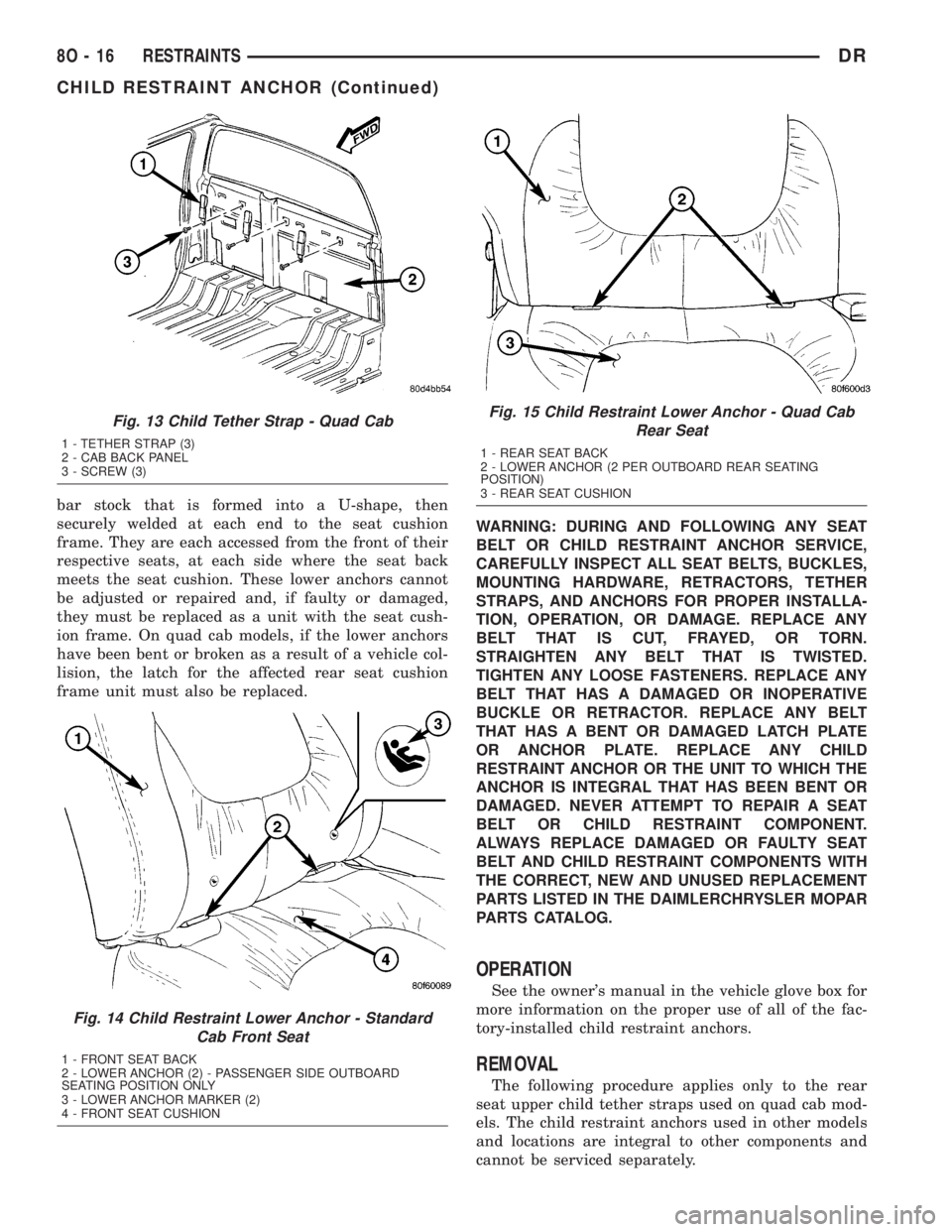
bar stock that is formed into a U-shape, then
securely welded at each end to the seat cushion
frame. They are each accessed from the front of their
respective seats, at each side where the seat back
meets the seat cushion. These lower anchors cannot
be adjusted or repaired and, if faulty or damaged,
they must be replaced as a unit with the seat cush-
ion frame. On quad cab models, if the lower anchors
have been bent or broken as a result of a vehicle col-
lision, the latch for the affected rear seat cushion
frame unit must also be replaced.WARNING: DURING AND FOLLOWING ANY SEAT
BELT OR CHILD RESTRAINT ANCHOR SERVICE,
CAREFULLY INSPECT ALL SEAT BELTS, BUCKLES,
MOUNTING HARDWARE, RETRACTORS, TETHER
STRAPS, AND ANCHORS FOR PROPER INSTALLA-
TION, OPERATION, OR DAMAGE. REPLACE ANY
BELT THAT IS CUT, FRAYED, OR TORN.
STRAIGHTEN ANY BELT THAT IS TWISTED.
TIGHTEN ANY LOOSE FASTENERS. REPLACE ANY
BELT THAT HAS A DAMAGED OR INOPERATIVE
BUCKLE OR RETRACTOR. REPLACE ANY BELT
THAT HAS A BENT OR DAMAGED LATCH PLATE
OR ANCHOR PLATE. REPLACE ANY CHILD
RESTRAINT ANCHOR OR THE UNIT TO WHICH THE
ANCHOR IS INTEGRAL THAT HAS BEEN BENT OR
DAMAGED. NEVER ATTEMPT TO REPAIR A SEAT
BELT OR CHILD RESTRAINT COMPONENT.
ALWAYS REPLACE DAMAGED OR FAULTY SEAT
BELT AND CHILD RESTRAINT COMPONENTS WITH
THE CORRECT, NEW AND UNUSED REPLACEMENT
PARTS LISTED IN THE DAIMLERCHRYSLER MOPAR
PARTS CATALOG.
OPERATION
See the owner's manual in the vehicle glove box for
more information on the proper use of all of the fac-
tory-installed child restraint anchors.
REMOVAL
The following procedure applies only to the rear
seat upper child tether straps used on quad cab mod-
els. The child restraint anchors used in other models
and locations are integral to other components and
cannot be serviced separately.
Fig. 13 Child Tether Strap - Quad Cab
1 - TETHER STRAP (3)
2 - CAB BACK PANEL
3 - SCREW (3)
Fig. 14 Child Restraint Lower Anchor - Standard
Cab Front Seat
1 - FRONT SEAT BACK
2 - LOWER ANCHOR (2) - PASSENGER SIDE OUTBOARD
SEATING POSITION ONLY
3 - LOWER ANCHOR MARKER (2)
4 - FRONT SEAT CUSHION
Fig. 15 Child Restraint Lower Anchor - Quad Cab
Rear Seat
1 - REAR SEAT BACK
2 - LOWER ANCHOR (2 PER OUTBOARD REAR SEATING
POSITION)
3 - REAR SEAT CUSHION
8O - 16 RESTRAINTSDR
CHILD RESTRAINT ANCHOR (Continued)
Page 635 of 2895
INSTALLATION
A traveling front outboard seat belt buckle is
located on the inboard side of each front outboard
seat section (40 percent) used on all models. The seat
belt buckle on the driver's side front seat for all mod-
els also includes a seat belt switch. (Refer to 8 -
ELECTRICAL/RESTRAINTS/SEAT BELT SWITCH -
DESCRIPTION).
WARNING: DURING AND FOLLOWING ANY SEAT
BELT OR CHILD RESTRAINT ANCHOR SERVICE,
CAREFULLY INSPECT ALL SEAT BELTS, BUCKLES,
MOUNTING HARDWARE, RETRACTORS, TETHER
STRAPS, AND ANCHORS FOR PROPER INSTALLA-
TION, OPERATION, OR DAMAGE. REPLACE ANY
BELT THAT IS CUT, FRAYED, OR TORN.
STRAIGHTEN ANY BELT THAT IS TWISTED.
TIGHTEN ANY LOOSE FASTENERS. REPLACE ANY
BELT THAT HAS A DAMAGED OR INOPERATIVE
BUCKLE OR RETRACTOR. REPLACE ANY BELT
THAT HAS A BENT OR DAMAGED LATCH PLATE
OR ANCHOR PLATE. REPLACE ANY CHILD
RESTRAINT ANCHOR OR THE UNIT TO WHICH THE
ANCHOR IS INTEGRAL THAT HAS BEEN BENT OR
DAMAGED. NEVER ATTEMPT TO REPAIR A SEAT
BELT OR CHILD RESTRAINT COMPONENT.
ALWAYS REPLACE DAMAGED OR FAULTY SEAT
BELT AND CHILD RESTRAINT COMPONENTS WITH
THE CORRECT, NEW AND UNUSED REPLACEMENTPARTS LISTED IN THE DAIMLERCHRYSLER MOPAR
PARTS CATALOG.
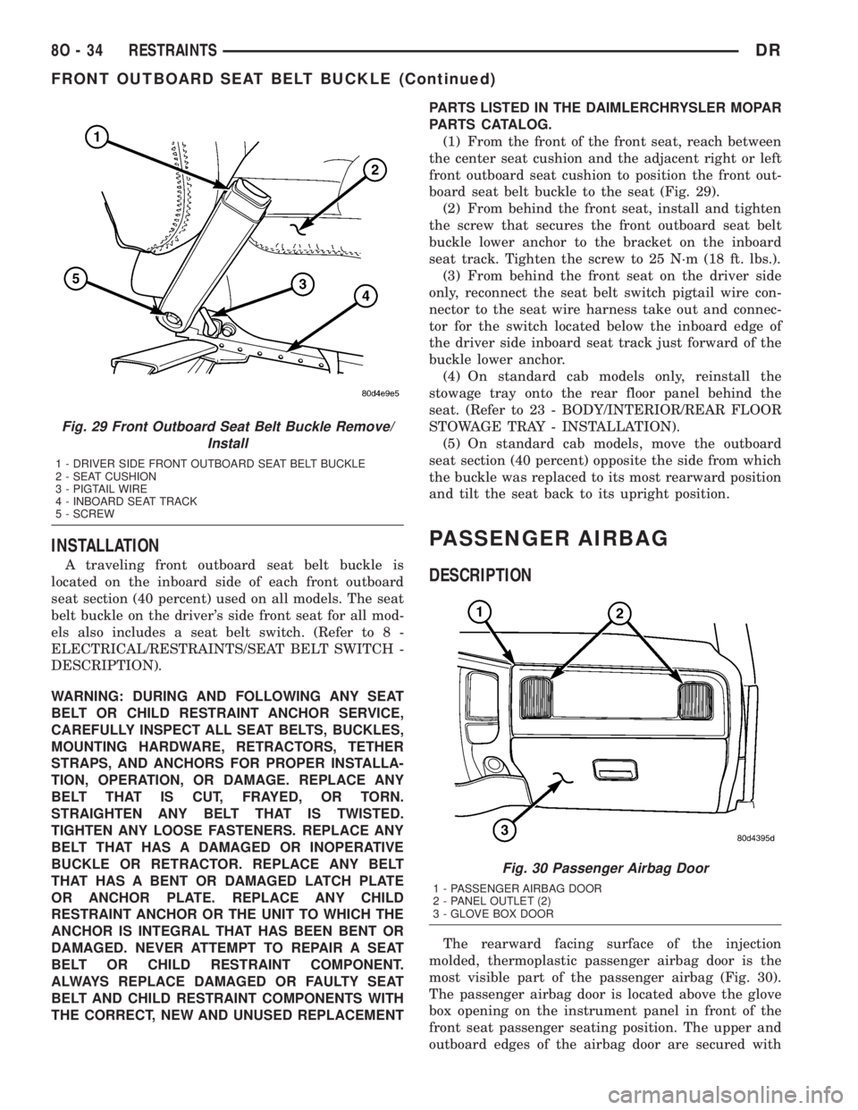
(1) From the front of the front seat, reach between
the center seat cushion and the adjacent right or left
front outboard seat cushion to position the front out-
board seat belt buckle to the seat (Fig. 29).
(2) From behind the front seat, install and tighten
the screw that secures the front outboard seat belt
buckle lower anchor to the bracket on the inboard
seat track. Tighten the screw to 25 N´m (18 ft. lbs.).
(3) From behind the front seat on the driver side
only, reconnect the seat belt switch pigtail wire con-
nector to the seat wire harness take out and connec-
tor for the switch located below the inboard edge of
the driver side inboard seat track just forward of the
buckle lower anchor.
(4) On standard cab models only, reinstall the
stowage tray onto the rear floor panel behind the
seat. (Refer to 23 - BODY/INTERIOR/REAR FLOOR
STOWAGE TRAY - INSTALLATION).
(5) On standard cab models, move the outboard
seat section (40 percent) opposite the side from which
the buckle was replaced to its most rearward position
and tilt the seat back to its upright position.
PASSENGER AIRBAG
DESCRIPTION
The rearward facing surface of the injection
molded, thermoplastic passenger airbag door is the
most visible part of the passenger airbag (Fig. 30).
The passenger airbag door is located above the glove
box opening on the instrument panel in front of the
front seat passenger seating position. The upper and
outboard edges of the airbag door are secured with
Fig. 29 Front Outboard Seat Belt Buckle Remove/
Install
1 - DRIVER SIDE FRONT OUTBOARD SEAT BELT BUCKLE
2 - SEAT CUSHION
3 - PIGTAIL WIRE
4 - INBOARD SEAT TRACK
5 - SCREW
Fig. 30 Passenger Airbag Door
1 - PASSENGER AIRBAG DOOR
2 - PANEL OUTLET (2)
3 - GLOVE BOX DOOR
8O - 34 RESTRAINTSDR
FRONT OUTBOARD SEAT BELT BUCKLE (Continued)
Page 636 of 2895
seven integral snap features to the instrument panel
base trim, while two screws secure the integral
inboard mounting flange to the base trim, and four
screws secure the lower mounting flange to the upper
glove box opening reinforcement integral to the
instrument panel structural support. The passenger
airbag door includes two air conditioning panel out-
lets and their housings. Each of the panel outlet
housings feature four snap features that secure them
to the back of the airbag door and two mounting tabs
that are also secured with one screw each to the
upper glove box opening reinforcement.
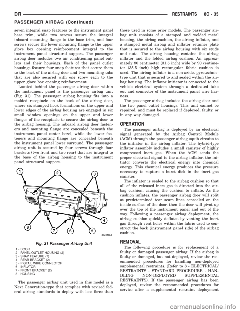
Located behind the passenger airbag door within
the instrument panel is the passenger airbag unit
(Fig. 31). The passenger airbag housing fits into a
molded receptacle on the back of the airbag door,
where six stamped hook formations on the upper and
lower edges of the airbag housing are engaged in six
small window openings on the upper and lower
flanges of the receptacle to secure the airbag door to
the airbag housing. The inboard airbag door fasten-
ers and mounting flange are concealed beneath the
instrument panel center bezel, while the lower fas-
teners and mounting flange are concealed beneath
the instrument panel lower surround. The passenger
airbag unit is secured by four screws through four
brackets (two front and two rear) that are integral to
the base of the airbag housing to the instrument
panel structural support.
The passenger airbag unit used in this model is a
Next Generation-type that complies with revised fed-
eral airbag standards to deploy with less force thanthose used in some prior models. The passenger air-
bag unit consists of a stamped and welded metal
housing, the airbag cushion, the airbag inflator, and
a stamped metal airbag and inflator retainer plate
that is secured to the airbag housing with six studs
and nuts. The airbag housing contains the airbag
inflator and the folded airbag cushion. An approxi-
mately 80 centimeter (31.5 inch) wide by 90 centime-
ter (35.5 inch) high rectangular fabric cushion is
used. The airbag inflator is a non-azide, pyrotechnic-
type unit that is secured to and sealed within the air-
bag housing. The inflator initiator is connected to the
vehicle electrical system through a dedicated take
out and connector of the instrument panel wire har-
ness.
The passenger airbag includes the airbag door and
the two panel outlet housings. This unit cannot be
repaired, and must be replaced if deployed, faulty, or
in any way damaged.
OPERATION
The passenger airbag is deployed by an electrical
signal generated by the Airbag Control Module
(ACM) through the passenger airbag squib circuits to
the initiator in the airbag inflator. The hybrid-type
inflator assembly includes a small canister of highly
compressed inert gas. When the ACM sends the
proper electrical signal to the airbag inflator, the ini-
tiator converts the electrical energy into chemical
energy. This chemical energy produces the pressure
necessary to rupture a burst disk in the inert gas
canister.
The inflator is sealed to the airbag cushion so that
all of the released inert gas is directed into the air-
bag cushion, causing the cushion to inflate. As the
cushion inflates, the passenger airbag door will split
at predetermined tear seam lines concealed on the
inside surface of the door, then the door will pivot up
over the top of the instrument panel and out of the
way. Following a passenger airbag deployment, the
airbag cushion quickly deflates by venting the inert
gas through vent holes within the fabric used to con-
struct the back (instrument panel side) of the airbag
cushion.
REMOVAL
The following procedure is for replacement of a
faulty or damaged passenger airbag. If the airbag is
faulty or damaged, but not deployed, review the rec-
ommended procedures for handling non-deployed
supplemental restraints. (Refer to 8 - ELECTRICAL/
RESTRAINTS - STANDARD PROCEDURE - HAN-
DLING NON-DEPLOYED SUPPLEMENTAL
RESTRAINTS). If the passenger airbag has been
deployed, review the recommended procedures for
service after a supplemental restraint deploymentFig. 31 Passenger Airbag Unit
1 - DOOR
2 - PANEL OUTLET HOUSING (2)
3 - SNAP FEATURE (7)
4 - REAR BRACKET (2)
5 - PIGTAIL WIRE CONNECTOR
6 - INFLATOR
7 - FRONT BRACKET (2)
8 - HOUSING
DRRESTRAINTS 8O - 35
PASSENGER AIRBAG (Continued)
Page 637 of 2895
before removing the airbag from the vehicle. (Refer to
8 - ELECTRICAL/RESTRAINTS - STANDARD PRO-
CEDURE - SERVICE AFTER A SUPPLEMENTAL
RESTRAINT DEPLOYMENT).
WARNING: ON VEHICLES EQUIPPED WITH AIR-
BAGS, DISABLE THE SUPPLEMENTAL RESTRAINT
SYSTEM BEFORE ATTEMPTING ANY STEERING
WHEEL, STEERING COLUMN, DRIVER AIRBAG,
PASSENGER AIRBAG, SEAT BELT TENSIONER,
SIDE CURTAIN AIRBAG, OR INSTRUMENT PANEL
COMPONENT DIAGNOSIS OR SERVICE. DISCON-
NECT AND ISOLATE THE BATTERY NEGATIVE
(GROUND) CABLE, THEN WAIT TWO MINUTES FOR
THE SYSTEM CAPACITOR TO DISCHARGE BEFORE
PERFORMING FURTHER DIAGNOSIS OR SERVICE.
THIS IS THE ONLY SURE WAY TO DISABLE THE
SUPPLEMENTAL RESTRAINT SYSTEM. FAILURE TO
TAKE THE PROPER PRECAUTIONS COULD
RESULT IN ACCIDENTAL AIRBAG DEPLOYMENT
AND POSSIBLE PERSONAL INJURY.
WARNING: WHEN REMOVING A DEPLOYED AIR-
BAG, RUBBER GLOVES, EYE PROTECTION, AND A
LONG-SLEEVED SHIRT SHOULD BE WORN. THERE
MAY BE DEPOSITS ON THE AIRBAG UNIT AND
OTHER INTERIOR SURFACES. IN LARGE DOSES,
THESE DEPOSITS MAY CAUSE IRRITATION TO THE
SKIN AND EYES.
(1) Disconnect and isolate the battery negative
cable. Wait two minutes for the system capacitor to
discharge before further service.
(2) Remove the lower surround from the instru-
ment panel. (Refer to 23 - BODY/INSTRUMENT
PANEL/LOWER SURROUND - REMOVAL).
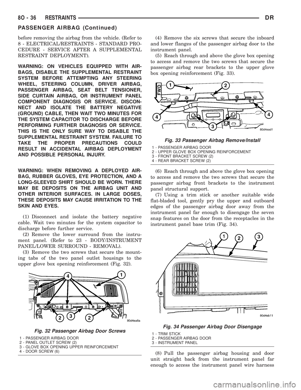
(3) Remove the two screws that secure the mount-
ing tabs of the two panel outlet housings to the
upper glove box opening reinforcement (Fig. 32).(4) Remove the six screws that secure the inboard
and lower flanges of the passenger airbag door to the
instrument panel.
(5) Reach through and above the glove box opening
to access and remove the two screws that secure the
passenger airbag rear brackets to the upper glove
box opening reinforcement (Fig. 33).
(6) Reach through and above the glove box opening
to access and remove the two screws that secure the
passenger airbag front brackets to the instrument
panel structural support.
(7) Using a trim stick or another suitable wide
flat-bladed tool, gently pry the upper and outboard
edges of the passenger airbag door away from the
instrument panel far enough to disengage the seven
snap features on the door from the receptacles in the
instrument panel base trim (Fig. 34).
(8) Pull the passenger airbag housing and door
unit straight back from the instrument panel far
enough to access the instrument panel wire harness
Fig. 32 Passenger Airbag Door Screws
1 - PASSENGER AIRBAG DOOR
2 - PANEL OUTLET SCREW (2)
3 - GLOVE BOX OPENING UPPER REINFORCEMENT
4 - DOOR SCREW (6)
Fig. 33 Passenger Airbag Remove/Install
1 - PASSENGER AIRBAG DOOR
2 - UPPER GLOVE BOX OPENING REINFORCEMENT
3 - FRONT BRACKET SCREW (2)
4 - REAR BRACKET SCREW (2)
Fig. 34 Passenger Airbag Door Disengage
1 - TRIM STICK
2 - PASSENGER AIRBAG DOOR
3 - INSTRUMENT PANEL
8O - 36 RESTRAINTSDR
PASSENGER AIRBAG (Continued)
Page 638 of 2895
take out and connector for the airbag inflator located
on the inboard side of the housing.
(9) Disconnect the instrument panel wire harness
connector for the passenger airbag from the connec-
tor receptacle on the airbag inflator.
(10) Remove the passenger airbag and airbag door
from the instrument panel as a unit.
INSTALLATION
The following procedure is for replacement of a
faulty or damaged passenger airbag. If the airbag is
faulty or damaged, but not deployed, review the rec-
ommended procedures for handling non-deployed
supplemental restraints. (Refer to 8 - ELECTRICAL/
RESTRAINTS - STANDARD PROCEDURE - HAN-
DLING NON-DEPLOYED SUPPLEMENTAL
RESTRAINTS). If the passenger airbag has been
deployed, review the recommended procedures for
service after a supplemental restraint deployment
before removing the airbag from the vehicle. (Refer to
8 - ELECTRICAL/RESTRAINTS - STANDARD PRO-
CEDURE - SERVICE AFTER A SUPPLEMENTAL
RESTRAINT DEPLOYMENT).
WARNING: ON VEHICLES EQUIPPED WITH AIR-
BAGS, DISABLE THE SUPPLEMENTAL RESTRAINT
SYSTEM BEFORE ATTEMPTING ANY STEERING
WHEEL, STEERING COLUMN, DRIVER AIRBAG,
PASSENGER AIRBAG, SEAT BELT TENSIONER,
SIDE CURTAIN AIRBAG, OR INSTRUMENT PANEL
COMPONENT DIAGNOSIS OR SERVICE. DISCON-
NECT AND ISOLATE THE BATTERY NEGATIVE
(GROUND) CABLE, THEN WAIT TWO MINUTES FOR
THE SYSTEM CAPACITOR TO DISCHARGE BEFORE
PERFORMING FURTHER DIAGNOSIS OR SERVICE.
THIS IS THE ONLY SURE WAY TO DISABLE THE
SUPPLEMENTAL RESTRAINT SYSTEM. FAILURE TO
TAKE THE PROPER PRECAUTIONS COULD
RESULT IN ACCIDENTAL AIRBAG DEPLOYMENT
AND POSSIBLE PERSONAL INJURY.
WARNING: WHEN REMOVING A DEPLOYED AIR-
BAG, RUBBER GLOVES, EYE PROTECTION, AND A
LONG-SLEEVED SHIRT SHOULD BE WORN. THERE
MAY BE DEPOSITS ON THE AIRBAG UNIT AND
OTHER INTERIOR SURFACES. IN LARGE DOSES,
THESE DEPOSITS MAY CAUSE IRRITATION TO THE
SKIN AND EYES.
WARNING: USE EXTREME CARE TO PREVENT ANY
FOREIGN MATERIAL FROM ENTERING THE PAS-
SENGER AIRBAG, OR BECOMING ENTRAPPED
BETWEEN THE PASSENGER AIRBAG CUSHION
AND THE PASSENGER AIRBAG DOOR. FAILURE TOOBSERVE THIS WARNING COULD RESULT IN
OCCUPANT INJURIES UPON AIRBAG DEPLOY-
MENT.
WARNING: THE PASSENGER AIRBAG DOOR MUST
NEVER BE PAINTED. REPLACEMENT PASSENGER
AIRBAG UNITS ARE SERVICED WITH DOORS IN
THE ORIGINAL COLORS. PAINT MAY CHANGE THE
WAY IN WHICH THE MATERIAL OF THE AIRBAG
DOOR RESPONDS TO AN AIRBAG DEPLOYMENT.
FAILURE TO OBSERVE THIS WARNING COULD
RESULT IN OCCUPANT INJURIES UPON AIRBAG
DEPLOYMENT.
(1) Carefully position the passenger airbag and
airbag door to the instrument panel as a unit.
(2) Reconnect the instrument panel wire harness
connector for the passenger airbag to the connector
receptacle on the airbag inflator. Be certain that the
connector latches are fully engaged.
(3) Position the passenger airbag housing and door
unit into the instrument panel.
(4) Using hand pressure, press firmly and evenly
over each of the seven snap features on the upper
and outboard edges of the passenger airbag door
until they snap into their receptacles in the instru-
ment panel base trim.
(5) Reach through and above the glove box opening
to install and tighten the two screws that secure the
passenger airbag front brackets to the instrument
panel structural support (Fig. 33). Tighten the screws
to 6 N´m (55 in. lbs.).
(6) Reach through and above the glove box opening
to install and tighten the two screws that secure the
passenger airbag rear brackets to the upper glove
box opening reinforcement. Tighten the screws to 6
N´m (55 in. lbs.).
(7) Install and tighten the six screws that secure
the inboard and lower flanges of the passenger air-
bag door to the instrument panel (Fig. 32). Tighten
the screws to 2 N´m (20 in. lbs.).
(8) Install and tighten the two screws that secure
the mounting tabs of the two panel outlet housings to
the upper glove box opening reinforcement. Tighten
the screws to 2 N´m (20 in. lbs.).
(9) Reinstall the lower surround onto the instru-
ment panel. (Refer to 23 - BODY/INSTRUMENT
PANEL/LOWER SURROUND - INSTALLATION).
(10) Do not reconnect the battery negative cable at
this time. The supplemental restraint system verifi-
cation test procedure should be performed following
service of any supplemental restraint system compo-
nent. (Refer to 8 - ELECTRICAL/RESTRAINTS -
STANDARD PROCEDURE - VERIFICATION TEST).
DRRESTRAINTS 8O - 37
PASSENGER AIRBAG (Continued)
Page 639 of 2895
PASSENGER AIRBAG ON/OFF
SWITCH
DESCRIPTION
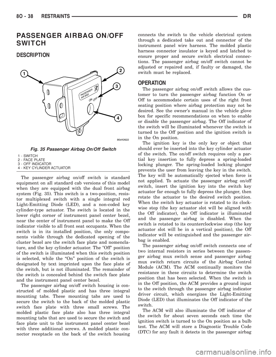
The passenger airbag on/off switch is standard
equipment on all standard cab versions of this model
when they are equipped with the dual front airbag
system (Fig. 35). This switch is a two-position, resis-
tor multiplexed switch with a single integral red
Light-Emitting Diode (LED), and a non-coded key
cylinder-type actuator. The switch is located in the
lower right corner of instrument panel center bezel,
near the center of instrument panel to make the Off
indicator visible to all front seat occupants. When the
switch is in its installed position, the only compo-
nents visible through the dedicated opening of the
cluster bezel are the switch face plate and nomencla-
ture, and the key cylinder actuator. The9Off9position
of the switch is illuminated when this switch position
is selected, while the ªOnº position of the switch is
designated by text imprinted upon the face plate of
the switch, but is not illuminated. The remainder of
the switch is concealed behind the switch face plate
and the instrument panel center bezel.
The passenger airbag on/off switch housing is con-
structed of molded plastic and has three integral
mounting tabs. These mounting tabs are used to
secure the switch to the back of the molded plastic
switch face plate with three small screws. The
molded plastic face plate also has three integral
mounting tabs that are used to secure the switch and
face plate unit to the instrument panel center bezel
with three additional screws. A molded plastic con-
nector receptacle on the back of the switch housingconnects the switch to the vehicle electrical system
through a dedicated take out and connector of the
instrument panel wire harness. The molded plastic
harness connector insulator is keyed and latched to
ensure proper and secure switch electrical connec-
tions. The passenger airbag on/off switch cannot be
adjusted or repaired and, if faulty or damaged, the
switch must be replaced.
OPERATION
The passenger airbag on/off switch allows the cus-
tomer to turn the passenger airbag function On or
Off to accommodate certain uses of the right front
seating position where airbag protection may not be
desired. See the owner's manual in the vehicle glove
box for specific recommendations on when to enable
or disable the passenger airbag. The Off indicator of
the switch will be illuminated whenever the switch is
turned to the Off position and the ignition switch is
in the On position.
The ignition key is the only key or object that
should ever be inserted into the key cylinder actuator
of the switch. The on/off switch requires only a par-
tial key insertion to fully depress a spring-loaded
locking plunger. The spring-loaded locking plunger
prevents the user from leaving the key in the switch.
The key will be automatically ejected when force is
not applied. To actuate the passenger airbag on/off
switch, insert the ignition key into the switch key
actuator far enough to fully depress the plunger, then
rotate the actuator to the desired switch position.
When the switch key actuator is rotated to its clock-
wise stop (the key actuator slot will be aligned with
the Off indicator), the Off indicator is illuminated
and the passenger airbag is disabled. When the
switch is rotated to its counterclockwise stop (the key
actuator slot will be in a vertical position), the Off
indicator will be extinguished and the passenger air-
bag is enabled.
The passenger airbag on/off switch connects one of
two internal resistors in series between the passen-
ger airbag mux switch sense and passenger airbag
mux switch return circuits of the Airbag Control
Module (ACM). The ACM continually monitors the
resistance in these circuits to determine the switch
position that has been selected. When the switch is
in the Off position, the ACM provides a ground input
to the switch through the passenger airbag indicator
driver circuit, which energizes the Light-Emitting
Diode (LED) that illuminates the Off indicator of the
switch.
The ACM will also illuminate the Off indicator of
the switch for about seven seconds each time the
ignition switch is turned to the On position as a bulb
test. The ACM will store a Diagnostic Trouble Code
(DTC) for any fault it detects in the passenger airbag
Fig. 35 Passenger Airbag On/Off Switch
1 - SWITCH
2 - FACE PLATE
3 - OFF INDICATOR
4 - KEY CYLINDER ACTUATOR
8O - 38 RESTRAINTSDR
Page 720 of 2895
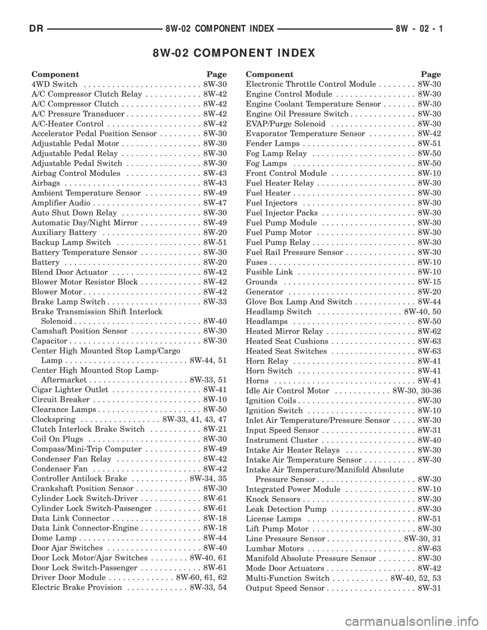
8W-02 COMPONENT INDEX
Component Page
4WD Switch......................... 8W-30
A/C Compressor Clutch Relay............ 8W-42
A/C Compressor Clutch................. 8W-42
A/C Pressure Transducer................ 8W-42
A/C-Heater Control.................... 8W-42
Accelerator Pedal Position Sensor......... 8W-30
Adjustable Pedal Motor................. 8W-30
Adjustable Pedal Relay................. 8W-30
Adjustable Pedal Switch................ 8W-30
Airbag Control Modules................ 8W-43
Airbags............................. 8W-43
Ambient Temperature Sensor............ 8W-49
Amplifier Audio....................... 8W-47
Auto Shut Down Relay................. 8W-30
Automatic Day/Night Mirror............. 8W-49
Auxiliary Battery..................... 8W-20
Backup Lamp Switch.................. 8W-51
Battery Temperature Sensor............. 8W-30
Battery............................. 8W-20
Blend Door Actuator................... 8W-42
Blower Motor Resistor Block............. 8W-42
Blower Motor......................... 8W-42
Brake Lamp Switch.................... 8W-33
Brake Transmission Shift Interlock
Solenoid........................... 8W-40
Camshaft Position Sensor............... 8W-30
Capacitor............................ 8W-30
Center High Mounted Stop Lamp/Cargo
Lamp.......................... 8W-44, 51
Center High Mounted Stop Lamp-
Aftermarket..................... 8W-33, 51
Cigar Lighter Outlet................... 8W-41
Circuit Breaker....................... 8W-10
Clearance Lamps...................... 8W-50
Clockspring................. 8W-33, 41, 43, 47
Clutch Interlock Brake Switch........... 8W-21
Coil On Plugs........................ 8W-30
Compass/Mini-Trip Computer............ 8W-49
Condenser Fan Relay.................. 8W-42
Condenser Fan....................... 8W-42
Controller Antilock Brake............ 8W-34, 35
Crankshaft Position Sensor.............. 8W-30
Cylinder Lock Switch-Driver............. 8W-61
Cylinder Lock Switch-Passenger.......... 8W-61
Data Link Connector................... 8W-18
Data Link Connector-Engine............. 8W-18
Dome Lamp.......................... 8W-44
Door Ajar Switches.................... 8W-40
Door Lock Motor/Ajar Switches........ 8W-40, 61
Door Lock Switch-Passenger............. 8W-61
Driver Door Module.............. 8W-60, 61, 62
Electric Brake Provision............. 8W-33, 54Component Page
Electronic Throttle Control Module........ 8W-30
Engine Control Module................. 8W-30
Engine Coolant Temperature Sensor....... 8W-30
Engine Oil Pressure Switch.............. 8W-30
EVAP/Purge Solenoid.................. 8W-30
Evaporator Temperature Sensor.......... 8W-42
Fender Lamps........................ 8W-51
Fog Lamp Relay...................... 8W-50
Fog Lamps.......................... 8W-50
Front Control Module.................. 8W-10
Fuel Heater Relay..................... 8W-30
Fuel Heater.......................... 8W-30
Fuel Injectors........................ 8W-30
Fuel Injector Packs.................... 8W-30
Fuel Pump Module.................... 8W-30
Fuel Pump Motor..................... 8W-30
Fuel Pump Relay...................... 8W-30
Fuel Rail Pressure Sensor............... 8W-30
Fuses............................... 8W-10
Fusible Link......................... 8W-10
Grounds............................ 8W-15
Generator........................... 8W-20
Glove Box Lamp And Switch............. 8W-44
Headlamp Switch.................. 8W-40, 50
Headlamps.......................... 8W-50
Heated Mirror Relay................... 8W-62
Heated Seat Cushions.................. 8W-63
Heated Seat Switches.................. 8W-63
Horn Relay.......................... 8W-41
Horn Switch......................... 8W-41
Horns.............................. 8W-41
Idle Air Control Motor............ 8W-30, 30-36
Ignition Coils......................... 8W-30
Ignition Switch....................... 8W-10
Inlet Air Temperature/Pressure Sensor..... 8W-30
Input Speed Sensor.................... 8W-31
Instrument Cluster.................... 8W-40
Intake Air Heater Relays............... 8W-30
Intake Air Temperature Sensor........... 8W-30
Intake Air Temperature/Manifold Absolute
Pressure Sensor..................... 8W-30
Integrated Power Module............... 8W-10
Knock Sensors........................ 8W-30
Leak Detection Pump.................. 8W-30
License Lamps....................... 8W-51
Lift Pump Motor...................... 8W-30
Line Pressure Sensor................ 8W-30, 31
Lumbar Motors....................... 8W-63
Manifold Absolute Pressure Sensor........ 8W-30
Mode Door Actuators................... 8W-42
Multi-Function Switch............ 8W-40, 52, 53
Output Speed Sensor................... 8W-31
DR8W-02 COMPONENT INDEX 8W - 02 - 1
Page 722 of 2895
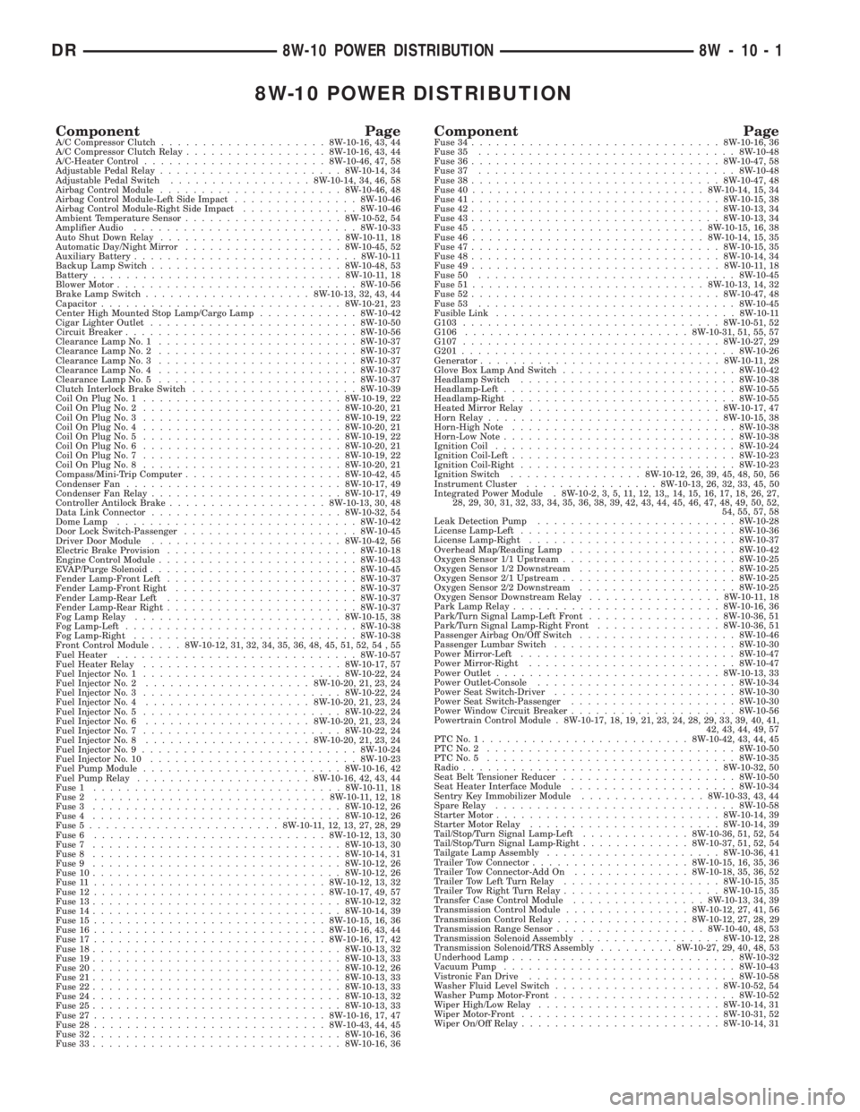
8W-10 POWER DISTRIBUTION
Component PageA/C Compressor Clutch....................8W-10-16, 43, 44
A/C Compressor Clutch Relay.................8W-10-16, 43, 44
A/C-Heater Control......................8W-10-46, 47, 58
Adjustable Pedal Relay......................8W-10-14, 34
Adjustable Pedal Switch.................8W-10-14, 34, 46, 58
Airbag Control Module......................8W-10-46, 48
Airbag Control Module-Left Side Impact...............8W-10-46
Airbag Control Module-Right Side Impact..............8W-10-46
Ambient Temperature Sensor...................8W-10-52, 54
Amplifier Audio...........................8W-10-33
Auto Shut Down Relay......................8W-10-11, 18
Automatic Day/Night Mirror...................8W-10-45, 52
Auxiliary Battery...........................8W-10-11
Backup Lamp Switch.......................8W-10-48, 53
Battery..............................8W-10-11, 18
Blower Motor.............................8W-10-56
Brake Lamp Switch....................8W-10-13, 32, 43, 44
Capacitor.............................8W-10-21, 23
Center High Mounted Stop Lamp/Cargo Lamp............8W-10-42
Cigar Lighter Outlet.........................8W-10-50
Circuit Breaker............................8W-10-56
Clearance Lamp No. 1........................8W-10-37
Clearance Lamp No. 2........................8W-10-37
Clearance Lamp No. 3........................8W-10-37
Clearance Lamp No. 4........................8W-10-37
Clearance Lamp No. 5........................8W-10-37
Clutch Interlock Brake Switch....................8W-10-39
Coil On Plug No. 1........................8W-10-19, 22
Coil On Plug No. 2........................8W-10-20, 21
Coil On Plug No. 3........................8W-10-19, 22
Coil On Plug No. 4........................8W-10-20, 21
Coil On Plug No. 5........................8W-10-19, 22
Coil On Plug No. 6........................8W-10-20, 21
Coil On Plug No. 7........................8W-10-19, 22
Coil On Plug No. 8........................8W-10-20, 21
Compass/Mini-Trip Computer...................8W-10-42, 45
Condenser Fan..........................8W-10-17, 49
Condenser Fan Relay.......................8W-10-17, 49
Controller Antilock Brake...................8W-10-13, 30, 48
Data Link Connector.......................8W-10-32, 54
Dome Lamp.............................8W-10-42
Door Lock Switch-Passenger.....................8W-10-45
Driver Door Module.......................8W-10-42, 56
Electric Brake Provision.......................8W-10-18
Engine Control Module........................8W-10-43
EVAP/Purge Solenoid.........................8W-10-45
Fender Lamp-Front Left.......................8W-10-37
Fender Lamp-Front Right......................8W-10-37
Fender Lamp-Rear Left.......................8W-10-37
Fender Lamp-Rear Right.......................8W-10-37
Fog Lamp Relay.........................8W-10-15, 38
Fog Lamp-Left............................8W-10-38
Fog Lamp-Right...........................8W-10-38
Front Control Module....8W-10-12, 31, 32, 34, 35, 36, 48, 45, 51, 52, 54 , 55
Fuel Heater.............................8W-10-57
Fuel Heater Relay........................8W-10-17, 57
Fuel Injector No. 1........................8W-10-22, 24
Fuel Injector No. 2....................8W-10-20, 21, 23, 24
Fuel Injector No. 3........................8W-10-22, 24
Fuel Injector No. 4....................8W-10-20, 21, 23, 24
Fuel Injector No. 5........................8W-10-22, 24
Fuel Injector No. 6....................8W-10-20, 21, 23, 24
Fuel Injector No. 7........................8W-10-22, 24
Fuel Injector No. 8....................8W-10-20, 21, 23, 24
Fuel Injector No. 9..........................8W-10-24
Fuel Injector No. 10.........................8W-10-23
Fuel Pump Module........................8W-10-16, 42
Fuel Pump Relay.....................8W-10-16, 42, 43, 44
Fuse 1..............................8W-10-11, 18
Fuse 2............................8W-10-11, 12, 18
Fuse 3..............................8W-10-12, 26
Fuse 4..............................8W-10-12, 26
Fuse 5.......................8W-10-11, 12, 13, 27, 28, 29
Fuse 6............................8W-10-12, 13, 30
Fuse 7..............................8W-10-13, 30
Fuse 8..............................8W-10-14, 31
Fuse 9..............................8W-10-12, 26
Fuse 10..............................8W-10-12, 26
Fuse 11............................8W-10-12, 13, 32
Fuse 12............................8W-10-17, 49, 57
Fuse 13..............................8W-10-12, 32
Fuse 14..............................8W-10-14, 39
Fuse 15............................8W-10-15, 16, 36
Fuse 16............................8W-10-16, 43, 44
Fuse 17............................8W-10-16, 17, 42
Fuse 18..............................8W-10-13, 32
Fuse 19..............................8W-10-13, 33
Fuse 20..............................8W-10-12, 26
Fuse 21..............................8W-10-13, 33
Fuse 22..............................8W-10-13, 33
Fuse 24..............................8W-10-13, 32
Fuse 25..............................8W-10-13, 33
Fuse 27............................8W-10-16, 17, 47
Fuse 28............................8W-10-43, 44, 45
Fuse 32..............................8W-10-16, 36
Fuse 33..............................8W-10-16, 36Component PageFuse 34..............................8W-10-16, 36
Fuse 35...............................8W-10-48
Fuse 36..............................8W-10-47, 58
Fuse 37...............................8W-10-48
Fuse 38..............................8W-10-47, 48
Fuse 40............................8W-10-14, 15, 34
Fuse 41..............................8W-10-15, 38
Fuse 42..............................8W-10-13, 34
Fuse 43..............................8W-10-13, 34
Fuse 45............................8W-10-15, 16, 38
Fuse 46............................8W-10-14, 15, 35
Fuse 47..............................8W-10-15, 35
Fuse 48..............................8W-10-14, 34
Fuse 49..............................8W-10-11, 18
Fuse 50...............................8W-10-45
Fuse 51............................8W-10-13, 14, 32
Fuse 52..............................8W-10-47, 48
Fuse 53...............................8W-10-45
Fusible Link.............................8W-10-11
G103...............................8W-10-51, 52
G106...........................8W-10-31, 51, 55, 57
G107...............................8W-10-27, 29
G201.................................8W-10-26
Generator.............................8W-10-11, 28
Glove Box Lamp And Switch.....................8W-10-42
Headlamp Switch..........................8W-10-38
Headlamp-Left............................8W-10-55
Headlamp-Right...........................8W-10-55
Heated Mirror Relay.......................8W-10-17, 47
Horn Relay............................8W-10-15, 38
Horn-High Note...........................8W-10-38
Horn-Low Note............................8W-10-38
Ignition Coil.............................8W-10-24
Ignition Coil-Left...........................8W-10-23
Ignition Coil-Right..........................8W-10-23
Ignition Switch................8W-10-12, 26, 39, 45, 48, 50, 56
Instrument Cluster................8W-10-13, 26, 32, 33, 45, 50
Integrated Power Module . 8W-10-2, 3, 5, 11, 12, 13,, 14, 15, 16, 17, 18, 26, 27,
28, 29, 30, 31, 32, 33, 34, 35, 36, 38, 39, 42, 43, 44, 45, 46, 47, 48, 49, 50, 52,
54, 55, 57, 58
Leak Detection Pump........................8W-10-28
License Lamp-Left..........................8W-10-36
License Lamp-Right.........................8W-10-37
Overhead Map/Reading Lamp....................8W-10-42
Oxygen Sensor 1/1 Upstream.....................8W-10-25
Oxygen Sensor 1/2 Downstream...................8W-10-25
Oxygen Sensor 2/1 Upstream.....................8W-10-25
Oxygen Sensor 2/2 Downstream...................8W-10-25
Oxygen Sensor Downstream Relay................8W-10-11, 18
Park Lamp Relay.........................8W-10-16, 36
Park/Turn Signal Lamp-Left Front................8W-10-36, 51
Park/Turn Signal Lamp-Right Front...............8W-10-36, 51
Passenger Airbag On/Off Switch...................8W-10-46
Passenger Lumbar Switch......................8W-10-30
Power Mirror-Left..........................8W-10-47
Power Mirror-Right.........................8W-10-47
Power Outlet...........................8W-10-13, 33
Power Outlet-Console........................8W-10-34
Power Seat Switch-Driver......................8W-10-30
Power Seat Switch-Passenger....................8W-10-30
Power Window Circuit Breaker....................8W-10-56
Powertrain Control Module . 8W-10-17, 18, 19, 21, 23, 24, 28, 29, 33, 39, 40, 41,
42, 43, 44, 49, 57
PTCNo.1.........................8W-10-42, 43, 44, 45
PTCNo.2 ..............................8W-10-50
PTCNo.5 ..............................8W-10-35
Radio...............................8W-10-32, 50
Seat Belt Tensioner Reducer.....................8W-10-50
Seat Heater Interface Module....................8W-10-34
Sentry Key Immobilizer Module...............8W-10-33, 43, 44
Spare Relay.............................8W-10-58
Starter Motor...........................8W-10-14, 39
Starter Motor Relay.......................8W-10-14, 39
Tail/Stop/Turn Signal Lamp-Left.............8W-10-36, 51, 52, 54
Tail/Stop/Turn Signal Lamp-Right.............8W-10-37, 51, 52, 54
Tailgate Lamp Assembly.....................8W-10-36, 41
Trailer Tow Connector...................8W-10-15, 16, 35, 36
Trailer Tow Connector-Add On..............8W-10-18, 35, 36, 52
Trailer Tow Left Turn Relay...................8W-10-15, 35
Trailer Tow Right Turn Relay...................8W-10-15, 35
Transfer Case Control Module................8W-10-13, 34, 39
Transmission Control Module...............8W-10-12, 27, 41, 56
Transmission Control Relay................8W-10-12, 27, 28, 29
Transmission Range Sensor..................8W-10-40, 48, 53
Transmission Solenoid Assembly.................8W-10-12, 28
Transmission Solenoid/TRS Assembly.........8W-10-27, 29, 40, 48, 53
Underhood Lamp...........................8W-10-32
Vacuum Pump............................8W-10-43
Vistronic Fan Drive.........................8W-10-58
Washer Fluid Level Switch....................8W-10-52, 54
Washer Pump Motor-Front......................8W-10-52
Wiper High/Low Relay......................8W-10-14, 31
Wiper Motor-Front........................8W-10-31, 52
Wiper On/Off Relay........................8W-10-14, 31
DR8W-10 POWER DISTRIBUTION 8W - 10 - 1