ignition coil DODGE RAM 2003 Service Owner's Manual
[x] Cancel search | Manufacturer: DODGE, Model Year: 2003, Model line: RAM, Model: DODGE RAM 2003Pages: 2895, PDF Size: 83.15 MB
Page 487 of 2895
REMOVAL
3.7L V-6
Each individual spark plug is located under each
ignition coil. Each individual ignition coil must be
removed to gain access to each spark plug. Refer to
Ignition Coil Removal/Installation.
(1) Remove necessary air filter tubing at throttle
body.
(2) Prior to removing ignition coil, spray com-
pressed air around coil base at cylinder head.
(3) Prior to removing spark plug, spray com-
pressed air into cylinder head opening. This will help
prevent foreign material from entering combustion
chamber.
(4) Remove spark plug from cylinder head using a
quality socket with a rubber or foam insert. Also
check condition of ignition coil o-ring and replace as
necessary.
(5) Inspect spark plug condition. Refer to Diagnos-
tics and Testing - Spark Plug Conditions.
4.7L V-8
Each individual spark plug is located under each
ignition coil. Each individual ignition coil must be
removed to gain access to each spark plug. Refer to
Ignition Coil Removal/Installation.
(1) Remove necessary air filter tubing at throttle
body.
(2) Prior to removing ignition coil, spray com-
pressed air around coil base at cylinder head.
(3) Prior to removing spark plug, spray com-
pressed air into cylinder head opening. This will help
prevent foreign material from entering combustion
chamber.
(4) Remove spark plug from cylinder head using a
quality socket with a rubber or foam insert. Also
check condition of ignition coil o-ring and replace as
necessary.
(5) Inspect spark plug condition. Refer to Diagnos-
tics and Testing - Spark Plug Conditions.
5.7L V-8
Eight of the 16 spark plugs are located under an
ignition coil; the other 8 are not. If spark plug being
removed is under coil, coil must be removed to gain
access to spark plug. Refer to Ignition Coil Removal/
Installation and observe all CAUTIONS and WARN-
INGS.
Before removing or disconnecting any spark plug
cables, note their original position. Remove cables
one-at-a-time. To prevent ignition crossfire, spark
plug cablesMUSTbe placed in cable tray (routing
loom) into their original position. Refer to Spark Plug
Cable Removal for a graphic.Before installing spark plug cables to either the
spark plugs or coils, apply dielectric grease to inside
of boots.
(1) Remove necessary air filter tubing at throttle
body.
(2) Prior to removing ignition coil (if coil removal
is necessary), spray compressed air around coil base
at cylinder head cover.
(3) Prior to removing spark plug, spray com-
pressed air into cylinder head opening. This will help
prevent foreign material from entering combustion
chamber.
(4) Remove spark plug from cylinder head using a
quality socket with a rubber or foam insert.
(5) Inspect spark plug condition. Refer to Diagnos-
tics and Testing - Spark Plug Conditions.
5.9L V-8
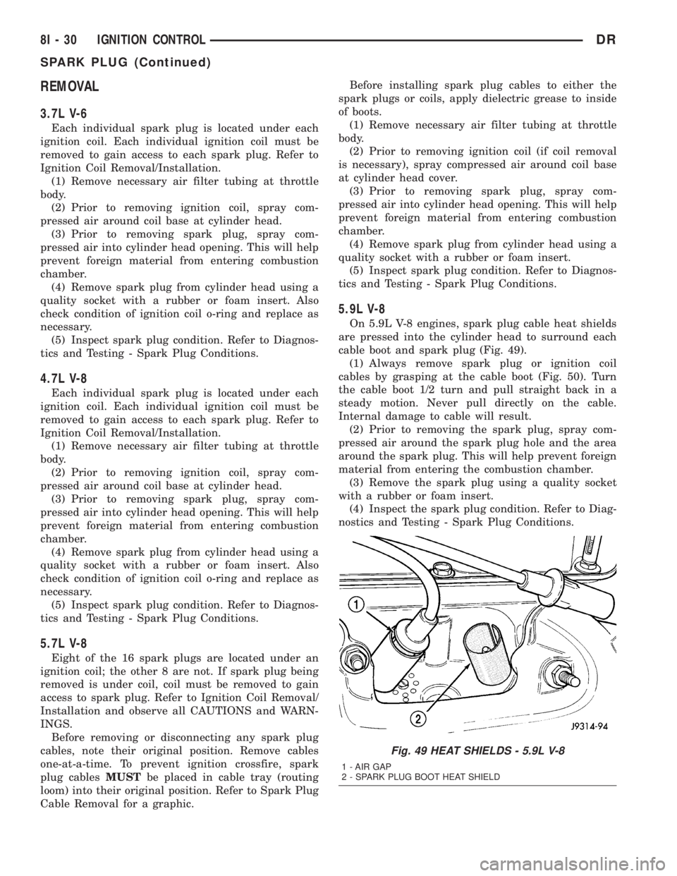
On 5.9L V-8 engines, spark plug cable heat shields
are pressed into the cylinder head to surround each
cable boot and spark plug (Fig. 49).
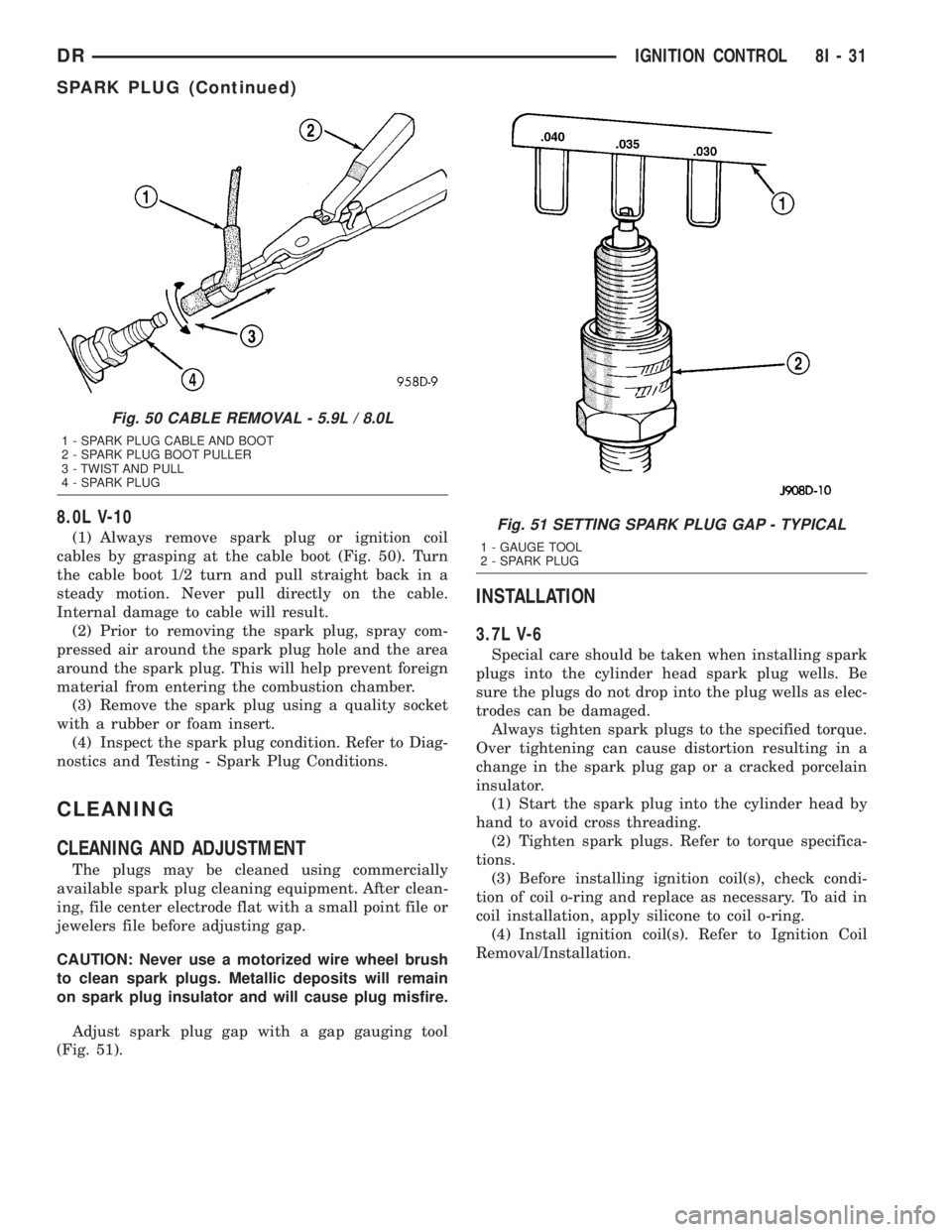
(1) Always remove spark plug or ignition coil
cables by grasping at the cable boot (Fig. 50). Turn
the cable boot 1/2 turn and pull straight back in a
steady motion. Never pull directly on the cable.
Internal damage to cable will result.
(2) Prior to removing the spark plug, spray com-
pressed air around the spark plug hole and the area
around the spark plug. This will help prevent foreign
material from entering the combustion chamber.
(3) Remove the spark plug using a quality socket
with a rubber or foam insert.
(4) Inspect the spark plug condition. Refer to Diag-
nostics and Testing - Spark Plug Conditions.
Fig. 49 HEAT SHIELDS - 5.9L V-8
1 - AIR GAP
2 - SPARK PLUG BOOT HEAT SHIELD
8I - 30 IGNITION CONTROLDR
SPARK PLUG (Continued)
Page 488 of 2895
8.0L V-10
(1) Always remove spark plug or ignition coil
cables by grasping at the cable boot (Fig. 50). Turn
the cable boot 1/2 turn and pull straight back in a
steady motion. Never pull directly on the cable.
Internal damage to cable will result.
(2) Prior to removing the spark plug, spray com-
pressed air around the spark plug hole and the area
around the spark plug. This will help prevent foreign
material from entering the combustion chamber.
(3) Remove the spark plug using a quality socket
with a rubber or foam insert.
(4) Inspect the spark plug condition. Refer to Diag-
nostics and Testing - Spark Plug Conditions.
CLEANING
CLEANING AND ADJUSTMENT
The plugs may be cleaned using commercially
available spark plug cleaning equipment. After clean-
ing, file center electrode flat with a small point file or
jewelers file before adjusting gap.
CAUTION: Never use a motorized wire wheel brush
to clean spark plugs. Metallic deposits will remain
on spark plug insulator and will cause plug misfire.
Adjust spark plug gap with a gap gauging tool
(Fig. 51).
INSTALLATION
3.7L V-6
Special care should be taken when installing spark
plugs into the cylinder head spark plug wells. Be
sure the plugs do not drop into the plug wells as elec-
trodes can be damaged.
Always tighten spark plugs to the specified torque.
Over tightening can cause distortion resulting in a
change in the spark plug gap or a cracked porcelain
insulator.
(1) Start the spark plug into the cylinder head by
hand to avoid cross threading.
(2) Tighten spark plugs. Refer to torque specifica-
tions.
(3) Before installing ignition coil(s), check condi-
tion of coil o-ring and replace as necessary. To aid in
coil installation, apply silicone to coil o-ring.
(4) Install ignition coil(s). Refer to Ignition Coil
Removal/Installation.
Fig. 50 CABLE REMOVAL - 5.9L / 8.0L
1 - SPARK PLUG CABLE AND BOOT
2 - SPARK PLUG BOOT PULLER
3 - TWIST AND PULL
4 - SPARK PLUG
Fig. 51 SETTING SPARK PLUG GAP - TYPICAL
1 - GAUGE TOOL
2 - SPARK PLUG
DRIGNITION CONTROL 8I - 31
SPARK PLUG (Continued)
Page 489 of 2895
4.7L V-8
CAUTION: The 4.7L V±8 engine is equipped with
copper core ground electrode spark plugs. They
must be replaced with the same type/number spark
plug as the original. If another spark plug is substi-
tuted, pre-ignition will result.
Special care should be taken when installing spark
plugs into the cylinder head spark plug wells. Be
sure the plugs do not drop into the plug wells as elec-
trodes can be damaged.
Always tighten spark plugs to the specified torque.
Over tightening can cause distortion resulting in a
change in the spark plug gap or a cracked porcelain
insulator.
(1) Start the spark plug into the cylinder head by
hand to avoid cross threading.
(2) Tighten spark plugs. Refer to torque specifica-
tions.
(3) Before installing ignition coil(s), check condi-
tion of coil o-ring and replace as necessary. To aid in
coil installation, apply silicone to coil o-ring.
(4) Install ignition coil(s). Refer to Ignition Coil
Removal/Installation.
5.7L V-8
(1) Special care should be taken when installing
spark plugs into the cylinder head spark plug wells.
Be sure the plugs do not drop into the plug wells as
electrodes can be damaged.
(2) Start the spark plug into cylinder head by
hand to avoid cross threading aluminum threads. To
aid in installation, attach a piece of rubber hose, or
an old spark plug boot to spark plug.
(3) The 5.7L V-8 is equipped with torque critical
design spark plugs. Do not exceed 15 ft. lbs. torque.
Tighten spark plugs. Refer to torque specifications.
(4) Before installing spark plug cables to either the
spark plugs or coils, apply dielectric grease to inside
of boots.
(5) To prevent ignition crossfire, spark plug cables
MUSTbe placed in cable tray (routing loom) into
their original position. Refer to Spark Plug Cable
Removal for a graphic.
(6) Install ignition coil(s) to necessary spark plugs.
Refer to Ignition Coil Installation.
(7) Install spark plug cables to remaining spark
plugs. Remember to apply dielectric grease to inside
of boots.
5.9L V-8
Special care should be taken when installing spark
plugs into the cylinder head spark plug wells. Be
sure the plugs do not drop into the plug wells as elec-
trodes can be damaged.
Always tighten spark plugs to the specified torque.
Over tightening can cause distortion resulting in a
change in the spark plug gap or a cracked porcelain
insulator.
When replacing the spark plug and ignition coil
cables, route the cables correctly and secure them in
the appropriate retainers. Failure to route the cables
properly can cause the radio to reproduce ignition
noise. It could cause cross ignition of the spark plugs
or short circuit the cables to ground.
(1) Start the spark plug into the cylinder head by
hand to avoid cross threading.
(2) Tighten spark plugs. Refer to torque specifica-
tions.
(3) Install spark plug cables to spark plugs. On
5.9L V-8 engines, spark plug cable heat shields are
pressed into the cylinder head to surround each
spark plug cable boot and spark plug (Fig. 53). These
shields protect the spark plug boots from damage
(due to intense engine heat generated by the exhaust
manifolds) and should not be removed. After the
spark plug cable has been installed, the lip of the
cable boot should have a small air gap to the top of
the heat shield (Fig. 53).
8.0L V-10
Special care should be taken when installing spark
plugs into the cylinder head spark plug wells. Be
sure the plugs do not drop into the plug wells as elec-
trodes can be damaged.
Always tighten spark plugs to the specified torque.
Over tightening can cause distortion resulting in a
change in the spark plug gap or a cracked porcelain
insulator.
When replacing the spark plug and ignition coil
cables, route the cables correctly and secure them in
the appropriate retainers. Failure to route the cables
properly can cause the radio to reproduce ignition
noise. It could cause cross ignition of the spark plugs
or short circuit the cables to ground.
(1) Start the spark plug into the cylinder head by
hand to avoid cross threading.
(2) Tighten spark plugs. Refer to torque specifica-
tions.
(3) Install spark plug cables to spark plugs.
8I - 32 IGNITION CONTROLDR
SPARK PLUG (Continued)
Page 490 of 2895
IGNITION COIL CAPACITOR
DESCRIPTION
One coil capacitor is used. It is located in the right-
rear section of the engine compartment.
OPERATION
The coil capacitor(s) help dampen the amount of
conducted electrical noise to the camshaft position
sensor, crankshaft position sensor, and throttle posi-
tion sensor. This noise is generated on the 12V sup-
ply wire to the ignition coils and fuel injectors.
REMOVAL
The coil capacitor is located in the right-rear sec-
tion of the engine compartment. It is attached with a
mounting stud and nut.
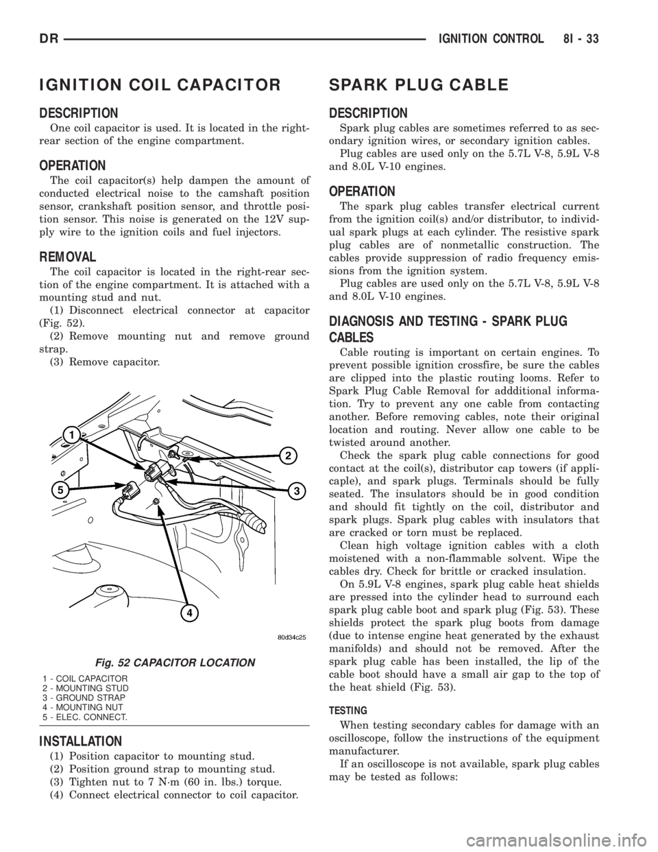
(1) Disconnect electrical connector at capacitor
(Fig. 52).
(2) Remove mounting nut and remove ground
strap.
(3) Remove capacitor.
INSTALLATION
(1) Position capacitor to mounting stud.
(2) Position ground strap to mounting stud.
(3) Tighten nut to 7 N´m (60 in. lbs.) torque.
(4) Connect electrical connector to coil capacitor.
SPARK PLUG CABLE
DESCRIPTION
Spark plug cables are sometimes referred to as sec-
ondary ignition wires, or secondary ignition cables.
Plug cables are used only on the 5.7L V-8, 5.9L V-8
and 8.0L V-10 engines.
OPERATION
The spark plug cables transfer electrical current
from the ignition coil(s) and/or distributor, to individ-
ual spark plugs at each cylinder. The resistive spark
plug cables are of nonmetallic construction. The
cables provide suppression of radio frequency emis-
sions from the ignition system.
Plug cables are used only on the 5.7L V-8, 5.9L V-8
and 8.0L V-10 engines.
DIAGNOSIS AND TESTING - SPARK PLUG
CABLES
Cable routing is important on certain engines. To
prevent possible ignition crossfire, be sure the cables
are clipped into the plastic routing looms. Refer to
Spark Plug Cable Removal for addditional informa-
tion. Try to prevent any one cable from contacting
another. Before removing cables, note their original
location and routing. Never allow one cable to be
twisted around another.
Check the spark plug cable connections for good
contact at the coil(s), distributor cap towers (if appli-
caple), and spark plugs. Terminals should be fully
seated. The insulators should be in good condition
and should fit tightly on the coil, distributor and
spark plugs. Spark plug cables with insulators that
are cracked or torn must be replaced.
Clean high voltage ignition cables with a cloth
moistened with a non-flammable solvent. Wipe the
cables dry. Check for brittle or cracked insulation.
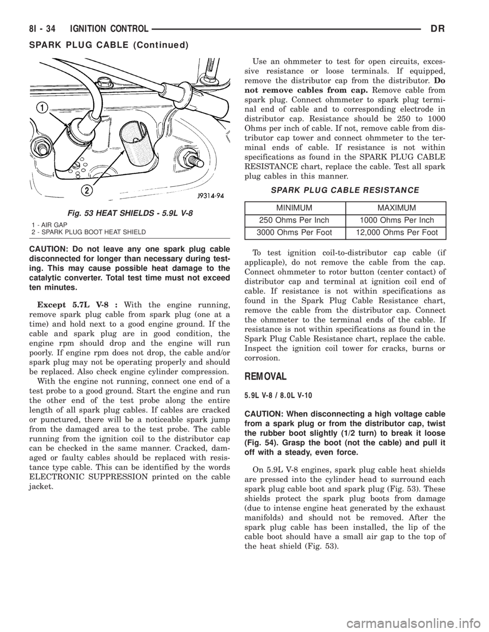
On 5.9L V-8 engines, spark plug cable heat shields
are pressed into the cylinder head to surround each
spark plug cable boot and spark plug (Fig. 53). These
shields protect the spark plug boots from damage
(due to intense engine heat generated by the exhaust
manifolds) and should not be removed. After the
spark plug cable has been installed, the lip of the
cable boot should have a small air gap to the top of
the heat shield (Fig. 53).
TESTING
When testing secondary cables for damage with an
oscilloscope, follow the instructions of the equipment
manufacturer.
If an oscilloscope is not available, spark plug cables
may be tested as follows:
Fig. 52 CAPACITOR LOCATION
1 - COIL CAPACITOR
2 - MOUNTING STUD
3 - GROUND STRAP
4 - MOUNTING NUT
5 - ELEC. CONNECT.
DRIGNITION CONTROL 8I - 33
Page 491 of 2895
CAUTION: Do not leave any one spark plug cable
disconnected for longer than necessary during test-
ing. This may cause possible heat damage to the
catalytic converter. Total test time must not exceed
ten minutes.
Except 5.7L V-8 :With the engine running,
remove spark plug cable from spark plug (one at a
time) and hold next to a good engine ground. If the
cable and spark plug are in good condition, the
engine rpm should drop and the engine will run
poorly. If engine rpm does not drop, the cable and/or
spark plug may not be operating properly and should
be replaced. Also check engine cylinder compression.
With the engine not running, connect one end of a
test probe to a good ground. Start the engine and run
the other end of the test probe along the entire
length of all spark plug cables. If cables are cracked
or punctured, there will be a noticeable spark jump
from the damaged area to the test probe. The cable
running from the ignition coil to the distributor cap
can be checked in the same manner. Cracked, dam-
aged or faulty cables should be replaced with resis-
tance type cable. This can be identified by the words
ELECTRONIC SUPPRESSION printed on the cable
jacket.Use an ohmmeter to test for open circuits, exces-
sive resistance or loose terminals. If equipped,
remove the distributor cap from the distributor.Do
not remove cables from cap.Remove cable from
spark plug. Connect ohmmeter to spark plug termi-
nal end of cable and to corresponding electrode in
distributor cap. Resistance should be 250 to 1000
Ohms per inch of cable. If not, remove cable from dis-
tributor cap tower and connect ohmmeter to the ter-
minal ends of cable. If resistance is not within
specifications as found in the SPARK PLUG CABLE
RESISTANCE chart, replace the cable. Test all spark
plug cables in this manner.
SPARK PLUG CABLE RESISTANCE
MINIMUM MAXIMUM
250 Ohms Per Inch 1000 Ohms Per Inch
3000 Ohms Per Foot 12,000 Ohms Per Foot
To test ignition coil-to-distributor cap cable (if
applicaple), do not remove the cable from the cap.
Connect ohmmeter to rotor button (center contact) of
distributor cap and terminal at ignition coil end of
cable. If resistance is not within specifications as
found in the Spark Plug Cable Resistance chart,
remove the cable from the distributor cap. Connect
the ohmmeter to the terminal ends of the cable. If
resistance is not within specifications as found in the
Spark Plug Cable Resistance chart, replace the cable.
Inspect the ignition coil tower for cracks, burns or
corrosion.
REMOVAL
5.9L V-8 / 8.0L V-10
CAUTION: When disconnecting a high voltage cable
from a spark plug or from the distributor cap, twist
the rubber boot slightly (1/2 turn) to break it loose
(Fig. 54). Grasp the boot (not the cable) and pull it
off with a steady, even force.
On 5.9L V-8 engines, spark plug cable heat shields
are pressed into the cylinder head to surround each
spark plug cable boot and spark plug (Fig. 53). These
shields protect the spark plug boots from damage
(due to intense engine heat generated by the exhaust
manifolds) and should not be removed. After the
spark plug cable has been installed, the lip of the
cable boot should have a small air gap to the top of
the heat shield (Fig. 53).
Fig. 53 HEAT SHIELDS - 5.9L V-8
1 - AIR GAP
2 - SPARK PLUG BOOT HEAT SHIELD
8I - 34 IGNITION CONTROLDR
SPARK PLUG CABLE (Continued)
Page 492 of 2895
5.7L V-8
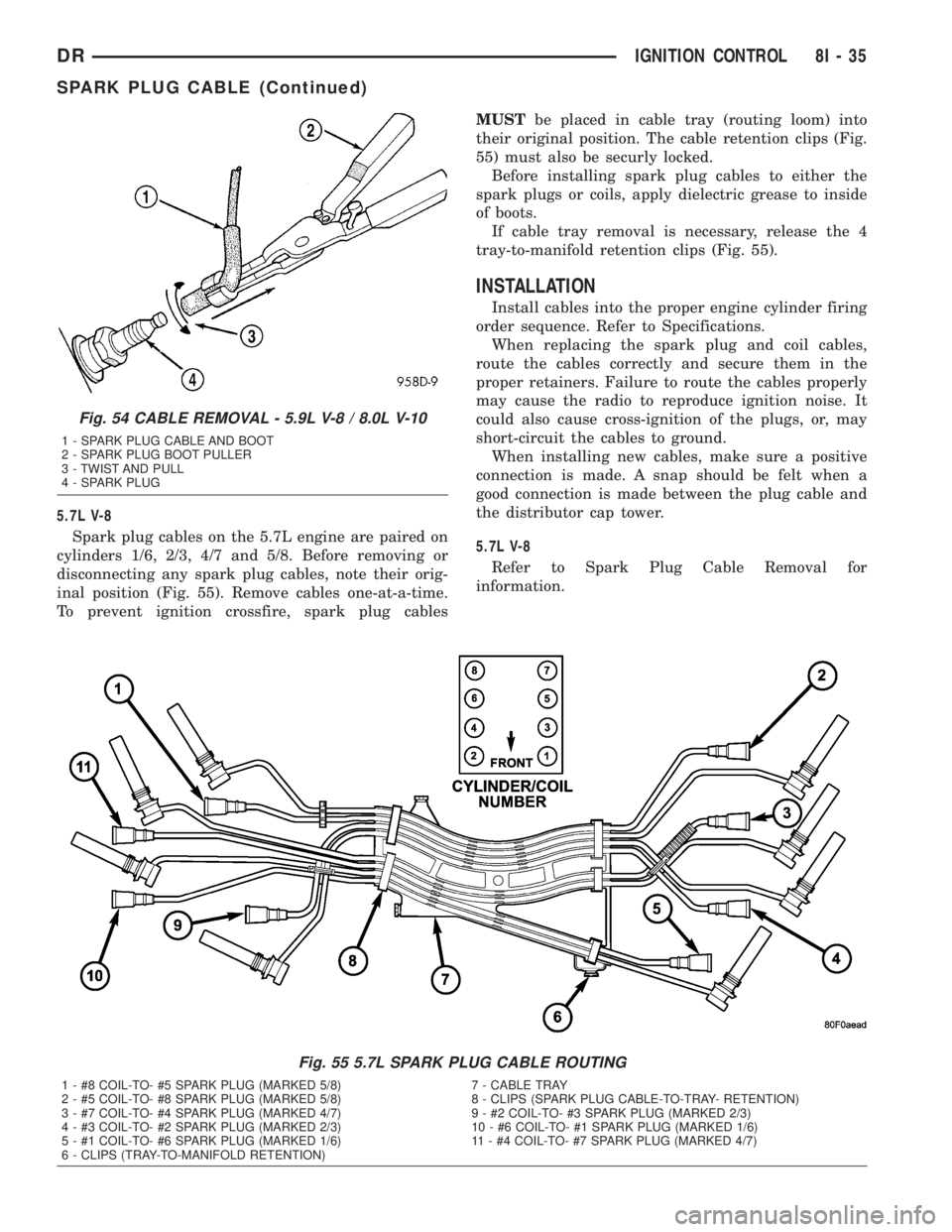
Spark plug cables on the 5.7L engine are paired on
cylinders 1/6, 2/3, 4/7 and 5/8. Before removing or
disconnecting any spark plug cables, note their orig-
inal position (Fig. 55). Remove cables one-at-a-time.
To prevent ignition crossfire, spark plug cablesMUSTbe placed in cable tray (routing loom) into
their original position. The cable retention clips (Fig.
55) must also be securly locked.
Before installing spark plug cables to either the
spark plugs or coils, apply dielectric grease to inside
of boots.
If cable tray removal is necessary, release the 4
tray-to-manifold retention clips (Fig. 55).
INSTALLATION
Install cables into the proper engine cylinder firing
order sequence. Refer to Specifications.
When replacing the spark plug and coil cables,
route the cables correctly and secure them in the
proper retainers. Failure to route the cables properly
may cause the radio to reproduce ignition noise. It
could also cause cross-ignition of the plugs, or, may
short-circuit the cables to ground.
When installing new cables, make sure a positive
connection is made. A snap should be felt when a
good connection is made between the plug cable and
the distributor cap tower.
5.7L V-8
Refer to Spark Plug Cable Removal for
information.
Fig. 55 5.7L SPARK PLUG CABLE ROUTING
1 - #8 COIL-TO- #5 SPARK PLUG (MARKED 5/8) 7 - CABLE TRAY
2 - #5 COIL-TO- #8 SPARK PLUG (MARKED 5/8) 8 - CLIPS (SPARK PLUG CABLE-TO-TRAY- RETENTION)
3 - #7 COIL-TO- #4 SPARK PLUG (MARKED 4/7) 9 - #2 COIL-TO- #3 SPARK PLUG (MARKED 2/3)
4 - #3 COIL-TO- #2 SPARK PLUG (MARKED 2/3) 10 - #6 COIL-TO- #1 SPARK PLUG (MARKED 1/6)
5 - #1 COIL-TO- #6 SPARK PLUG (MARKED 1/6) 11 - #4 COIL-TO- #7 SPARK PLUG (MARKED 4/7)
6 - CLIPS (TRAY-TO-MANIFOLD RETENTION)
Fig. 54 CABLE REMOVAL - 5.9L V-8 / 8.0L V-10
1 - SPARK PLUG CABLE AND BOOT
2 - SPARK PLUG BOOT PULLER
3 - TWIST AND PULL
4 - SPARK PLUG
DRIGNITION CONTROL 8I - 35
SPARK PLUG CABLE (Continued)
Page 501 of 2895
dles at several predetermined calibration points
across the gauge faces, and illuminating all segments
of the odometer/trip odometer and gear selector indi-
cator Vacuum-Fluorescent Display (VFD) units.
(Refer to 8 - ELECTRICAL/INSTRUMENT CLUS-
TER - DIAGNOSIS AND TESTING). See the owner's
manual in the vehicle glove box for more information
on the features, use and operation of the EMIC.
GAUGES
All gauges receive battery current through the
EMIC circuitry only when the ignition switch is in
the On or Start positions. With the ignition switch in
the Off position battery current is not supplied to
any gauges, and the EMIC circuitry is programmed
to move all of the gauge needles back to the low end
of their respective scales. Therefore, the gauges do
not accurately indicate any vehicle condition unless
the ignition switch is in the On or Start positions.
All of the EMIC gauges are air core magnetic
units. Two fixed electromagnetic coils are located
within each gauge. These coils are wrapped at right
angles to each other around a movable permanent
magnet. The movable magnet is suspended within
the coils on one end of a pivot shaft, while the gauge
needle is attached to the other end of the shaft. One
of the coils has a fixed current flowing through it to
maintain a constant magnetic field strength. Current
flow through the second coil changes, which causes
changes in its magnetic field strength. The current
flowing through the second coil is changed by the
EMIC circuitry in response to messages received over
the PCI data bus. The gauge needle moves as the
movable permanent magnet aligns itself to the
changing magnetic fields created around it by the
electromagnets.
The gauges are diagnosed using the EMIC self-di-
agnostic actuator test. (Refer to 8 - ELECTRICAL/
INSTRUMENT CLUSTER - DIAGNOSIS AND
TESTING). Proper testing of the PCI data bus and
the electronic data bus message inputs to the EMIC
that control each gauge require the use of a DRBIIIt
scan tool. Refer to the appropriate diagnostic infor-
mation. Specific operation details for each gauge may
be found elsewhere in this service information.
VACUUM-FLUORESCENT DISPLAYS
The Vacuum-Fluorescent Display (VFD) units are
soldered to the EMIC electronic circuit board. With
the ignition switch in the Off or Accessory positions,
the odometer display is activated when the driver
door is opened (Rental Car mode) and is deactivated
when the driver door is closed. Otherwise, both dis-
play units are active when the ignition switch is in
the On or Start positions, and inactive when the igni-
tion switch is in the Off or Accessory positions.The illumination intensity of the VFD units is con-
trolled by the EMIC circuitry based upon an input
from the headlamp switch and a dimming level input
received from the headlamp dimmer switch. The
EMIC synchronizes the illumination intensity of
other VFD units with that of the units in the EMIC
by sending electronic dimming level messages to
other electronic modules in the vehicle over the PCI
data bus.
The EMIC VFD units have several display capabil-
ities including odometer, trip odometer, engine hours,
gear selector indication (PRNDL) for models with an
automatic transmission, several warning or reminder
indications, and various diagnostic information when
certain fault conditions exist. An odometer/trip odom-
eter switch on the EMIC circuit board is used to con-
trol some of the display modes. This switch is
actuated manually by depressing the odometer/trip
odometer switch button that extends through the
lower edge of the cluster lens, just left of the tachom-
eter. Actuating this switch momentarily with the
ignition switch in the On position will toggle the
VFD between the odometer and trip odometer modes.
Depressing the switch button for about two seconds
while the VFD is in the trip odometer mode will
reset the trip odometer value to zero. While in the
odometer mode with the ignition switch in the On
position and the engine not running, depressing this
switch for about six seconds will display the engine
hours information. Holding this switch depressed
while turning the ignition switch from the Off posi-
tion to the On position will initiate the EMIC self-di-
agnostic actuator test. Refer to the appropriate
diagnostic information for additional details on this
VFD function. The EMIC microprocessor remembers
which display mode is active when the ignition
switch is turned to the Off position, and returns the
VFD display to that mode when the ignition switch is
turned On again.
The VFD units are diagnosed using the EMIC self-
diagnostic actuator test. (Refer to 8 - ELECTRICAL/
INSTRUMENT CLUSTER - DIAGNOSIS AND
TESTING). Proper testing of the PCI data bus and
the electronic data bus message inputs to the EMIC
that control some of the VFD functions requires the
use of a DRBIIItscan tool. Refer to the appropriate
diagnostic information. Specific operation details for
the odometer, the trip odometer, the gear selector
indicator and the various warning and reminder indi-
cator functions of the VFD may be found elsewhere
in this service information.
INDICATORS
Indicators are located in various positions within
the EMIC and are all connected to the EMIC elec-
tronic circuit board. The cargo lamp indicator, door
8J - 8 INSTRUMENT CLUSTERDR
INSTRUMENT CLUSTER (Continued)
Page 650 of 2895
outboard seat belt and retractor unit must be
replaced. (Refer to 8 - ELECTRICAL/RESTRAINTS/
FRONT OUTBOARD SEAT BELT & RETRACTOR -
REMOVAL).
OPERATION
The seat belt tension reducer is controlled by a
ground signal received from the seat belt switch on
the seat belt switch sense circuit and a battery cur-
rent signal received from the ignition switch on the
fused ignition switch output (run-accessory) circuit.
When the seat belt switch is closed (the driver side
front seat belt is fastened) and the ignition switch is
in the On or Accessory positions, the seat belt tension
reducer solenoid is energized. When the solenoid is
energized, it actuates a mechanism within the driver
side front outboard seat belt retractor to reduce the
normal recoil spring tension exerted by the retractor
spool, which is designed to reel in the seat belt web-
bing onto the spool. When the driver side seat belt is
unbuckled or if the ignition switch is turned to any
position except On or Accessory, the tension reducer
solenoid is de-energized and the normal recoil spring
tension of the retractor is restored.
The action of the seat belt tension reducer results
in improved seat belt comfort for the driver. Reducing
the seat belt retractor recoil spring tension is desir-
able on standard cab models of this vehicle and not
on the quad cab model due to the different mounting
position required for the seat belt turning loop on the
B-pillar relative to the driver's seat position on the
standard cab model. The seat belt tension reducer
may be diagnosed using conventional diagnostic tools
and methods.
DIAGNOSIS AND TESTING - SEAT BELT
TENSION REDUCER
Refer to the appropriate wiring information. The
wiring information includes wiring diagrams, proper
wire and connector repair procedures, details of wire
harness routing and retention, connector pin-out
information and location views for the various wire
harness connectors, splices and grounds.
WARNING: ON VEHICLES EQUIPPED WITH AIR-
BAGS, DISABLE THE SUPPLEMENTAL RESTRAINTSYSTEM BEFORE ATTEMPTING ANY STEERING
WHEEL, STEERING COLUMN, DRIVER AIRBAG,
PASSENGER AIRBAG, SEAT BELT TENSIONER,
SIDE CURTAIN AIRBAG, OR INSTRUMENT PANEL
COMPONENT DIAGNOSIS OR SERVICE. DISCON-
NECT AND ISOLATE THE BATTERY NEGATIVE
(GROUND) CABLE, THEN WAIT TWO MINUTES FOR
THE SYSTEM CAPACITOR TO DISCHARGE BEFORE
PERFORMING FURTHER DIAGNOSIS OR SERVICE.
THIS IS THE ONLY SURE WAY TO DISABLE THE
SUPPLEMENTAL RESTRAINT SYSTEM. FAILURE TO
TAKE THE PROPER PRECAUTIONS COULD
RESULT IN ACCIDENTAL AIRBAG DEPLOYMENT
AND POSSIBLE PERSONAL INJURY.
(1) Disconnect and isolate the battery negative
cable. Disconnect the body wire harness connector for
the seat belt tension reducer from the tension
reducer connector receptacle on the driver side front
outboard seat belt and retractor unit. Using an ohm-
meter, measure the resistance between the seat belt
switch sense circuit terminal pin and the fused igni-
tion switch output (run-accessory) circuit terminal
pin in the tension reducer connector receptacle on
the retractor. Resistance through the tension reducer
solenoid coil should be 53 ohms at 20É C (68É F). If
OK, go to Step 2. If not OK, replace the faulty driver
side front outboard seat belt and retractor unit.
(2) Check for continuity between the seat belt
switch sense circuit cavity of the body wire harness
connector for the seat belt tension reducer and a good
ground. There should be continuity with the driver
side front seat belt buckled, and no continuity with
the driver side front seat belt unbuckled. If OK, go to
Step 3. If not OK, repair the shorted or open seat
belt switch sense circuit between the tension reducer
and the seat belt switch as required.
(3) Reconnect the battery negative cable. Check for
battery current at the fused ignition switch output
(run-accessory) circuit of the body wire harness con-
nector for the seat belt tension reducer. There should
be battery current with the ignition switch in the On
or Accessory positions, and no battery current with
the ignition switch in any other position. If not OK,
repair the shorted or open fused ignition switch out-
put (run-accessory) circuit between the tension
reducer and the ignition switch as required.
DRRESTRAINTS 8O - 49
SEAT BELT TENSION REDUCER (Continued)
Page 696 of 2895
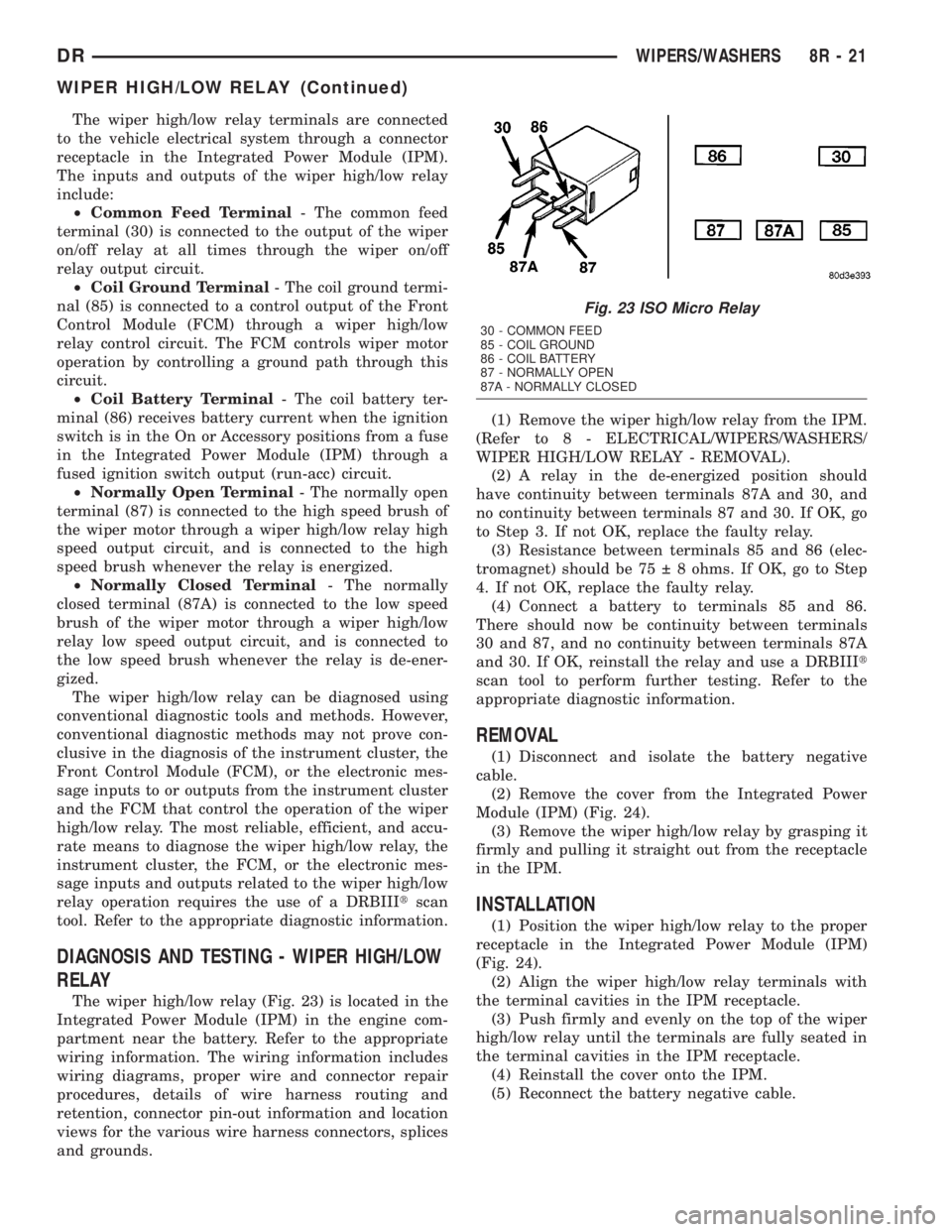
The wiper high/low relay terminals are connected
to the vehicle electrical system through a connector
receptacle in the Integrated Power Module (IPM).
The inputs and outputs of the wiper high/low relay
include:
²Common Feed Terminal- The common feed
terminal (30) is connected to the output of the wiper
on/off relay at all times through the wiper on/off
relay output circuit.
²Coil Ground Terminal- The coil ground termi-
nal (85) is connected to a control output of the Front
Control Module (FCM) through a wiper high/low
relay control circuit. The FCM controls wiper motor
operation by controlling a ground path through this
circuit.
²Coil Battery Terminal- The coil battery ter-
minal (86) receives battery current when the ignition
switch is in the On or Accessory positions from a fuse
in the Integrated Power Module (IPM) through a
fused ignition switch output (run-acc) circuit.
²Normally Open Terminal- The normally open
terminal (87) is connected to the high speed brush of
the wiper motor through a wiper high/low relay high
speed output circuit, and is connected to the high
speed brush whenever the relay is energized.
²Normally Closed Terminal- The normally
closed terminal (87A) is connected to the low speed
brush of the wiper motor through a wiper high/low
relay low speed output circuit, and is connected to
the low speed brush whenever the relay is de-ener-
gized.
The wiper high/low relay can be diagnosed using
conventional diagnostic tools and methods. However,
conventional diagnostic methods may not prove con-
clusive in the diagnosis of the instrument cluster, the
Front Control Module (FCM), or the electronic mes-
sage inputs to or outputs from the instrument cluster
and the FCM that control the operation of the wiper
high/low relay. The most reliable, efficient, and accu-
rate means to diagnose the wiper high/low relay, the
instrument cluster, the FCM, or the electronic mes-
sage inputs and outputs related to the wiper high/low
relay operation requires the use of a DRBIIItscan
tool. Refer to the appropriate diagnostic information.
DIAGNOSIS AND TESTING - WIPER HIGH/LOW
RELAY
The wiper high/low relay (Fig. 23) is located in the
Integrated Power Module (IPM) in the engine com-
partment near the battery. Refer to the appropriate
wiring information. The wiring information includes
wiring diagrams, proper wire and connector repair
procedures, details of wire harness routing and
retention, connector pin-out information and location
views for the various wire harness connectors, splices
and grounds.(1) Remove the wiper high/low relay from the IPM.
(Refer to 8 - ELECTRICAL/WIPERS/WASHERS/
WIPER HIGH/LOW RELAY - REMOVAL).
(2) A relay in the de-energized position should
have continuity between terminals 87A and 30, and
no continuity between terminals 87 and 30. If OK, go
to Step 3. If not OK, replace the faulty relay.
(3) Resistance between terminals 85 and 86 (elec-
tromagnet) should be 75 8 ohms. If OK, go to Step
4. If not OK, replace the faulty relay.
(4) Connect a battery to terminals 85 and 86.
There should now be continuity between terminals
30 and 87, and no continuity between terminals 87A
and 30. If OK, reinstall the relay and use a DRBIIIt
scan tool to perform further testing. Refer to the
appropriate diagnostic information.
REMOVAL
(1) Disconnect and isolate the battery negative
cable.
(2) Remove the cover from the Integrated Power
Module (IPM) (Fig. 24).
(3) Remove the wiper high/low relay by grasping it
firmly and pulling it straight out from the receptacle
in the IPM.
INSTALLATION
(1) Position the wiper high/low relay to the proper
receptacle in the Integrated Power Module (IPM)
(Fig. 24).
(2) Align the wiper high/low relay terminals with
the terminal cavities in the IPM receptacle.
(3) Push firmly and evenly on the top of the wiper
high/low relay until the terminals are fully seated in
the terminal cavities in the IPM receptacle.
(4) Reinstall the cover onto the IPM.
(5) Reconnect the battery negative cable.
Fig. 23 ISO Micro Relay
30 - COMMON FEED
85 - COIL GROUND
86 - COIL BATTERY
87 - NORMALLY OPEN
87A - NORMALLY CLOSED
DRWIPERS/WASHERS 8R - 21
WIPER HIGH/LOW RELAY (Continued)
Page 700 of 2895
WIPER ON/OFF RELAY
DESCRIPTION
The wiper on/off relay is located in the Integrated
Power Module (IPM) in the engine compartment near
the battery. The wiper on/off relay is a conventional
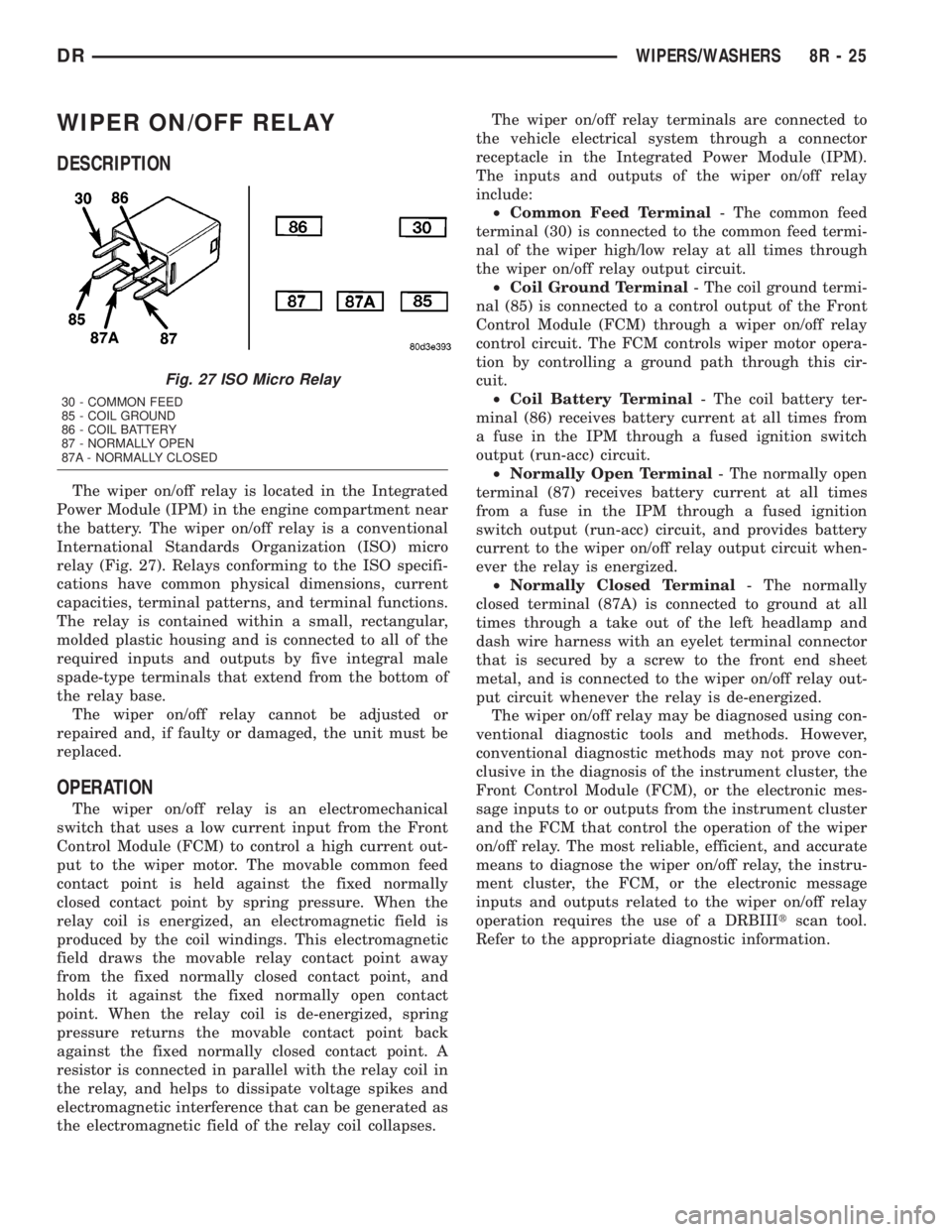
International Standards Organization (ISO) micro
relay (Fig. 27). Relays conforming to the ISO specifi-
cations have common physical dimensions, current
capacities, terminal patterns, and terminal functions.
The relay is contained within a small, rectangular,
molded plastic housing and is connected to all of the
required inputs and outputs by five integral male
spade-type terminals that extend from the bottom of
the relay base.
The wiper on/off relay cannot be adjusted or
repaired and, if faulty or damaged, the unit must be
replaced.
OPERATION
The wiper on/off relay is an electromechanical
switch that uses a low current input from the Front
Control Module (FCM) to control a high current out-
put to the wiper motor. The movable common feed
contact point is held against the fixed normally
closed contact point by spring pressure. When the
relay coil is energized, an electromagnetic field is
produced by the coil windings. This electromagnetic
field draws the movable relay contact point away
from the fixed normally closed contact point, and
holds it against the fixed normally open contact
point. When the relay coil is de-energized, spring
pressure returns the movable contact point back
against the fixed normally closed contact point. A
resistor is connected in parallel with the relay coil in
the relay, and helps to dissipate voltage spikes and
electromagnetic interference that can be generated as
the electromagnetic field of the relay coil collapses.The wiper on/off relay terminals are connected to
the vehicle electrical system through a connector
receptacle in the Integrated Power Module (IPM).
The inputs and outputs of the wiper on/off relay
include:
²Common Feed Terminal- The common feed
terminal (30) is connected to the common feed termi-
nal of the wiper high/low relay at all times through
the wiper on/off relay output circuit.
²Coil Ground Terminal- The coil ground termi-
nal (85) is connected to a control output of the Front
Control Module (FCM) through a wiper on/off relay
control circuit. The FCM controls wiper motor opera-
tion by controlling a ground path through this cir-
cuit.
²Coil Battery Terminal- The coil battery ter-
minal (86) receives battery current at all times from
a fuse in the IPM through a fused ignition switch
output (run-acc) circuit.
²Normally Open Terminal- The normally open
terminal (87) receives battery current at all times
from a fuse in the IPM through a fused ignition
switch output (run-acc) circuit, and provides battery
current to the wiper on/off relay output circuit when-
ever the relay is energized.
²Normally Closed Terminal- The normally
closed terminal (87A) is connected to ground at all
times through a take out of the left headlamp and
dash wire harness with an eyelet terminal connector
that is secured by a screw to the front end sheet
metal, and is connected to the wiper on/off relay out-
put circuit whenever the relay is de-energized.
The wiper on/off relay may be diagnosed using con-
ventional diagnostic tools and methods. However,
conventional diagnostic methods may not prove con-
clusive in the diagnosis of the instrument cluster, the
Front Control Module (FCM), or the electronic mes-
sage inputs to or outputs from the instrument cluster
and the FCM that control the operation of the wiper
on/off relay. The most reliable, efficient, and accurate
means to diagnose the wiper on/off relay, the instru-
ment cluster, the FCM, or the electronic message
inputs and outputs related to the wiper on/off relay
operation requires the use of a DRBIIItscan tool.
Refer to the appropriate diagnostic information.
Fig. 27 ISO Micro Relay
30 - COMMON FEED
85 - COIL GROUND
86 - COIL BATTERY
87 - NORMALLY OPEN
87A - NORMALLY CLOSED
DRWIPERS/WASHERS 8R - 25