ignition coil DODGE RAM 2003 Service User Guide
[x] Cancel search | Manufacturer: DODGE, Model Year: 2003, Model line: RAM, Model: DODGE RAM 2003Pages: 2895, PDF Size: 83.15 MB
Page 461 of 2895
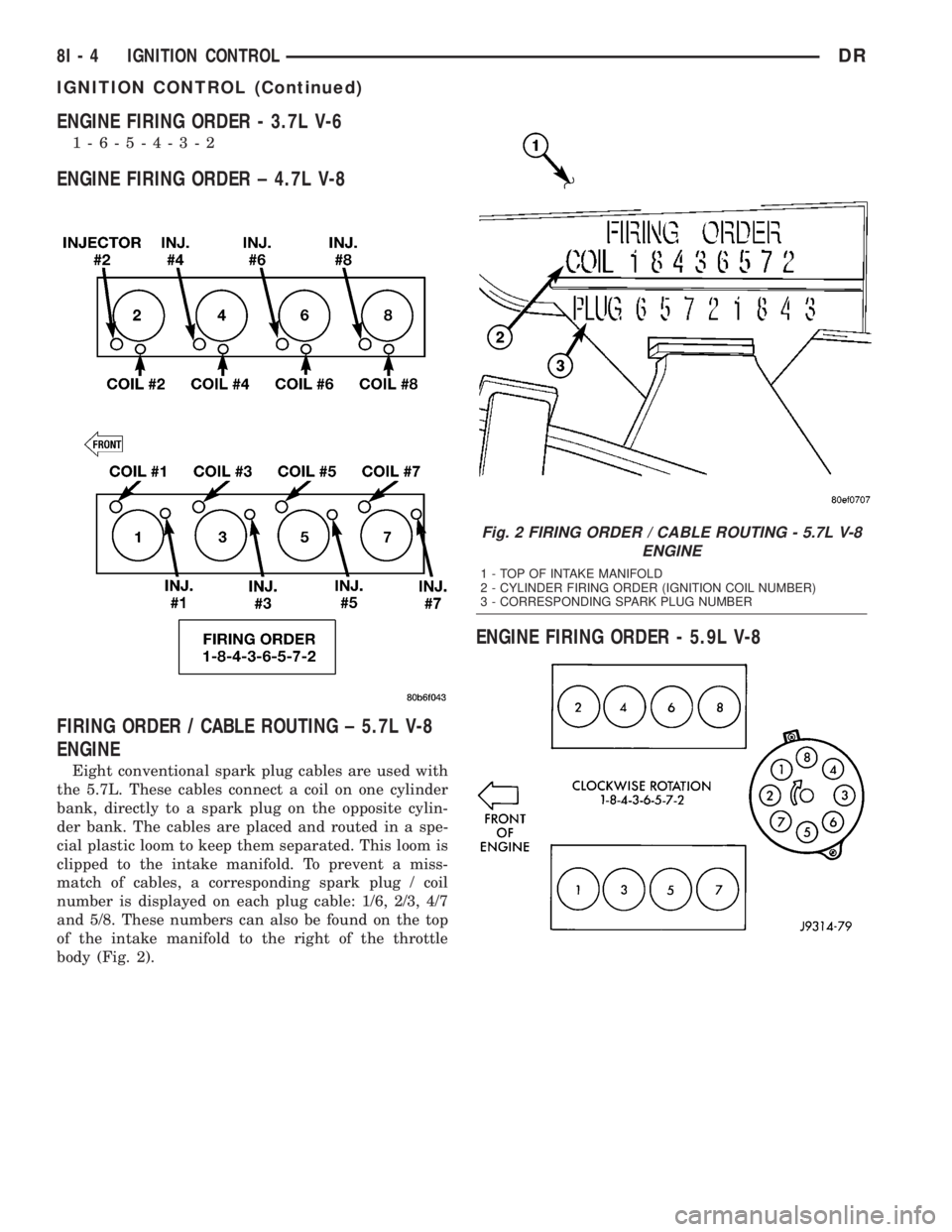
ENGINE FIRING ORDER - 3.7L V-6
1-6-5-4-3-2
ENGINE FIRING ORDER ± 4.7L V-8
FIRING ORDER / CABLE ROUTING ± 5.7L V-8
ENGINE
Eight conventional spark plug cables are used with
the 5.7L. These cables connect a coil on one cylinder
bank, directly to a spark plug on the opposite cylin-
der bank. The cables are placed and routed in a spe-
cial plastic loom to keep them separated. This loom is
clipped to the intake manifold. To prevent a miss-
match of cables, a corresponding spark plug / coil
number is displayed on each plug cable: 1/6, 2/3, 4/7
and 5/8. These numbers can also be found on the top
of the intake manifold to the right of the throttle
body (Fig. 2).
ENGINE FIRING ORDER - 5.9L V-8
Fig. 2 FIRING ORDER / CABLE ROUTING - 5.7L V-8
ENGINE
1 - TOP OF INTAKE MANIFOLD
2 - CYLINDER FIRING ORDER (IGNITION COIL NUMBER)
3 - CORRESPONDING SPARK PLUG NUMBER
8I - 4 IGNITION CONTROLDR
IGNITION CONTROL (Continued)
Page 463 of 2895
IGNITION COIL RESISTANCE - 3.7L V-6
PRIMARY RESISTANCE
21-27ÉC (70-80ÉF)SECONDARY
RESISTANCE 21-27ÉC
(70-80ÉF)
0.6 - 0.9 Ohms 6,000 - 9,000 Ohms
IGNITION COIL RESISTANCE - 4.7L V-8
PRIMARY
RESISTANCE 21-27ÉC
(70-80ÉF)SECONDARY
RESISTANCE 21-27ÉC
(70-80ÉF)
0.6 - 0.9 Ohms 6,000 - 9,000 Ohms
IGNITION COIL RESISTANCE - 5.7L V-8
PRIMARY RESISTANCE @ 21-27ÉC (70-80ÉF)
0.558 - 0.682 Ohms
(Plus or Minus 10% @ 70-80É F)
IGNITION COIL RESISTANCE - 5.9L
COIL MANUFACTURERPRIMARY RESISTANCE
21-27ÉC (70-80ÉF)SECONDARY RESISTANCE 21-27ÉC
(70-80ÉF)
Diamond 0.97 - 1.18 Ohms 11,300 - 15,300 Ohms
Toyodenso 0.95 - 1.20 Ohms 11,300 - 13,300 Ohms
IGNITION COIL RESISTANCE ± 8.0L V-10
ENGINE
Primary Resistance: 0.53-0.65 Ohms. Test across the
primary connector. Refer to text for test procedures.
Secondary Resistance: 10.9-14.7K Ohms. Test across
the individual coil towers. Refer to text for test
procedures.
IGNITION TIMING
Ignition timing is not adjustable on any engine.
AUTOMATIC SHUT DOWN
RELAY
DESCRIPTION - PCM OUTPUT
The 5±pin, 12±volt, Automatic Shutdown (ASD)
relay is located in the Power Distribution Center
(PDC). Refer to label on PDC cover for relay location.
OPERATION
OPERATION - PCM OUTPUT
The ASD relay supplies battery voltage (12+ volts)
to the fuel injectors and ignition coil(s). With certain
emissions packages it also supplies 12±volts to the
oxygen sensor heating elements.The ground circuit for the coil within the ASD
relay is controlled by the Powertrain Control Module
(PCM). The PCM operates the ASD relay by switch-
ing its ground circuit on and off.
The ASD relay will be shut±down, meaning the
12±volt power supply to the ASD relay will be de-ac-
tivated by the PCM if:
²the ignition key is left in the ON position. This
is if the engine has not been running for approxi-
mately 1.8 seconds.
²there is a crankshaft position sensor signal to
the PCM that is lower than pre-determined values.
OPERATION - ASD SENSE - PCM INPUT
A 12 volt signal at this input indicates to the PCM
that the ASD has been activated. The relay is used to
connect the oxygen sensor heater element, ignition
coil and fuel injectors to 12 volt + power supply.
This input is used only to sense that the ASD relay
is energized. If the Powertrain Control Module
(PCM) does not see 12 volts at this input when the
ASD should be activated, it will set a Diagnostic
Trouble Code (DTC).
8I - 6 IGNITION CONTROLDR
IGNITION CONTROL (Continued)
Page 464 of 2895
DIAGNOSIS AND TESTING - ASD AND FUEL
PUMP RELAYS
The following description of operation and
tests apply only to the Automatic Shutdown
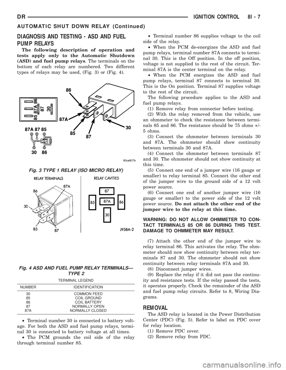
(ASD) and fuel pump relays. The terminals on the
bottom of each relay are numbered. Two different
types of relays may be used, (Fig. 3) or (Fig. 4).
²Terminal number 30 is connected to battery volt-
age. For both the ASD and fuel pump relays, termi-
nal 30 is connected to battery voltage at all times.
²The PCM grounds the coil side of the relay
through terminal number 85.²Terminal number 86 supplies voltage to the coil
side of the relay.
²When the PCM de-energizes the ASD and fuel
pump relays, terminal number 87A connects to termi-
nal 30. This is the Off position. In the off position,
voltage is not supplied to the rest of the circuit. Ter-
minal 87A is the center terminal on the relay.
²When the PCM energizes the ASD and fuel
pump relays, terminal 87 connects to terminal 30.
This is the On position. Terminal 87 supplies voltage
to the rest of the circuit.
The following procedure applies to the ASD and
fuel pump relays.
(1) Remove relay from connector before testing.
(2) With the relay removed from the vehicle, use
an ohmmeter to check the resistance between termi-
nals 85 and 86. The resistance should be 75 ohms +/-
5 ohms.
(3) Connect the ohmmeter between terminals 30
and 87A. The ohmmeter should show continuity
between terminals 30 and 87A.
(4) Connect the ohmmeter between terminals 87
and 30. The ohmmeter should not show continuity at
this time.
(5) Connect one end of a jumper wire (16 gauge or
smaller) to relay terminal 85. Connect the other end
of the jumper wire to the ground side of a 12 volt
power source.
(6) Connect one end of another jumper wire (16
gauge or smaller) to the power side of the 12 volt
power source.Do not attach the other end of the
jumper wire to the relay at this time.
WARNING: DO NOT ALLOW OHMMETER TO CON-
TACT TERMINALS 85 OR 86 DURING THIS TEST.
DAMAGE TO OHMMETER MAY RESULT.
(7) Attach the other end of the jumper wire to
relay terminal 86. This activates the relay. The ohm-
meter should now show continuity between relay ter-
minals 87 and 30. The ohmmeter should not show
continuity between relay terminals 87A and 30.
(8) Disconnect jumper wires.
(9) Replace the relay if it did not pass the continu-
ity and resistance tests. If the relay passed the tests,
it operates properly. Check the remainder of the ASD
and fuel pump relay circuits. Refer to 8, Wiring Dia-
grams.
REMOVAL
The ASD relay is located in the Power Distribution
Center (PDC) (Fig. 5). Refer to label on PDC cover
for relay location.
(1) Remove PDC cover.
(2) Remove relay from PDC.
Fig. 3 TYPE 1 RELAY (ISO MICRO RELAY)
Fig. 4 ASD AND FUEL PUMP RELAY TERMINALSÐ
TYPE 2
TERMINAL LEGEND
NUMBER IDENTIFICATION
30 COMMON FEED
85 COIL GROUND
86 COIL BATTERY
87 NORMALLY OPEN
87A NORMALLY CLOSED
DRIGNITION CONTROL 8I - 7
AUTOMATIC SHUT DOWN RELAY (Continued)
Page 476 of 2895
DISTRIBUTOR ROTOR
DIAGNOSIS AND TESTING - DISTRIBUTOR
ROTOR - 5.9L V-8
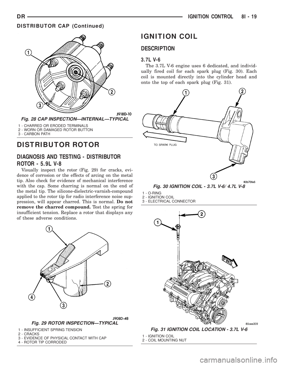
Visually inspect the rotor (Fig. 29) for cracks, evi-
dence of corrosion or the effects of arcing on the metal
tip. Also check for evidence of mechanical interference
with the cap. Some charring is normal on the end of
the metal tip. The silicone-dielectric-varnish-compound
applied to the rotor tip for radio interference noise sup-
pression, will appear charred. This is normal.Do not
remove the charred compound.
Test the spring for
insufficient tension. Replace a rotor that displays any
of these adverse conditions.
IGNITION COIL
DESCRIPTION
3.7L V-6
The 3.7L V-6 engine uses 6 dedicated, and individ-
ually fired coil for each spark plug (Fig. 30). Each
coil is mounted directly into the cylinder head and
onto the top of each spark plug (Fig. 31).
Fig. 28 CAP INSPECTIONÐINTERNALÐTYPICAL
1 - CHARRED OR ERODED TERMINALS
2 - WORN OR DAMAGED ROTOR BUTTON
3 - CARBON PATH
Fig. 29 ROTOR INSPECTIONÐTYPICAL
1 - INSUFFICIENT SPRING TENSION
2 - CRACKS
3 - EVIDENCE OF PHYSICAL CONTACT WITH CAP
4 - ROTOR TIP CORRODED
Fig. 30 IGNITION COIL - 3.7L V-6/ 4.7L V-8
1 - O-RING
2 - IGNITION COIL
3 - ELECTRICAL CONNECTOR
Fig. 31 IGNITION COIL LOCATION - 3.7L V-6
1 - IGNITION COIL
2 - COIL MOUNTING NUT
DRIGNITION CONTROL 8I - 19
DISTRIBUTOR CAP (Continued)
Page 477 of 2895
4.7L V-8
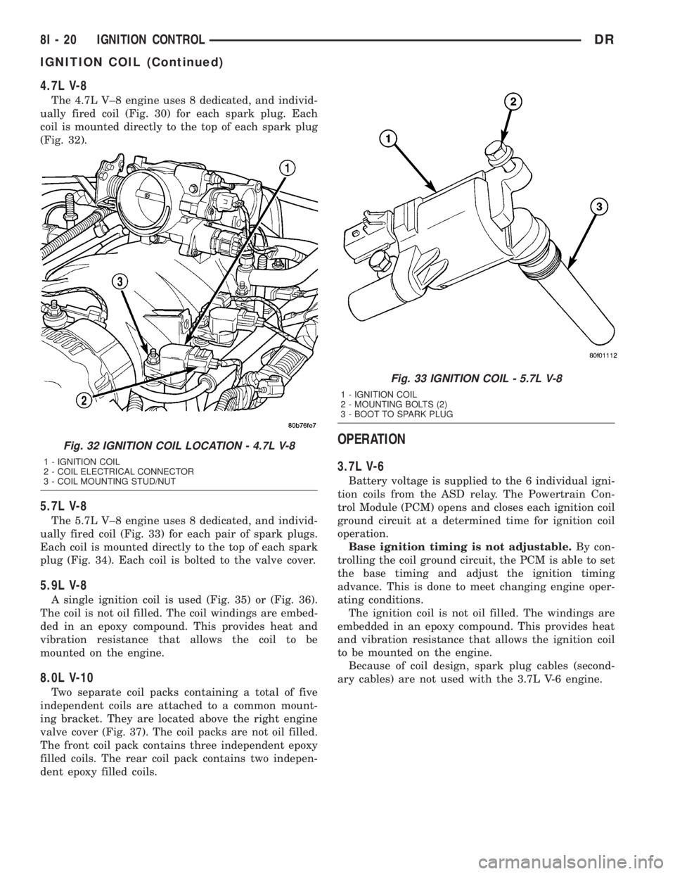
The 4.7L V±8 engine uses 8 dedicated, and individ-
ually fired coil (Fig. 30) for each spark plug. Each
coil is mounted directly to the top of each spark plug
(Fig. 32).
5.7L V-8
The 5.7L V±8 engine uses 8 dedicated, and individ-
ually fired coil (Fig. 33) for each pair of spark plugs.
Each coil is mounted directly to the top of each spark
plug (Fig. 34). Each coil is bolted to the valve cover.
5.9L V-8
A single ignition coil is used (Fig. 35) or (Fig. 36).
The coil is not oil filled. The coil windings are embed-
ded in an epoxy compound. This provides heat and
vibration resistance that allows the coil to be
mounted on the engine.
8.0L V-10
Two separate coil packs containing a total of five
independent coils are attached to a common mount-
ing bracket. They are located above the right engine
valve cover (Fig. 37). The coil packs are not oil filled.
The front coil pack contains three independent epoxy
filled coils. The rear coil pack contains two indepen-
dent epoxy filled coils.
OPERATION
3.7L V-6
Battery voltage is supplied to the 6 individual igni-
tion coils from the ASD relay. The Powertrain Con-
trol Module (PCM) opens and closes each ignition coil
ground circuit at a determined time for ignition coil
operation.
Base ignition timing is not adjustable.By con-
trolling the coil ground circuit, the PCM is able to set
the base timing and adjust the ignition timing
advance. This is done to meet changing engine oper-
ating conditions.
The ignition coil is not oil filled. The windings are
embedded in an epoxy compound. This provides heat
and vibration resistance that allows the ignition coil
to be mounted on the engine.
Because of coil design, spark plug cables (second-
ary cables) are not used with the 3.7L V-6 engine.
Fig. 32 IGNITION COIL LOCATION - 4.7L V-8
1 - IGNITION COIL
2 - COIL ELECTRICAL CONNECTOR
3 - COIL MOUNTING STUD/NUT
Fig. 33 IGNITION COIL - 5.7L V-8
1 - IGNITION COIL
2 - MOUNTING BOLTS (2)
3 - BOOT TO SPARK PLUG
8I - 20 IGNITION CONTROLDR
IGNITION COIL (Continued)
Page 478 of 2895
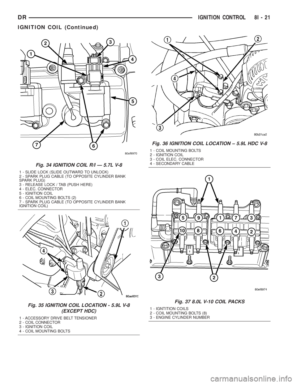
Fig. 34 IGNITION COIL R/I Ð 5.7L V-8
1 - SLIDE LOCK (SLIDE OUTWARD TO UNLOCK)
2 - SPARK PLUG CABLE (TO OPPOSITE CYLINDER BANK
SPARK PLUG)
3 - RELEASE LOCK / TAB (PUSH HERE)
4 - ELEC. CONNECTOR
5 - IGNITION COIL
6 - COIL MOUNTING BOLTS (2)
7 - SPARK PLUG CABLE (TO OPPOSITE CYLINDER BANK
IGNITION COIL)
Fig. 35 IGNITION COIL LOCATION - 5.9L V-8
(EXCEPT HDC)
1 - ACCESSORY DRIVE BELT TENSIONER
2 - COIL CONNECTOR
3 - IGNITION COIL
4 - COIL MOUNTING BOLTS
Fig. 36 IGNITION COIL LOCATION ± 5.9L HDC V-8
1 - COIL MOUNTING BOLTS
2 - IGNITION COIL
3 - COIL ELEC. CONNECTOR
4 - SECONDARY CABLE
Fig. 37 8.0L V-10 COIL PACKS
1 - IGNTITION COILS
2 - COIL MOUNTING BOLTS (8)
3 - ENGINE CYLINDER NUMBER
DRIGNITION CONTROL 8I - 21
IGNITION COIL (Continued)
Page 479 of 2895
4.7L V-8
Battery voltage is supplied to the 8 individual igni-
tion coils from the ASD relay. The Powertrain Con-
trol Module (PCM) opens and closes each ignition coil
ground circuit at a determined time for ignition coil
operation.
Base ignition timing is not adjustable.By con-
trolling the coil ground circuit, the PCM is able to set
the base timing and adjust the ignition timing
advance. This is done to meet changing engine oper-
ating conditions.
The ignition coil is not oil filled. The windings are
embedded in an epoxy compound. This provides heat
and vibration resistance that allows the ignition coil
to be mounted on the engine.
Because of coil design, spark plug cables (second-
ary cables) are not used with the 4.7L V-8 engine.
5.7L V-8
The ignition system is controlled by the Powertrain
Control Module (PCM) on all engines.
A ªwasted sparkº system is used on the 5.7L
engine combining paired, or dual-firing coils, and 2
spark plugs per cylinder. The coils and spark plugs
are connected with paired, secondary high-voltage
cables.
Each cylinder is equipped with 1 dual-output coil.
Meaning one coil mounts directly over one of the
dual spark plugs for 1 high-voltage output. A second
high-voltage output is supplied directly from the
same coil (using a plug cable) to one of the dual
spark plugs on a corresponding (paired) cylinder on
the opposite cylinder bank.
Each coil fires 2 spark plugs simultaneously on
each of the cylinder banks (one cylinder on compres-
sion stroke and one cylinder on exhaust stroke).
EXAMPLE :When the #1 cylinder is on compression
stroke and ready for spark, the #1 coil will fire one of
the dual spark plugs on the #1 cylinder (directly
below the coil). The other dual spark plug on the #1
cylinder will be fired by the #6 coil. At the same
time, the #1 coil will fire a ªwasted sparkº to one of
the dual spark plugs at the #6 cylinder as coil #6 also
fires a ªwasted sparkº to one of the dual spark plugs
at the #6 cylinder.
The firing order is paired at cylinders 1/6, 2/3, 4/7,
5/8. Basic cylinder firing order is 1±8±4±3±6±5±7±2.
Battery voltage is supplied to all of the ignition
coils positive terminals from the ASD relay. If the
PCM does not see a signal from the crankshaft and
camshaft sensors (indicating the ignition key is ON
but the engine is not running), it will shut down the
ASD circuit.
Base ignition timing is not adjustable on the
5.7L V-8 engine.By controlling the coil ground cir-
cuits, the PCM is able to set the base timing andadjust the ignition timing advance. This is done to
meet changing engine operating conditions.
The PCM adjusts ignition timing based on inputs it
receives from:
²The engine coolant temperature sensor
²The crankshaft position sensor (engine speed)
²The camshaft position sensor (crankshaft posi-
tion)
²The manifold absolute pressure (MAP) sensor
²The throttle position sensor
²Transmission gear selection
5.9L V-8
A single ignition coil is used. The Powertrain Con-
trol Module (PCM) opens and closes the ignition coil
ground circuit for ignition coil operation.
Battery voltage is supplied to the ignition coil pos-
itive terminal from the ASD relay. If the PCM does
not see a signal from the crankshaft and camshaft
sensors (indicating the ignition key is ON but the
engine is not running), it will shut down the ASD cir-
cuit.
Base ignition timing is not adjustable on any
engine.By controlling the coil ground circuit, the
PCM is able to set the base timing and adjust the
ignition timing advance. This is done to meet chang-
ing engine operating conditions.
Conventional spark plug cables (secondary cables)
are used with the 5.9L V-8 engine.
8.0L V-10
When one of the 5 independent coils discharges, it
fires two paired cylinders at the same time (one cyl-
inder on compression stroke and the other cylinder
on exhaust stroke).
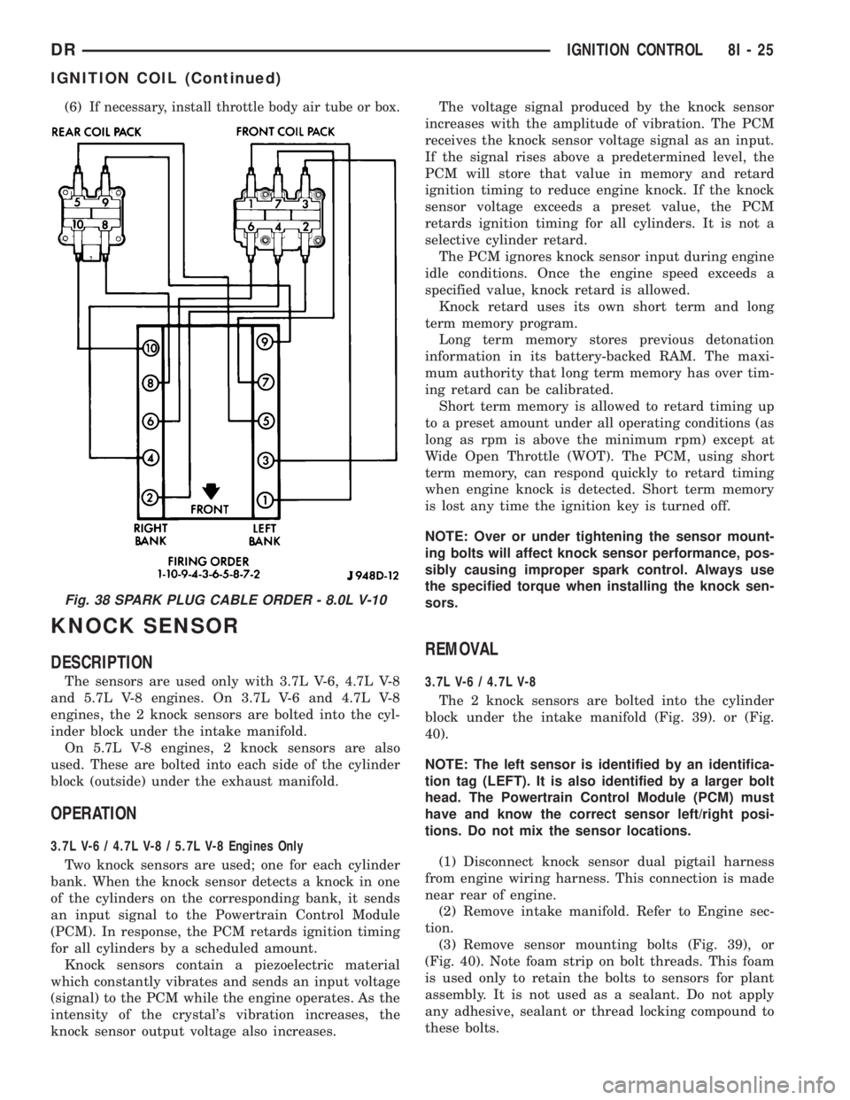
Coil firing is paired together on cylinders:
²Number 5 and 10
²Number 9 and 8
²Number 1 and 6
²Number 7 and 4
²Number 3 and 2
The ignition system is controlled by the Powertrain
Control Module (PCM) on all engines.
Battery voltage is supplied to all of the ignition
coils positive terminals from the ASD relay. If the
PCM does not see a signal from the crankshaft and
camshaft sensors (indicating the ignition key is ON
but the engine is not running), it will shut down the
ASD circuit.
Conventional spark plug cables (secondary cables)
are used with the 8.0L V-10 engine.
Base ignition timing is not adjustable on the
8.0L V-10 engine.By controlling the coil ground cir-
cuits, the PCM is able to set the base timing and
adjust the ignition timing advance. This is done to
meet changing engine operating conditions.
8I - 22 IGNITION CONTROLDR
IGNITION COIL (Continued)
Page 480 of 2895
The PCM adjusts ignition timing based on inputs it
receives from:
²The engine coolant temperature sensor
²The crankshaft position sensor (engine speed)
²The camshaft position sensor (crankshaft posi-
tion)
²The manifold absolute pressure (MAP) sensor
²The throttle position sensor
²Transmission gear selection
REMOVAL
3.7L V-6
An individual ignition coil is used for each spark
plug (Fig. 30). The coil fits into machined holes in the
cylinder head. A mounting stud/nut secures each coil
to the top of the intake manifold (Fig. 31). The bot-
tom of the coil is equipped with a rubber boot to seal
the spark plug to the coil. Inside each rubber boot is
a spring. The spring is used for a mechanical contact
between the coil and the top of the spark plug. These
rubber boots and springs are a permanent part of the
coil and are not serviced separately. An o-ring (Fig.
30) is used to seal the coil at the opening into the cyl-
inder head.
(1) Depending on which coil is being removed, the
throttle body air intake tube or intake box may need
to be removed to gain access to coil.
(2) Disconnect electrical connector from coil by
pushing downward on release lock on top of connec-
tor and pull connector from coil.
(3) Clean area at base of coil with compressed air
before removal.
(4) Remove coil mounting nut from mounting stud
(Fig. 31).
(5) Carefully pull up coil from cylinder head open-
ing with a slight twisting action.
(6) Remove coil from vehicle.
4.7L V-8
An individual ignition coil is used for each spark
plug (Fig. 30). The coil fits into machined holes in the
cylinder head. A mounting stud/nut secures each coil
to the top of the intake manifold (Fig. 32). The bot-
tom of the coil is equipped with a rubber boot to seal
the spark plug to the coil. Inside each rubber boot is
a spring. The spring is used for a mechanical contact
between the coil and the top of the spark plug. These
rubber boots and springs are a permanent part of the
coil and are not serviced separately. An o-ring (Fig.
30) is used to seal the coil at the opening into the cyl-
inder head.
(1) Depending on which coil is being removed, the
throttle body air intake tube or intake box may need
to be removed to gain access to coil.(2) Disconnect electrical connector (Fig. 32) from
coil by pushing downward on release lock on top of
connector and pull connector from coil.
(3) Clean area at base of coil with compressed air
before removal.
(4) Remove coil mounting nut from mounting stud
(Fig. 32).
(5) Carefully pull up coil from cylinder head open-
ing with a slight twisting action.
(6) Remove coil from vehicle.
5.7L V-8
Before removing or disconnecting any spark plug
cables, note their original position. Remove cables
one-at-a-time. To prevent ignition crossfire, spark
plug cablesMUSTbe placed in cable tray (routing
loom) into their original position.
An individual ignition coil (Fig. 33) is used at each
cylinder. The coil mounts to the top of the valve cover
with 2 bolts (Fig. 34). The bottom of the coil is
equipped with a rubber boot to seal the spark plug to
the coil. Inside each rubber boot is a spring. The
spring is used for a mechanical contact between the
coil and the top of the spark plug.
(1) Depending on which coil is being removed, the
throttle body air intake tube or intake box may need
to be removed to gain access to coil.
(2) Unlock electrical connector (Fig. 34) by moving
slide lock first. Press on release lock (Fig. 34) while
pulling electrical connector from coil.
(3) Disconnect secondary high-voltage cable from
coil with a twisting action.
(4) Clean area at base of coil with compressed air
before removal.
(5) Remove 2 mounting bolts (note that mounting
bolts are retained to coil).
(6) Carefully pull up coil from cylinder head open-
ing with a slight twisting action.
(7) Remove coil from vehicle.
(8) Before installing spark plug cables to either the
spark plugs or coils, or before installing a coil to a
spark plug, apply dielectric grease to inside of boots.
5.9L V-8
The coil is not oil filled. The coil windings are
embedded in an epoxy compound. This provides heat
and vibration resistance that allows the coil to be
mounted on the engine. If the coil is replaced, it must
be replaced with the same type.
5.9L V-8 LDC-Gas Engines: The coil is mounted to
a bracket that is bolted to the front of the right
engine cylinder head (Fig. 35). This bracket is
mounted on top of the automatic belt tensioner
bracket using common bolts.
DRIGNITION CONTROL 8I - 23
IGNITION COIL (Continued)
Page 481 of 2895
WARNING: 5.9L V-8 LDC-GAS ENGINES: DO NOT
REMOVE THE COIL MOUNTING BRACKET-TO-CYL-
INDER HEAD MOUNTING BOLTS. THE COIL
MOUNTING BRACKET IS UNDER ACCESSORY
DRIVE BELT TENSION. IF THIS BRACKET IS TO BE
REMOVED FOR ANY REASON, ALL BELT TENSION
MUST FIRST BE RELIEVED. REFER TO THE BELT
SECTION OF GROUP 7, COOLING SYSTEM.
5.9L V-8 HDC-Gas Engine: The coil is mounted to
a bracket that is bolted to the air injection pump
(AIR pump) mounting bracket (Fig. 36).
(1) Disconnect primary coil connector from ignition
coil.
(2) Disconnect secondary cable from ignition coil.
(3) Remove ignition coil from coil mounting
bracket (two bolts).
8.0L V-10
Two separate coil packs containing a total of five
independent coils are attached to a common mount-
ing bracket located above the right engine valve
cover (Fig. 37). The front and rear coil packs can be
serviced separately.
(1) Depending on which coil is being removed, the
throttle body air intake tube or intake box may need
to be removed to gain access to coils.
(2) Remove secondary spark plug cables from coil
packs. Note position of cables before removal.
(3) Disconnect primary wiring harness connectors
at coil packs.
(4) Remove four (4) coil pack-to-coil mounting
bracket bolts for coil pack being serviced (Fig. 37).
(5) Remove coil(s) from mounting bracket.
INSTALLATION
3.7L V-6
(1) Using compressed air, blow out any dirt or con-
taminants from around top of spark plug.
(2) Check condition of coil o-ring and replace as
necessary. To aid in coil installation, apply silicone to
coil o-ring.
(3) Position ignition coil into cylinder head opening
and push onto spark plug. Do this while guiding coil
base over mounting stud.
(4) Install coil mounting stud nut. Refer to torque
specifications.
(5) Connect electrical connector to coil by snapping
into position.
(6) If necessary, install throttle body air tube.
4.7L V-8
(1) Using compressed air, blow out any dirt or con-
taminants from around top of spark plug.
(2) Check condition of coil o-ring and replace as
necessary. To aid in coil installation, apply silicone to
coil o-ring.
(3) Position ignition coil into cylinder head opening
and push onto spark plug. Do this while guiding coil
base over mounting stud.
(4) Install coil mounting stud nut. Refer to torque
specifications.
(5) Connect electrical connector to coil by snapping
into position.
(6) If necessary, install throttle body air tube.
5.7L V-8
(1) Using compressed air, blow out any dirt or con-
taminants from around top of spark plug.
(2) Before installing spark plug cables to either the
spark plugs or coils, or before installing a coil to a
spark plug, apply dielectric grease to inside of boots.
(3) Position ignition coil into cylinder head opening
and push onto spark plug. Twist coil into position.
(4) Install 2 coil mounting bolts. Refer to torque
specifications.
(5) Connect electrical connector to coil by snapping
into position.
(6) Install cable to coil. To prevent ignition cross-
fire, spark plug cablesMUSTbe placed in cable tray
(routing loom) into their original position. Refer to
Spark Plug Cable Removal for a graphic.
(7) If necessary, install throttle body air tube.
5.9L V-8
The ignition coil is an epoxy filled type. If the coil
is replaced, it must be replaced with the same type.
(1) Install ignition coil to coil bracket. If nuts and
bolts are used to secure coil to coil bracket, tighten to
11 N´m (100 in. lbs.) torque. If coil mounting bracket
has been tapped for coil mounting bolts, tighten bolts
to 5 N´m (50 in. lbs.) torque.
(2) Connect all wiring to ignition coil.
8.0L V-10
(1) Position coil packs to mounting bracket (prima-
ry wiring connectors face downward).
(2) Install coil pack mounting bolts. Tighten bolts
to 10 N´m (90 in. lbs.) torque.
(3) Install coil pack-to-engine mounting bracket (if
necessary).
(4) Connect primary wiring connectors to coil
packs (four wire connector to front coil pack and
three wire connector to rear coil pack).
(5) Connect secondary spark plug cables to coil
packs. Refer to (Fig. 38) for correct cable order.
8I - 24 IGNITION CONTROLDR
IGNITION COIL (Continued)
Page 482 of 2895
(6)If necessary, install throttle body air tube or box.
KNOCK SENSOR
DESCRIPTION
The sensors are used only with 3.7L V-6, 4.7L V-8
and 5.7L V-8 engines. On 3.7L V-6 and 4.7L V-8
engines, the 2 knock sensors are bolted into the cyl-
inder block under the intake manifold.
On 5.7L V-8 engines, 2 knock sensors are also
used. These are bolted into each side of the cylinder
block (outside) under the exhaust manifold.
OPERATION
3.7L V-6 / 4.7L V-8 / 5.7L V-8 Engines Only
Two knock sensors are used; one for each cylinder
bank. When the knock sensor detects a knock in one
of the cylinders on the corresponding bank, it sends
an input signal to the Powertrain Control Module
(PCM). In response, the PCM retards ignition timing
for all cylinders by a scheduled amount.
Knock sensors contain a piezoelectric material
which constantly vibrates and sends an input voltage
(signal) to the PCM while the engine operates. As the
intensity of the crystal's vibration increases, the
knock sensor output voltage also increases.The voltage signal produced by the knock sensor
increases with the amplitude of vibration. The PCM
receives the knock sensor voltage signal as an input.
If the signal rises above a predetermined level, the
PCM will store that value in memory and retard
ignition timing to reduce engine knock. If the knock
sensor voltage exceeds a preset value, the PCM
retards ignition timing for all cylinders. It is not a
selective cylinder retard.
The PCM ignores knock sensor input during engine
idle conditions. Once the engine speed exceeds a
specified value, knock retard is allowed.
Knock retard uses its own short term and long
term memory program.
Long term memory stores previous detonation
information in its battery-backed RAM. The maxi-
mum authority that long term memory has over tim-
ing retard can be calibrated.
Short term memory is allowed to retard timing up
to a preset amount under all operating conditions (as
long as rpm is above the minimum rpm) except at
Wide Open Throttle (WOT). The PCM, using short
term memory, can respond quickly to retard timing
when engine knock is detected. Short term memory
is lost any time the ignition key is turned off.
NOTE: Over or under tightening the sensor mount-
ing bolts will affect knock sensor performance, pos-
sibly causing improper spark control. Always use
the specified torque when installing the knock sen-
sors.
REMOVAL
3.7L V-6 / 4.7L V-8
The 2 knock sensors are bolted into the cylinder
block under the intake manifold (Fig. 39). or (Fig.
40).
NOTE: The left sensor is identified by an identifica-
tion tag (LEFT). It is also identified by a larger bolt
head. The Powertrain Control Module (PCM) must
have and know the correct sensor left/right posi-
tions. Do not mix the sensor locations.
(1) Disconnect knock sensor dual pigtail harness
from engine wiring harness. This connection is made
near rear of engine.
(2) Remove intake manifold. Refer to Engine sec-
tion.
(3) Remove sensor mounting bolts (Fig. 39), or
(Fig. 40). Note foam strip on bolt threads. This foam
is used only to retain the bolts to sensors for plant
assembly. It is not used as a sealant. Do not apply
any adhesive, sealant or thread locking compound to
these bolts.
Fig. 38 SPARK PLUG CABLE ORDER - 8.0L V-10
DRIGNITION CONTROL 8I - 25
IGNITION COIL (Continued)