Engine DODGE RAM 2003 Service Owner's Guide
[x] Cancel search | Manufacturer: DODGE, Model Year: 2003, Model line: RAM, Model: DODGE RAM 2003Pages: 2895, PDF Size: 83.15 MB
Page 136 of 2895
ASSEMBLY
NOTE: If the same gears and thrust washers are
being used, install them into their orignial locations.
(1) Lubricate all differential components with axle
lubricant.
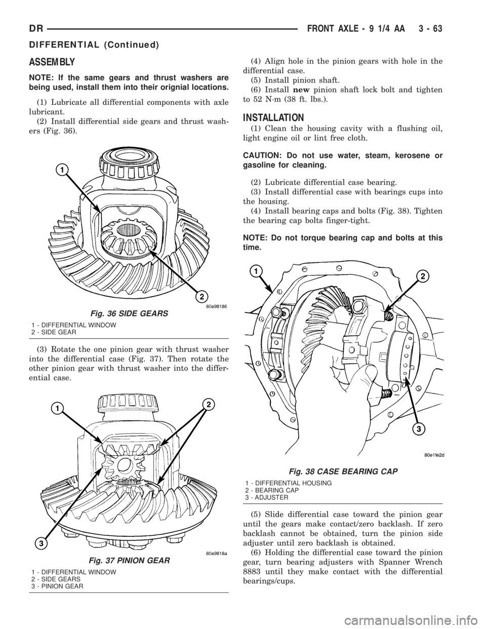
(2) Install differential side gears and thrust wash-
ers (Fig. 36).
(3) Rotate the one pinion gear with thrust washer
into the differential case (Fig. 37). Then rotate the
other pinion gear with thrust washer into the differ-
ential case.(4) Align hole in the pinion gears with hole in the
differential case.
(5) Install pinion shaft.
(6) Installnewpinion shaft lock bolt and tighten
to 52 N´m (38 ft. lbs.).
INSTALLATION
(1) Clean the housing cavity with a flushing oil,
light engine oil or lint free cloth.
CAUTION: Do not use water, steam, kerosene or
gasoline for cleaning.
(2) Lubricate differential case bearing.
(3) Install differential case with bearings cups into
the housing.
(4) Install bearing caps and bolts (Fig. 38). Tighten
the bearing cap bolts finger-tight.
NOTE: Do not torque bearing cap and bolts at this
time.
(5) Slide differential case toward the pinion gear
until the gears make contact/zero backlash. If zero
backlash cannot be obtained, turn the pinion side
adjuster until zero backlash is obtained.
(6) Holding the differential case toward the pinion
gear, turn bearing adjusters with Spanner Wrench
8883 until they make contact with the differential
bearings/cups.
Fig. 36 SIDE GEARS
1 - DIFFERENTIAL WINDOW
2 - SIDE GEAR
Fig. 37 PINION GEAR
1 - DIFFERENTIAL WINDOW
2 - SIDE GEARS
3 - PINION GEAR
Fig. 38 CASE BEARING CAP
1 - DIFFERENTIAL HOUSING
2 - BEARING CAP
3 - ADJUSTER
DRFRONT AXLE - 9 1/4 AA 3 - 63
DIFFERENTIAL (Continued)
Page 142 of 2895
REAR AXLE-91/4
TABLE OF CONTENTS
page page
REAR AXLE-91/4
DESCRIPTION.........................69
OPERATION...........................69
DIAGNOSIS AND TESTING................69
REMOVAL.............................74
INSTALLATION.........................74
ADJUSTMENTS........................74
SPECIFICATIONS.......................79
SPECIAL TOOLS.......................80
AXLE SHAFTS
REMOVAL.............................83
INSTALLATION.........................83
AXLE SHAFT SEALS
REMOVAL.............................84
INSTALLATION.........................84
AXLE BEARINGS
REMOVAL.............................84
INSTALLATION.........................84
PINION SEAL
REMOVAL.............................85INSTALLATION.........................85
DIFFERENTIAL
DESCRIPTION.........................86
OPERATION...........................86
REMOVAL.............................86
DISASSEMBLY.........................88
ASSEMBLY............................88
INSTALLATION.........................88
DIFFERENTIAL-TRAC-LOK
DESCRIPTION.........................89
OPERATION...........................89
DIAGNOSIS AND TESTING................89
DISASSEMBLY.........................90
ASSEMBLY............................92
DIFFERENTIAL CASE BEARINGS
REMOVAL.............................93
INSTALLATION.........................94
PINION GEAR/RING GEAR/TONE RING
REMOVAL.............................94
INSTALLATION.........................96
REAR AXLE-91/4
DESCRIPTION
The axle consist of a cast iron center section with
axle tubes extending from either side. The tubes are
pressed into and welded to the differential housing to
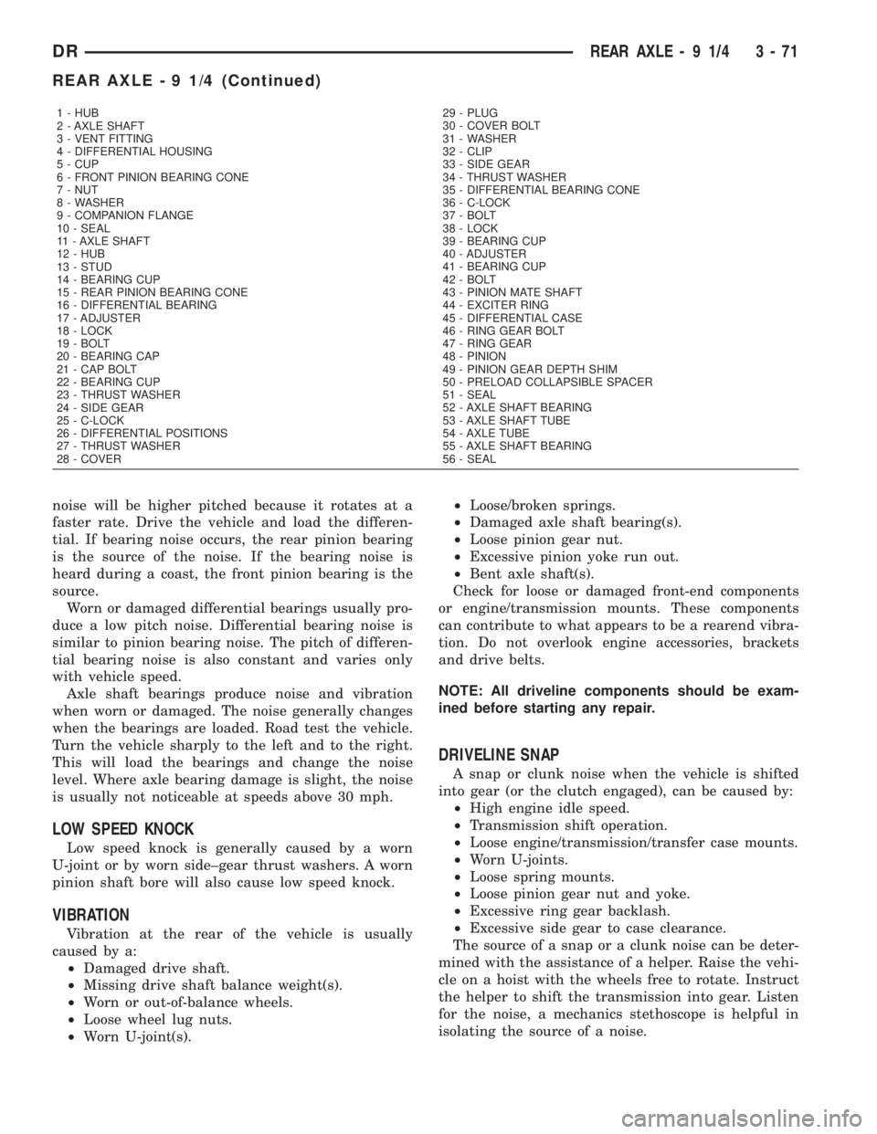
form a one-piece axle housing (Fig. 1). The axles are
equipped with semi-floating axle shafts, meaning
vehicle loads are supported by the axle shaft and
bearings. The axle shafts are retained by C-locks in
the differential side gears.
OPERATION
The axle receives power from the propeller shaft.
The propeller shaft is connected to the pinion gear
which rotates the differential through the gear mesh
with the ring gear bolted to the differential case. The
engine power is transmitted to the axle shafts
through the pinion mate and side gears. The side
gears are splined to the axle shafts.
DIAGNOSIS AND TESTING
GEAR NOISE
Axle gear noise can be caused by insufficient lubri-
cant, incorrect backlash, incorrect pinion depth, toothcontact, worn/damaged gears, or the carrier housing
not having the proper offset and squareness.
Gear noise usually happens at a specific speed
range. The noise can also occur during a specific type
of driving condition. These conditions are accelera-
tion, deceleration, coast, or constant load.
When road testing, first warm-up the axle fluid by
driving the vehicle at least 5 miles and then acceler-
ate the vehicle to the speed range where the noise is
the greatest. Shift out-of-gear and coast through the
peak-noise range. If the noise stops or changes
greatly:
²Check for insufficient lubricant.
²Incorrect ring gear backlash.
²Gear damage.
Differential side gears and pinions can be checked
by turning the vehicle. They usually do not cause
noise during straight-ahead driving when the gears
are unloaded. The side gears are loaded during vehi-
cle turns. A worn pinion shaft can also cause a snap-
ping or a knocking noise.
BEARING NOISE
The axle shaft, differential and pinion bearings can
all produce noise when worn or damaged. Bearing
noise can be either a whining, or a growling sound.
Pinion bearings have a constant-pitch noise. This
noise changes only with vehicle speed. Pinion bearing
DRREAR AXLE - 9 1/4 3 - 69
Page 144 of 2895
noise will be higher pitched because it rotates at a
faster rate. Drive the vehicle and load the differen-
tial. If bearing noise occurs, the rear pinion bearing
is the source of the noise. If the bearing noise is
heard during a coast, the front pinion bearing is the
source.
Worn or damaged differential bearings usually pro-
duce a low pitch noise. Differential bearing noise is
similar to pinion bearing noise. The pitch of differen-
tial bearing noise is also constant and varies only
with vehicle speed.
Axle shaft bearings produce noise and vibration
when worn or damaged. The noise generally changes
when the bearings are loaded. Road test the vehicle.
Turn the vehicle sharply to the left and to the right.
This will load the bearings and change the noise
level. Where axle bearing damage is slight, the noise
is usually not noticeable at speeds above 30 mph.
LOW SPEED KNOCK
Low speed knock is generally caused by a worn
U-joint or by worn side±gear thrust washers. A worn
pinion shaft bore will also cause low speed knock.
VIBRATION
Vibration at the rear of the vehicle is usually
caused by a:
²Damaged drive shaft.
²Missing drive shaft balance weight(s).
²Worn or out-of-balance wheels.
²Loose wheel lug nuts.
²Worn U-joint(s).²Loose/broken springs.
²Damaged axle shaft bearing(s).
²Loose pinion gear nut.
²Excessive pinion yoke run out.
²Bent axle shaft(s).
Check for loose or damaged front-end components
or engine/transmission mounts. These components
can contribute to what appears to be a rearend vibra-
tion. Do not overlook engine accessories, brackets
and drive belts.
NOTE: All driveline components should be exam-
ined before starting any repair.
DRIVELINE SNAP
A snap or clunk noise when the vehicle is shifted
into gear (or the clutch engaged), can be caused by:
²High engine idle speed.
²Transmission shift operation.
²Loose engine/transmission/transfer case mounts.
²Worn U-joints.
²Loose spring mounts.
²Loose pinion gear nut and yoke.
²Excessive ring gear backlash.
²Excessive side gear to case clearance.
The source of a snap or a clunk noise can be deter-
mined with the assistance of a helper. Raise the vehi-
cle on a hoist with the wheels free to rotate. Instruct
the helper to shift the transmission into gear. Listen
for the noise, a mechanics stethoscope is helpful in
isolating the source of a noise.
1 - HUB
2 - AXLE SHAFT
3 - VENT FITTING
4 - DIFFERENTIAL HOUSING
5 - CUP
6 - FRONT PINION BEARING CONE
7 - NUT
8 - WASHER
9 - COMPANION FLANGE
10 - SEAL
11 - AXLE SHAFT
12 - HUB
13 - STUD
14 - BEARING CUP
15 - REAR PINION BEARING CONE
16 - DIFFERENTIAL BEARING
17 - ADJUSTER
18 - LOCK
19 - BOLT
20 - BEARING CAP
21 - CAP BOLT
22 - BEARING CUP
23 - THRUST WASHER
24 - SIDE GEAR
25 - C-LOCK
26 - DIFFERENTIAL POSITIONS
27 - THRUST WASHER
28 - COVER29 - PLUG
30 - COVER BOLT
31 - WASHER
32 - CLIP
33 - SIDE GEAR
34 - THRUST WASHER
35 - DIFFERENTIAL BEARING CONE
36 - C-LOCK
37 - BOLT
38 - LOCK
39 - BEARING CUP
40 - ADJUSTER
41 - BEARING CUP
42 - BOLT
43 - PINION MATE SHAFT
44 - EXCITER RING
45 - DIFFERENTIAL CASE
46 - RING GEAR BOLT
47 - RING GEAR
48 - PINION
49 - PINION GEAR DEPTH SHIM
50 - PRELOAD COLLAPSIBLE SPACER
51 - SEAL
52 - AXLE SHAFT BEARING
53 - AXLE SHAFT TUBE
54 - AXLE TUBE
55 - AXLE SHAFT BEARING
56 - SEAL
DRREAR AXLE - 9 1/4 3 - 71
REAR AXLE - 9 1/4 (Continued)
Page 160 of 2895
(2) Remove differential cover and drain the lubri-
cant.
(3) Clean housing cavity with flushing oil, light
engine oil or a lint free cloth.
NOTE: Do not use steam, kerosene or gasoline to
clean the housing.
(4) Remove axle shafts.
(5) Remove RWAL/ABS sensor from housing.
NOTE: Side play resulting from bearing races being
loose on case hubs requires replacement of the dif-
ferential case.
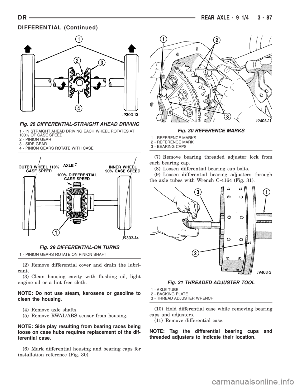
(6) Mark differential housing and bearing caps for
installation reference (Fig. 30).(7) Remove bearing threaded adjuster lock from
each bearing cap.
(8) Loosen differential bearing cap bolts.
(9) Loosen differential bearing adjusters through
the axle tubes with Wrench C-4164 (Fig. 31).
(10) Hold differential case while removing bearing
caps and adjusters.
(11) Remove differential case.
NOTE: Tag the differential bearing cups and
threaded adjusters to indicate their location.
Fig. 28 DIFFERENTIAL-STRAIGHT AHEAD DRIVING
1 - IN STRAIGHT AHEAD DRIVING EACH WHEEL ROTATES AT
100% OF CASE SPEED
2 - PINION GEAR
3 - SIDE GEAR
4 - PINION GEARS ROTATE WITH CASE
Fig. 29 DIFFERENTIAL-ON TURNS
1 - PINION GEARS ROTATE ON PINION SHAFT
Fig. 30 REFERENCE MARKS
1 - REFERENCE MARKS
2 - REFERENCE MARK
3 - BEARING CAPS
Fig. 31 THREADED ADJUSTER TOOL
1 - AXLE TUBE
2 - BACKING PLATE
3 - THREAD ADJUSTER WRENCH
DRREAR AXLE - 9 1/4 3 - 87
DIFFERENTIAL (Continued)
Page 163 of 2895
(friction modifier) should be added after repair ser-
vice or during a lubricant change.
After changing the lubricant, drive the vehicle and
make 10 to 12 slow, figure-eight turns. This maneu-
ver will pump lubricant through the clutches. This
will correct the condition in most instances. If the
chatter persists, clutch damage could have occurred.
DIFFERENTIAL TEST
The differential can be tested without removing the
differential case by measuring rotating torque. Make
sure brakes are not dragging during this measure-
ment.
(1) Place blocks in front and rear of both front
wheels.
(2) Raise one rear wheel until it is completely off
the ground.
(3) Engine off, transmission in neutral, and park-
ing brake off.
(4) Remove wheel and bolt Special Tool 6790 or
equivalent tool to studs.
(5) Use torque wrench on special tool to rotate
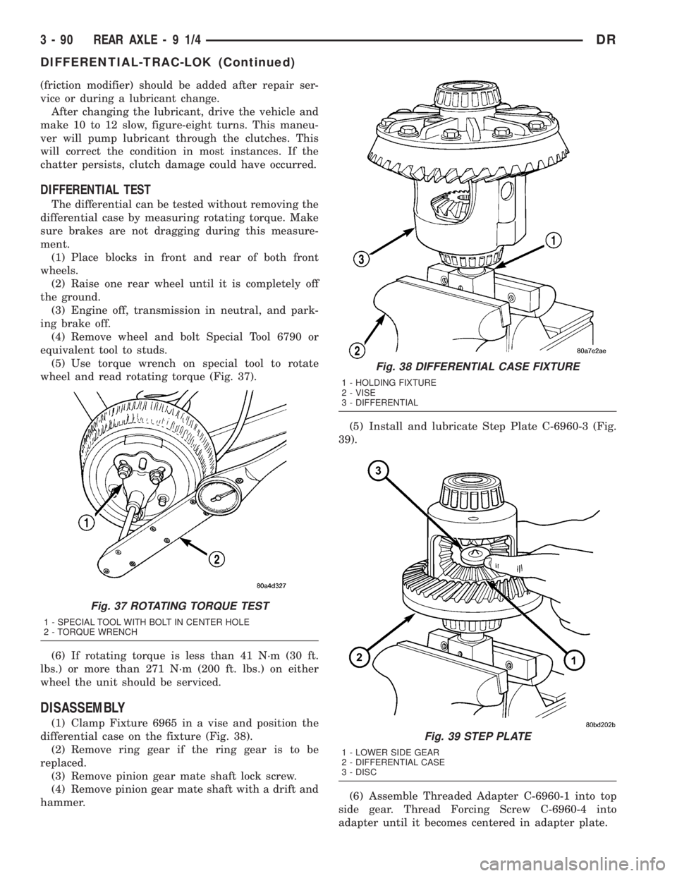
wheel and read rotating torque (Fig. 37).
(6) If rotating torque is less than 41 N´m (30 ft.
lbs.) or more than 271 N´m (200 ft. lbs.) on either
wheel the unit should be serviced.
DISASSEMBLY
(1) Clamp Fixture 6965 in a vise and position the
differential case on the fixture (Fig. 38).
(2) Remove ring gear if the ring gear is to be
replaced.
(3) Remove pinion gear mate shaft lock screw.
(4) Remove pinion gear mate shaft with a drift and
hammer.(5) Install and lubricate Step Plate C-6960-3 (Fig.
39).
(6) Assemble Threaded Adapter C-6960-1 into top
side gear. Thread Forcing Screw C-6960-4 into
adapter until it becomes centered in adapter plate.
Fig. 37 ROTATING TORQUE TEST
1 - SPECIAL TOOL WITH BOLT IN CENTER HOLE
2 - TORQUE WRENCH
Fig. 38 DIFFERENTIAL CASE FIXTURE
1 - HOLDING FIXTURE
2 - VISE
3 - DIFFERENTIAL
Fig. 39 STEP PLATE
1 - LOWER SIDE GEAR
2 - DIFFERENTIAL CASE
3 - DISC
3 - 90 REAR AXLE-91/4DR
DIFFERENTIAL-TRAC-LOK (Continued)
Page 173 of 2895
REAR AXLE - 10 1/2 AA
TABLE OF CONTENTS
page page
REAR AXLE - 10 1/2 AA
DESCRIPTION........................100
OPERATION..........................100
DIAGNOSIS AND TESTING...............100
REMOVAL............................103
INSTALLATION........................103
ADJUSTMENTS.......................104
SPECIFICATIONS......................108
SPECIAL TOOLS.......................108
AXLE SHAFTS
REMOVAL............................111
INSTALLATION........................111
AXLE BEARINGS
REMOVAL............................112
INSTALLATION........................112
PINION SEAL
REMOVAL............................113
INSTALLATION........................113
DIFFERENTIAL
DESCRIPTION........................114OPERATION..........................114
REMOVAL............................115
DISASSEMBLY........................115
ASSEMBLY...........................116
INSTALLATION........................117
DIFFERENTIAL TRAC-RITE
DESCRIPTION........................118
OPERATION..........................118
DISASSEMBLY........................118
CLEANING...........................119
INSPECTION..........................119
ASSEMBLY...........................120
DIFFERENTIAL CASE BEARINGS
REMOVAL............................121
INSTALLATION........................121
PINION GEAR/RING GEAR/TONE RING
REMOVAL............................122
INSTALLATION........................123
REAR AXLE - 10 1/2 AA
DESCRIPTION
The axle consists of a cast iron center casting dif-
ferential housing with axle shaft tubes extending
from each side. The tubes are pressed into the differ-
ential housing and welded. The design has the cen-
terline of the pinion set below the centerline of the
ring gear. The axle is a full floating axle where the
loads are supported by the axle housing tubes. The
axle has a vent used to relieve internal pressure
caused by lubricant vaporization and internal expan-
sion.
OPERATION
The axle receives power from the propeller shaft.
The propeller shaft is connected to the pinion gear
which rotates the differential through the gear mesh
with the ring gear bolted to the differential case. The
engine power is transmitted to the axle shafts
through the pinion mate and side gears. The side
gears are splined to the axle shafts.
DIAGNOSIS AND TESTING
GEAR NOISE
Axle gear noise can be caused by insufficient lubri-
cant, incorrect backlash, incorrect pinion depth, tooth
contact, worn/damaged gears, or the carrier housing
not having the proper offset and squareness.
Gear noise usually happens at a specific speed
range. The noise can also occur during a specific type
of driving condition. These conditions are accelera-
tion, deceleration, coast, or constant load.
When road testing, first warm-up the axle fluid by
driving the vehicle at least 5 miles and then acceler-
ate the vehicle to the speed range where the noise is
the greatest. Shift out-of-gear and coast through the
peak-noise range. If the noise stops or changes
greatly:
²Check for insufficient lubricant.
²Incorrect ring gear backlash.
²Gear damage.
Differential side gears and pinions can be checked
by turning the vehicle. They usually do not cause
noise during straight-ahead driving when the gears
are unloaded. The side gears are loaded during vehi-
cle turns. A worn pinion shaft can also cause a snap-
ping or a knocking noise.
3 - 100 REAR AXLE - 10 1/2 AADR
Page 174 of 2895
BEARING NOISE
The axle shaft, differential and pinion bearings can
all produce noise when worn or damaged. Bearing
noise can be either a whining, or a growling sound.
Pinion bearings have a constant-pitch noise. This
noise changes only with vehicle speed. Pinion bearing
noise will be higher pitched because it rotates at a
faster rate. Drive the vehicle and load the differen-
tial. If bearing noise occurs, the rear pinion bearing
is the source of the noise. If the bearing noise is
heard during a coast, the front pinion bearing is the
source.
Worn or damaged differential bearings usually pro-
duce a low pitch noise. Differential bearing noise is
similar to pinion bearing noise. The pitch of differen-
tial bearing noise is also constant and varies only
with vehicle speed.
Axle shaft bearings produce noise and vibration
when worn or damaged. The noise generally changes
when the bearings are loaded. Road test the vehicle.
Turn the vehicle sharply to the left and to the right.
This will load the bearings and change the noise
level. Where axle bearing damage is slight, the noise
is usually not noticeable at speeds above 30 mph.
LOW SPEED KNOCK
Low speed knock is generally caused by a worn
U-joint or by worn side-gear thrust washers. A worn
pinion shaft bore will also cause low speed knock.
VIBRATION
Vibration at the rear of the vehicle is usually
caused by a:
²Damaged drive shaft.
²Missing drive shaft balance weight(s).²Worn or out-of-balance wheels.
²Loose wheel lug nuts.
²Worn U-joint(s).
²Loose/broken springs.
²Damaged axle shaft bearing(s).
²Loose pinion gear nut.
²Excessive pinion yoke run out.
²Bent axle shaft(s).
Check for loose or damaged front-end components
or engine/transmission mounts. These components
can contribute to what appears to be a rearend vibra-
tion. Do not overlook engine accessories, brackets
and drive belts.
NOTE: All driveline components should be exam-
ined before starting any repair.
DRIVELINE SNAP
A snap or clunk noise when the vehicle is shifted
into gear (or the clutch engaged), can be caused by:
²High engine idle speed.
²Transmission shift operation.
²Loose engine/transmission/transfer case mounts.
²Worn U-joints.
²Loose spring mounts.
²Loose pinion gear nut and yoke.
²Excessive ring gear backlash.
²Excessive side gear to case clearance.
The source of a snap or a clunk noise can be deter-
mined with the assistance of a helper. Raise the vehi-
cle on a hoist with the wheels free to rotate. Instruct
the helper to shift the transmission into gear. Listen
for the noise, a mechanics stethoscope is helpful in
isolating the source of a noise.
DIAGNOSTIC CHART
Condition Possible Causes Correction
Wheel Noise 1. Wheel loose. 1. Tighten loose nuts.
2. Faulty, brinelled wheel bearing. 2. Replace bearing.
Axle Shaft Noise 1. Misaligned axle tube. 1. Inspect axle tube alignment.
Correct as necessary.
2. Bent or sprung axle shaft. 2. Inspect and correct as necessary.
DRREAR AXLE - 10 1/2 AA 3 - 101
REAR AXLE - 10 1/2 AA (Continued)
Page 190 of 2895
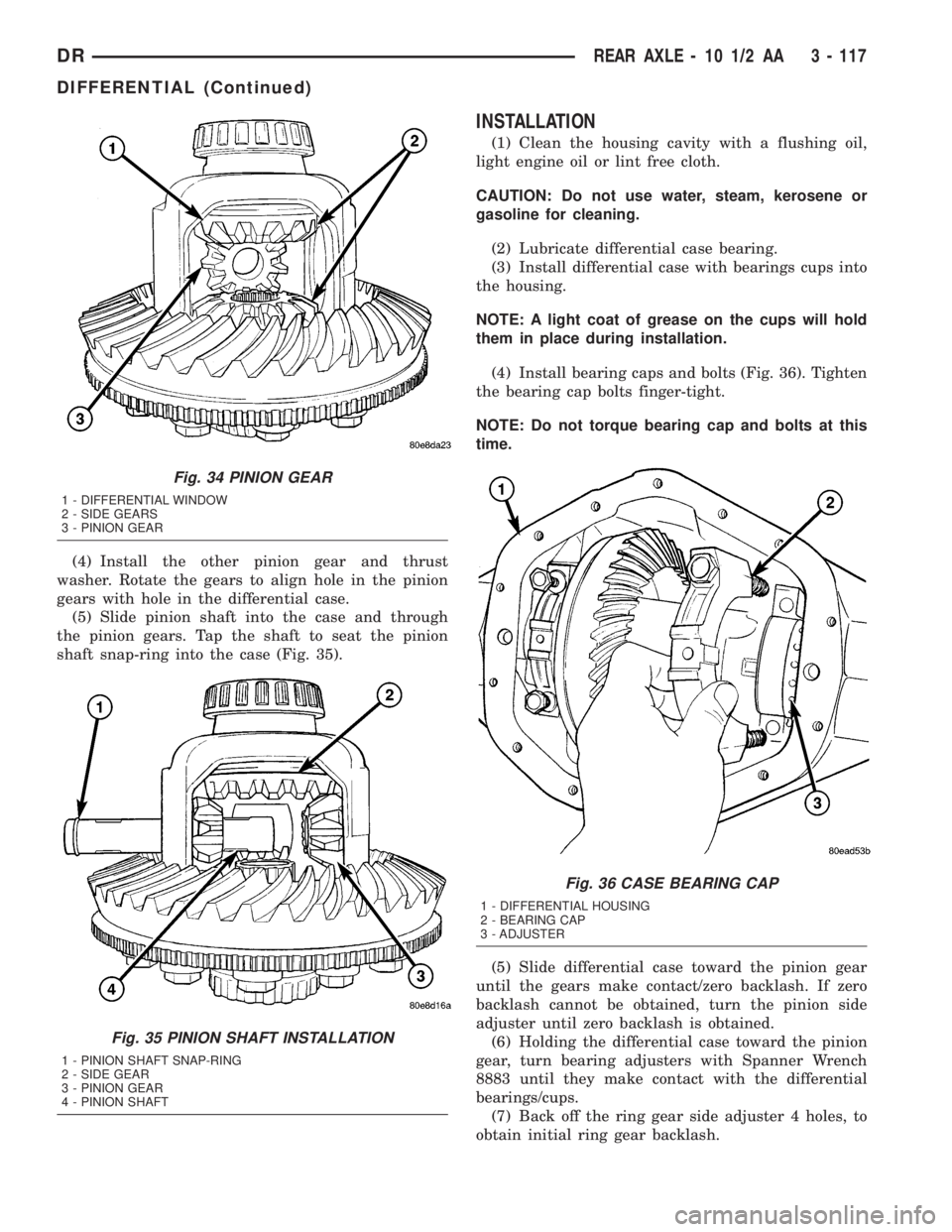
(4) Install the other pinion gear and thrust
washer. Rotate the gears to align hole in the pinion
gears with hole in the differential case.
(5) Slide pinion shaft into the case and through
the pinion gears. Tap the shaft to seat the pinion
shaft snap-ring into the case (Fig. 35).
INSTALLATION
(1) Clean the housing cavity with a flushing oil,
light engine oil or lint free cloth.
CAUTION: Do not use water, steam, kerosene or
gasoline for cleaning.
(2) Lubricate differential case bearing.
(3) Install differential case with bearings cups into
the housing.
NOTE: A light coat of grease on the cups will hold
them in place during installation.
(4) Install bearing caps and bolts (Fig. 36). Tighten
the bearing cap bolts finger-tight.
NOTE: Do not torque bearing cap and bolts at this
time.
(5) Slide differential case toward the pinion gear
until the gears make contact/zero backlash. If zero
backlash cannot be obtained, turn the pinion side
adjuster until zero backlash is obtained.
(6) Holding the differential case toward the pinion
gear, turn bearing adjusters with Spanner Wrench
8883 until they make contact with the differential
bearings/cups.
(7) Back off the ring gear side adjuster 4 holes, to
obtain initial ring gear backlash.
Fig. 34 PINION GEAR
1 - DIFFERENTIAL WINDOW
2 - SIDE GEARS
3 - PINION GEAR
Fig. 35 PINION SHAFT INSTALLATION
1 - PINION SHAFT SNAP-RING
2 - SIDE GEAR
3 - PINION GEAR
4 - PINION SHAFT
Fig. 36 CASE BEARING CAP
1 - DIFFERENTIAL HOUSING
2 - BEARING CAP
3 - ADJUSTER
DRREAR AXLE - 10 1/2 AA 3 - 117
DIFFERENTIAL (Continued)
Page 200 of 2895
REAR AXLE - 11 1/2 AA
TABLE OF CONTENTS
page page
REAR AXLE - 11 1/2 AA
DESCRIPTION........................127
OPERATION..........................127
DIAGNOSIS AND TESTING...............127
REMOVAL............................130
INSTALLATION........................130
ADJUSTMENTS.......................131
SPECIFICATIONS......................135
SPECIAL TOOLS.......................135
AXLE SHAFTS
REMOVAL............................138
INSTALLATION........................138
AXLE BEARINGS
REMOVAL............................138
INSTALLATION........................139
PINION SEAL
REMOVAL............................140
INSTALLATION........................140
DIFFERENTIAL
DESCRIPTION........................141OPERATION..........................141
REMOVAL............................142
DISASSEMBLY........................142
ASSEMBLY...........................143
INSTALLATION........................144
DIFFERENTIAL TRAC-RITE
DESCRIPTION........................145
OPERATION..........................145
DISASSEMBLY........................145
CLEANING...........................146
INSPECTION.........................146
ASSEMBLY...........................147
DIFFERENTIAL CASE BEARINGS
REMOVAL............................148
INSTALLATION........................148
PINION GEAR/RING GEAR/TONE RING
REMOVAL............................149
INSTALLATION........................150
REAR AXLE - 11 1/2 AA
DESCRIPTION
The axle consists of a cast iron center casting dif-
ferential housing with axle shaft tubes extending
from each side. The tubes are pressed into the differ-
ential housing and welded. The design has the cen-
terline of the pinion set below the centerline of the
ring gear. The axle is a full floating axle where the
loads are supported by the axle housing tubes. The
axle has a vent used to relieve internal pressure
caused by lubricant vaporization and internal expan-
sion.
OPERATION
The axle receives power from the propeller shaft.
The propeller shaft is connected to the pinion gear
which rotates the differential through the gear mesh
with the ring gear bolted to the differential case. The
engine power is transmitted to the axle shafts
through the pinion mate and side gears. The side
gears are splined to the axle shafts.
DIAGNOSIS AND TESTING
GEAR NOISE
Axle gear noise can be caused by insufficient lubri-
cant, incorrect backlash, incorrect pinion depth, tooth
contact, worn/damaged gears, or the carrier housing
not having the proper offset and squareness.
Gear noise usually happens at a specific speed
range. The noise can also occur during a specific type
of driving condition. These conditions are accelera-
tion, deceleration, coast, or constant load.
When road testing, first warm-up the axle fluid by
driving the vehicle at least 5 miles and then acceler-
ate the vehicle to the speed range where the noise is
the greatest. Shift out-of-gear and coast through the
peak-noise range. If the noise stops or changes
greatly:
²Check for insufficient lubricant.
²Incorrect ring gear backlash.
²Gear damage.
Differential side gears and pinions can be checked
by turning the vehicle. They usually do not cause
noise during straight-ahead driving when the gears
are unloaded. The side gears are loaded during vehi-
cle turns. A worn pinion shaft can also cause a snap-
ping or a knocking noise.
DRREAR AXLE - 11 1/2 AA 3 - 127
Page 201 of 2895
BEARING NOISE
The axle shaft, differential and pinion bearings can
all produce noise when worn or damaged. Bearing
noise can be either a whining, or a growling sound.
Pinion bearings have a constant-pitch noise. This
noise changes only with vehicle speed. Pinion bearing
noise will be higher pitched because it rotates at a
faster rate. Drive the vehicle and load the differen-
tial. If bearing noise occurs, the rear pinion bearing
is the source of the noise. If the bearing noise is
heard during a coast, the front pinion bearing is the
source.
Worn or damaged differential bearings usually pro-
duce a low pitch noise. Differential bearing noise is
similar to pinion bearing noise. The pitch of differen-
tial bearing noise is also constant and varies only
with vehicle speed.
Axle shaft bearings produce noise and vibration
when worn or damaged. The noise generally changes
when the bearings are loaded. Road test the vehicle.
Turn the vehicle sharply to the left and to the right.
This will load the bearings and change the noise
level. Where axle bearing damage is slight, the noise
is usually not noticeable at speeds above 30 mph.
LOW SPEED KNOCK
Low speed knock is generally caused by a worn
U-joint or by worn side±gear thrust washers. A worn
pinion shaft bore will also cause low speed knock.
VIBRATION
Vibration at the rear of the vehicle is usually
caused by a:
²Damaged drive shaft.
²Missing drive shaft balance weight(s).²Worn or out-of-balance wheels.
²Loose wheel lug nuts.
²Worn U-joint(s).
²Loose/broken springs.
²Damaged axle shaft bearing(s).
²Loose pinion gear nut.
²Excessive pinion yoke run out.
²Bent axle shaft(s).
Check for loose or damaged front-end components
or engine/transmission mounts. These components
can contribute to what appears to be a rearend vibra-
tion. Do not overlook engine accessories, brackets
and drive belts.
NOTE: All driveline components should be exam-
ined before starting any repair.
DRIVELINE SNAP
A snap or clunk noise when the vehicle is shifted
into gear (or the clutch engaged), can be caused by:
²High engine idle speed.
²Transmission shift operation.
²Loose engine/transmission/transfer case mounts.
²Worn U-joints.
²Loose spring mounts.
²Loose pinion gear nut and yoke.
²Excessive ring gear backlash.
²Excessive side gear to case clearance.
The source of a snap or a clunk noise can be deter-
mined with the assistance of a helper. Raise the vehi-
cle on a hoist with the wheels free to rotate. Instruct
the helper to shift the transmission into gear. Listen
for the noise, a mechanics stethoscope is helpful in
isolating the source of a noise.
DIAGNOSTIC CHART
Condition Possible Causes Correction
Wheel Noise 1. Wheel loose. 1. Tighten loose nuts.
2. Faulty, brinelled wheel bearing. 2. Replace bearing.
Axle Shaft Noise 1. Misaligned axle tube. 1. Inspect axle tube alignment.
Correct as necessary.
2. Bent or sprung axle shaft. 2. Inspect and correct as necessary.
3 - 128 REAR AXLE - 11 1/2 AADR
REAR AXLE - 11 1/2 AA (Continued)