sensor DODGE RAM 2003 Service Owner's Guide
[x] Cancel search | Manufacturer: DODGE, Model Year: 2003, Model line: RAM, Model: DODGE RAM 2003Pages: 2895, PDF Size: 83.15 MB
Page 301 of 2895
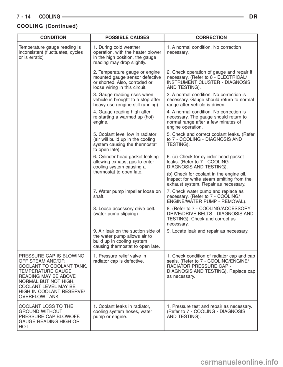
CONDITION POSSIBLE CAUSES CORRECTION
Temperature gauge reading is
inconsistent (flucttuates, cycles
or is erratic)1. During cold weather
operation, with the heater blower
in the high position, the gauge
reading may drop slightly.1. A normal condition. No correction
necessary.
2. Temperature gauge or engine
mounted gauge sensor defective
or shorted. Also, corroded or
loose wiring in this circuit.2. Check operation of gauge and repair if
necessary. (Refer to 8 - ELECTRICAL/
INSTRUMENT CLUSTER - DIAGNOSIS
AND TESTING).
3. Gauge reading rises when
vehicle is brought to a stop after
heavy use (engine still running)3. A normal condition. No correction is
necessary. Gauge should return to normal
range after vehicle is driven.
4. Gauge reading high after
re-starting a warmed up (hot)
engine.4. A normal condition. No correction is
necessary. The gauge should return to
normal range after a few minutes of
engine operation.
5. Coolant level low in radiator
(air will build up in the cooling
system causing the thermostat
to open late).5. Check and correct coolant leaks. (Refer
to 7 - COOLING - DIAGNOSIS AND
TESTING).
6. Cylinder head gasket leaking
allowing exhaust gas to enter
cooling system causing a
thermostat to open late.6. (a) Check for cylinder head gasket
leaks. (Refer to 7 - COOLING -
DIAGNOSIS AND TESTING).
(b) Check for coolant in the engine oil.
Inspect for white steam emitting from the
exhaust system. Repair as necessary.
7. Water pump impeller loose on
shaft.7. Check water pump and replace as
necessary. (Refer to 7 - COOLING/
ENGINE/WATER PUMP - REMOVAL).
8. Loose accessory drive belt.
(water pump slipping)8. (Refer to 7 - COOLING/ACCESSORY
DRIVE/DRIVE BELTS - DIAGNOSIS AND
TESTING). Check and correct as
necessary.
9. Air leak on the suction side of
the water pump allows air to
build up in cooling system
causing thermostat to open late.9. Locate leak and repair as necessary.
PRESSURE CAP IS BLOWING
OFF STEAM AND/OR
COOLANT TO COOLANT TANK.
TEMPERATURE GAUGE
READING MAY BE ABOVE
NORMAL BUT NOT HIGH.
COOLANT LEVEL MAY BE
HIGH IN COOLANT RESERVE/
OVERFLOW TANK1. Pressure relief valve in
radiator cap is defective.1. Check condition of radiator cap and cap
seals. (Refer to 7 - COOLING/ENGINE/
RADIATOR PRESSURE CAP -
DIAGNOSIS AND TESTING). Replace cap
as necessary.
COOLANT LOSS TO THE
GROUND WITHOUT
PRESSURE CAP BLOWOFF.
GAUGE READING HIGH OR
HOT1. Coolant leaks in radiator,
cooling system hoses, water
pump or engine.1. Pressure test and repair as necessary.
(Refer to 7 - COOLING - DIAGNOSIS
AND TESTING).
7 - 14 COOLINGDR
COOLING (Continued)
Page 321 of 2895
NOTE: The engine speed sensor face is very close
to the accessory drive belt. Inspect engine speed
sensor and wire harness for damage when acces-
sory drive belt has been replaced due to failure or
abnormal conditions.
REMOVAL
CAUTION: Do not attempt to check belt tension with
a belt tension gauge on vehicles equipped with an
automatic belt tensioner. Refer to Automatic Belt
Tensioner in this group.
NOTE: The belt routing schematics are published
from the latest information available at the time of
publication. If anything differs between these sche-
matics and the Belt Routing Label, use the sche-
matics on Belt Routing Label.This label is located in
the engine compartment.
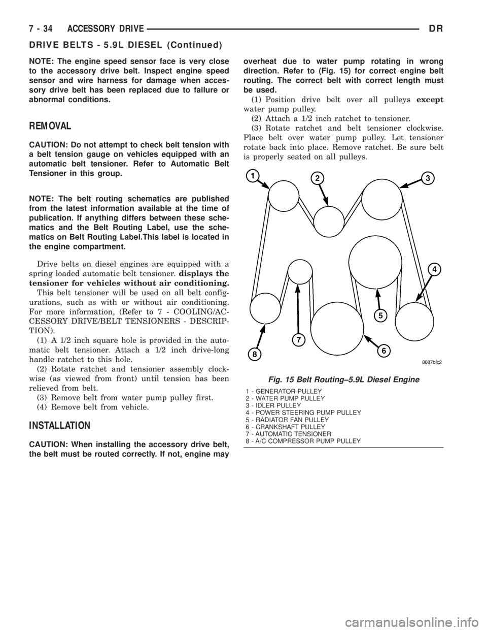
Drive belts on diesel engines are equipped with a
spring loaded automatic belt tensioner.displays the
tensioner for vehicles without air conditioning.
This belt tensioner will be used on all belt config-
urations, such as with or without air conditioning.
For more information, (Refer to 7 - COOLING/AC-
CESSORY DRIVE/BELT TENSIONERS - DESCRIP-
TION).
(1) A 1/2 inch square hole is provided in the auto-
matic belt tensioner. Attach a 1/2 inch drive-long
handle ratchet to this hole.
(2) Rotate ratchet and tensioner assembly clock-
wise (as viewed from front) until tension has been
relieved from belt.
(3) Remove belt from water pump pulley first.
(4) Remove belt from vehicle.
INSTALLATION
CAUTION: When installing the accessory drive belt,
the belt must be routed correctly. If not, engine mayoverheat due to water pump rotating in wrong
direction. Refer to (Fig. 15) for correct engine belt
routing. The correct belt with correct length must
be used.
(1) Position drive belt over all pulleysexcept
water pump pulley.
(2) Attach a 1/2 inch ratchet to tensioner.
(3) Rotate ratchet and belt tensioner clockwise.
Place belt over water pump pulley. Let tensioner
rotate back into place. Remove ratchet. Be sure belt
is properly seated on all pulleys.
Fig. 15 Belt Routing±5.9L Diesel Engine
1 - GENERATOR PULLEY
2 - WATER PUMP PULLEY
3 - IDLER PULLEY
4 - POWER STEERING PUMP PULLEY
5 - RADIATOR FAN PULLEY
6 - CRANKSHAFT PULLEY
7 - AUTOMATIC TENSIONER
8 - A/C COMPRESSOR PUMP PULLEY
7 - 34 ACCESSORY DRIVEDR
DRIVE BELTS - 5.9L DIESEL (Continued)
Page 322 of 2895
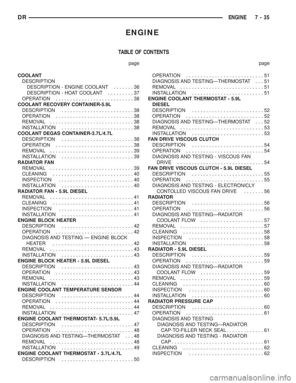
ENGINE
TABLE OF CONTENTS
page page
COOLANT
DESCRIPTION
DESCRIPTION - ENGINE COOLANT.......36
DESCRIPTION - HOAT COOLANT.........37
OPERATION...........................38
COOLANT RECOVERY CONTAINER-5.9L
DESCRIPTION.........................38
OPERATION...........................38
REMOVAL.............................38
INSTALLATION.........................38
COOLANT DEGAS CONTAINER-3.7L/4.7L
DESCRIPTION.........................38
OPERATION...........................38
REMOVAL.............................39
INSTALLATION.........................39
RADIATOR FAN
REMOVAL.............................39
CLEANING............................40
INSPECTION..........................40
INSTALLATION.........................40
RADIATOR FAN - 5.9L DIESEL
REMOVAL.............................41
CLEANING............................41
INSPECTION..........................41
INSTALLATION.........................41
ENGINE BLOCK HEATER
DESCRIPTION.........................42
OPERATION...........................42
DIAGNOSIS AND TESTING Ð ENGINE BLOCK
HEATER ............................42
REMOVAL.............................43
INSTALLATION.........................43
ENGINE BLOCK HEATER - 5.9L DIESEL
DESCRIPTION.........................43
OPERATION...........................43
REMOVAL.............................43
INSTALLATION.........................44
ENGINE COOLANT TEMPERATURE SENSOR
DESCRIPTION.........................44
OPERATION...........................44
REMOVAL.............................44
INSTALLATION.........................47
ENGINE COOLANT THERMOSTAT- 5.7L/5.9L
DESCRIPTION.........................47
OPERATION...........................48
DIAGNOSIS AND TESTINGÐTHERMOSTAT . . . 48
REMOVAL.............................48
INSTALLATION.........................49
ENGINE COOLANT THERMOSTAT - 3.7L/4.7L
DESCRIPTION.........................50OPERATION...........................51
DIAGNOSIS AND TESTINGÐTHERMOSTAT . . . 51
REMOVAL.............................51
INSTALLATION.........................51
ENGINE COOLANT THERMOSTAT - 5.9L
DIESEL
DESCRIPTION.........................52
OPERATION...........................52
DIAGNOSIS AND TESTINGÐTHERMOSTAT . . . 52
REMOVAL.............................53
INSTALLATION.........................53
FAN DRIVE VISCOUS CLUTCH
DESCRIPTION.........................54
OPERATION...........................54
DIAGNOSIS AND TESTING - VISCOUS FAN
DRIVE..............................54
FAN DRIVE VISCOUS CLUTCH - 5.9L DIESEL
DESCRIPTION.........................55
OPERATION...........................55
DIAGNOSIS AND TESTING - ELECTRONICLY
CONTOLLED VISCOUS FAN DRIVE.......56
RADIATOR
DESCRIPTION.........................56
OPERATION...........................56
DIAGNOSIS AND TESTINGÐRADIATOR
COOLANT FLOW......................57
REMOVAL.............................57
CLEANING............................58
INSPECTION..........................58
INSTALLATION.........................58
RADIATOR - 5.9L DIESEL
DESCRIPTION.........................59
OPERATION...........................59
DIAGNOSIS AND TESTINGÐRADIATOR
COOLANT FLOW......................59
REMOVAL.............................59
CLEANING............................60
INSPECTION..........................60
INSTALLATION.........................60
RADIATOR PRESSURE CAP
DESCRIPTION.........................60
OPERATION...........................61
DIAGNOSIS AND TESTING
DIAGNOSIS AND TESTINGÐRADIATOR
CAP-TO-FILLER NECK SEAL.............61
DIAGNOSIS AND TESTING - RADIATOR
CAP................................61
CLEANING............................62
INSPECTION..........................62
DRENGINE 7 - 35
Page 331 of 2895
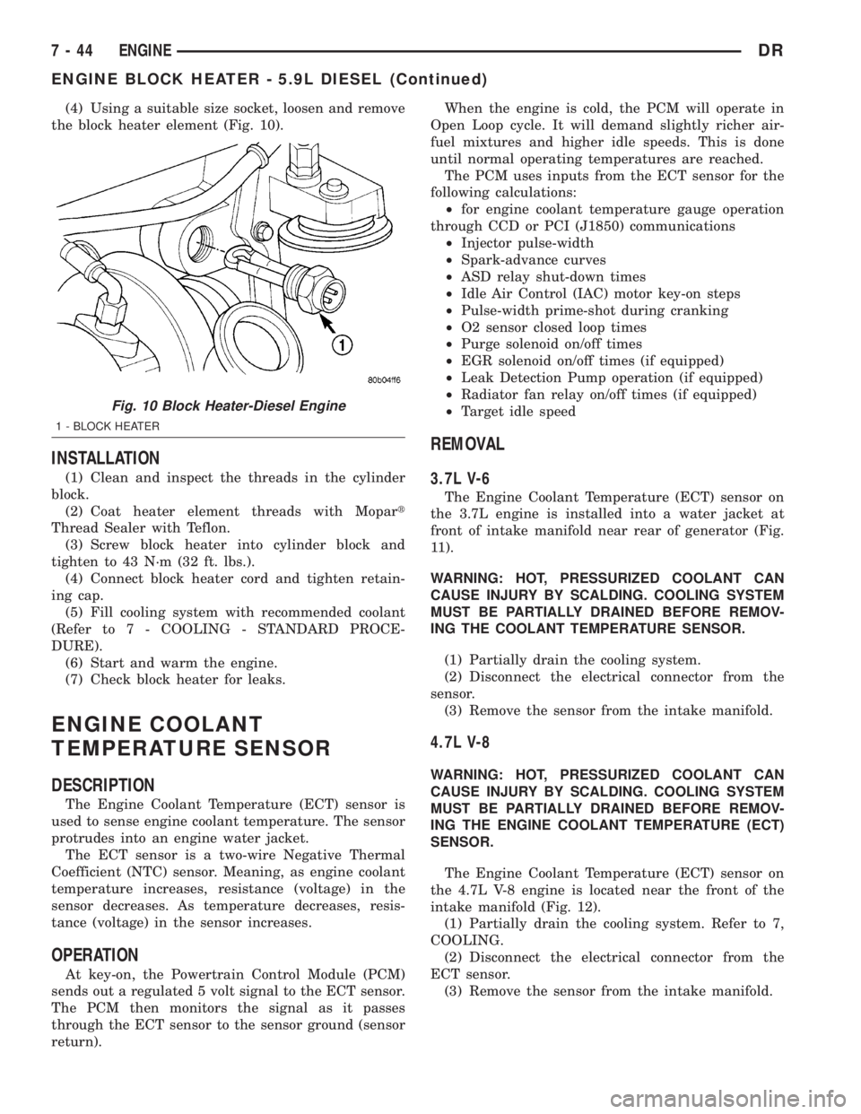
(4) Using a suitable size socket, loosen and remove
the block heater element (Fig. 10).
INSTALLATION
(1) Clean and inspect the threads in the cylinder
block.
(2) Coat heater element threads with Mopart
Thread Sealer with Teflon.
(3) Screw block heater into cylinder block and
tighten to 43 N´m (32 ft. lbs.).
(4) Connect block heater cord and tighten retain-
ing cap.
(5) Fill cooling system with recommended coolant
(Refer to 7 - COOLING - STANDARD PROCE-
DURE).
(6) Start and warm the engine.
(7) Check block heater for leaks.
ENGINE COOLANT
TEMPERATURE SENSOR
DESCRIPTION
The Engine Coolant Temperature (ECT) sensor is
used to sense engine coolant temperature. The sensor
protrudes into an engine water jacket.
The ECT sensor is a two-wire Negative Thermal
Coefficient (NTC) sensor. Meaning, as engine coolant
temperature increases, resistance (voltage) in the
sensor decreases. As temperature decreases, resis-
tance (voltage) in the sensor increases.
OPERATION
At key-on, the Powertrain Control Module (PCM)
sends out a regulated 5 volt signal to the ECT sensor.
The PCM then monitors the signal as it passes
through the ECT sensor to the sensor ground (sensor
return).When the engine is cold, the PCM will operate in
Open Loop cycle. It will demand slightly richer air-
fuel mixtures and higher idle speeds. This is done
until normal operating temperatures are reached.
The PCM uses inputs from the ECT sensor for the
following calculations:
²for engine coolant temperature gauge operation
through CCD or PCI (J1850) communications
²Injector pulse-width
²Spark-advance curves
²ASD relay shut-down times
²Idle Air Control (IAC) motor key-on steps
²Pulse-width prime-shot during cranking
²O2 sensor closed loop times
²Purge solenoid on/off times
²EGR solenoid on/off times (if equipped)
²Leak Detection Pump operation (if equipped)
²Radiator fan relay on/off times (if equipped)
²Target idle speed
REMOVAL
3.7L V-6
The Engine Coolant Temperature (ECT) sensor on
the 3.7L engine is installed into a water jacket at
front of intake manifold near rear of generator (Fig.
11).
WARNING: HOT, PRESSURIZED COOLANT CAN
CAUSE INJURY BY SCALDING. COOLING SYSTEM
MUST BE PARTIALLY DRAINED BEFORE REMOV-
ING THE COOLANT TEMPERATURE SENSOR.
(1) Partially drain the cooling system.
(2) Disconnect the electrical connector from the
sensor.
(3) Remove the sensor from the intake manifold.
4.7L V-8
WARNING: HOT, PRESSURIZED COOLANT CAN
CAUSE INJURY BY SCALDING. COOLING SYSTEM
MUST BE PARTIALLY DRAINED BEFORE REMOV-
ING THE ENGINE COOLANT TEMPERATURE (ECT)
SENSOR.
The Engine Coolant Temperature (ECT) sensor on
the 4.7L V-8 engine is located near the front of the
intake manifold (Fig. 12).
(1) Partially drain the cooling system. Refer to 7,
COOLING.
(2) Disconnect the electrical connector from the
ECT sensor.
(3) Remove the sensor from the intake manifold.
Fig. 10 Block Heater-Diesel Engine
1 - BLOCK HEATER
7 - 44 ENGINEDR
ENGINE BLOCK HEATER - 5.9L DIESEL (Continued)
Page 332 of 2895
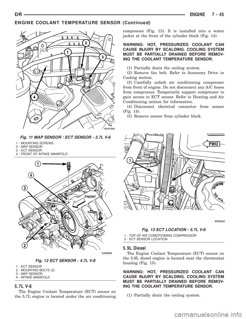
5.7L V-8
The Engine Coolant Temperature (ECT) sensor on
the 5.7L engine is located under the air conditioningcompressor (Fig. 13). It is installed into a water
jacket at the front of the cylinder block (Fig. 14).
WARNING: HOT, PRESSURIZED COOLANT CAN
CAUSE INJURY BY SCALDING. COOLING SYSTEM
MUST BE PARTIALLY DRAINED BEFORE REMOV-
ING THE COOLANT TEMPERATURE SENSOR.
(1) Partially drain the cooling system.
(2) Remove fan belt. Refer to Accessory Drive in
Cooling section.
(3) Carefully unbolt air conditioning compressor
from front of engine. Do not disconnect any A/C hoses
from compressor. Temporarily support compressor to
gain access to ECT sensor. Refer to Heating and Air
Conditioning section for information.
(4) Disconnect electrical connector from sensor
(Fig. 14).
(5) Remove sensor from cylinder block.
5.9L Diesel
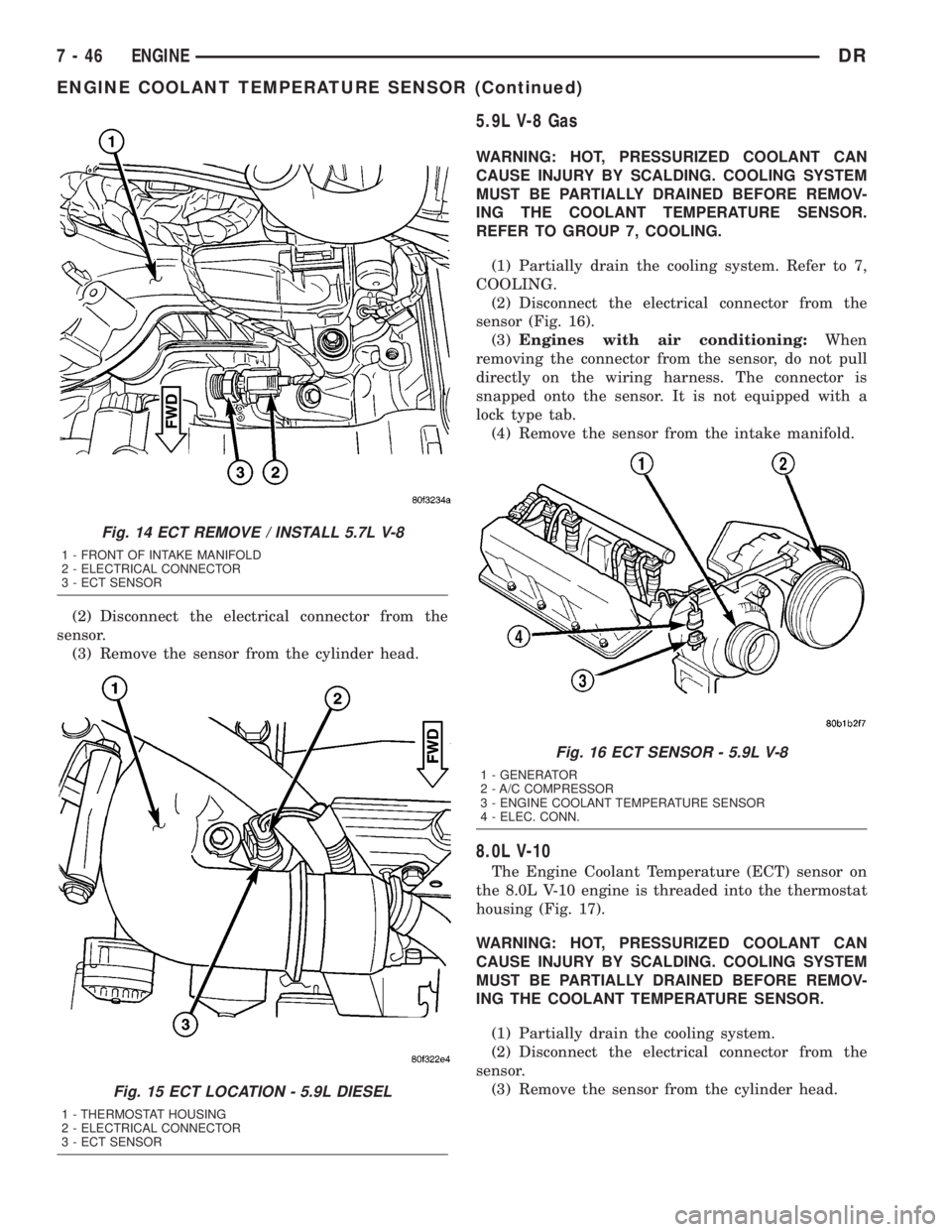
The Engine Coolant Temperature (ECT) sensor on
the 5.9L diesel engine is located near the thermostat
housing (Fig. 15).
WARNING: HOT, PRESSURIZED COOLANT CAN
CAUSE INJURY BY SCALDING. COOLING SYSTEM
MUST BE PARTIALLY DRAINED BEFORE REMOV-
ING THE COOLANT TEMPERATURE SENSOR.
(1) Partially drain the cooling system.
Fig. 11 MAP SENSOR / ECT SENSOR - 3.7L V-6
1 - MOUNTING SCREWS
2 - MAP SENSOR
3 - ECT SENSOR
4 - FRONT OF INTAKE MANIFOLD
Fig. 12 ECT SENSOR - 4.7L V-8
1 - ECT SENSOR
2 - MOUNTING BOLTS (2)
3 - MAP SENSOR
4 - INTAKE MANIFOLD
Fig. 13 ECT LOCATION - 5.7L V-8
1 - TOP OF AIR CONDITIONING COMPRESSOR
2 - ECT SENSOR LOCATION
DRENGINE 7 - 45
ENGINE COOLANT TEMPERATURE SENSOR (Continued)
Page 333 of 2895
(2) Disconnect the electrical connector from the
sensor.
(3) Remove the sensor from the cylinder head.
5.9L V-8 Gas
WARNING: HOT, PRESSURIZED COOLANT CAN
CAUSE INJURY BY SCALDING. COOLING SYSTEM
MUST BE PARTIALLY DRAINED BEFORE REMOV-
ING THE COOLANT TEMPERATURE SENSOR.
REFER TO GROUP 7, COOLING.
(1) Partially drain the cooling system. Refer to 7,
COOLING.
(2) Disconnect the electrical connector from the
sensor (Fig. 16).
(3)Engines with air conditioning:When
removing the connector from the sensor, do not pull
directly on the wiring harness. The connector is
snapped onto the sensor. It is not equipped with a
lock type tab.
(4) Remove the sensor from the intake manifold.
8.0L V-10
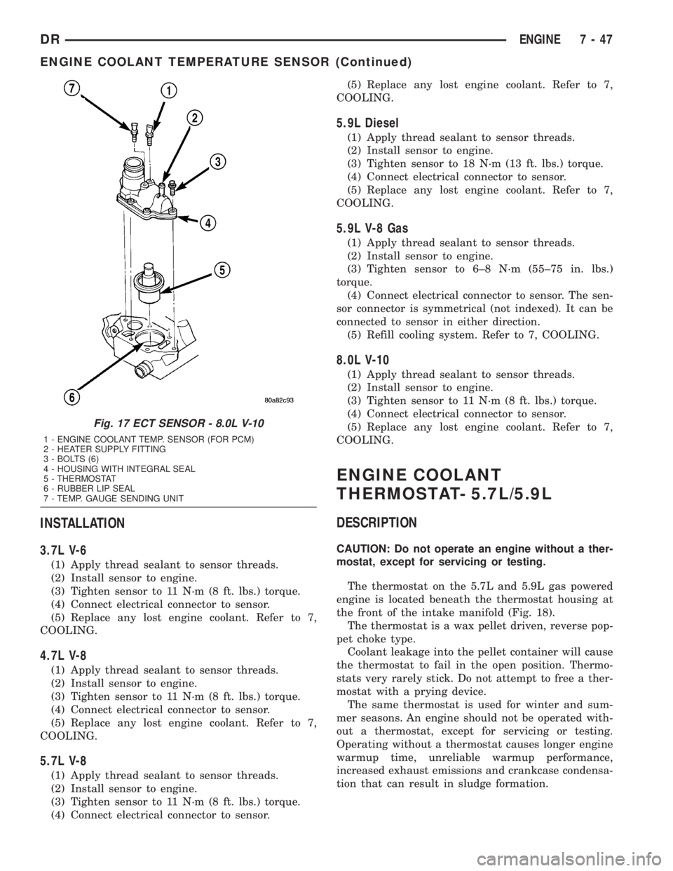
The Engine Coolant Temperature (ECT) sensor on
the 8.0L V-10 engine is threaded into the thermostat
housing (Fig. 17).
WARNING: HOT, PRESSURIZED COOLANT CAN
CAUSE INJURY BY SCALDING. COOLING SYSTEM
MUST BE PARTIALLY DRAINED BEFORE REMOV-
ING THE COOLANT TEMPERATURE SENSOR.
(1) Partially drain the cooling system.
(2) Disconnect the electrical connector from the
sensor.
(3) Remove the sensor from the cylinder head.
Fig. 14 ECT REMOVE / INSTALL 5.7L V-8
1 - FRONT OF INTAKE MANIFOLD
2 - ELECTRICAL CONNECTOR
3 - ECT SENSOR
Fig. 15 ECT LOCATION - 5.9L DIESEL
1 - THERMOSTAT HOUSING
2 - ELECTRICAL CONNECTOR
3 - ECT SENSOR
Fig. 16 ECT SENSOR - 5.9L V-8
1 - GENERATOR
2 - A/C COMPRESSOR
3 - ENGINE COOLANT TEMPERATURE SENSOR
4 - ELEC. CONN.
7 - 46 ENGINEDR
ENGINE COOLANT TEMPERATURE SENSOR (Continued)
Page 334 of 2895
INSTALLATION
3.7L V-6
(1) Apply thread sealant to sensor threads.
(2) Install sensor to engine.
(3) Tighten sensor to 11 N´m (8 ft. lbs.) torque.
(4) Connect electrical connector to sensor.
(5) Replace any lost engine coolant. Refer to 7,
COOLING.
4.7L V-8
(1) Apply thread sealant to sensor threads.
(2) Install sensor to engine.
(3) Tighten sensor to 11 N´m (8 ft. lbs.) torque.
(4) Connect electrical connector to sensor.
(5) Replace any lost engine coolant. Refer to 7,
COOLING.
5.7L V-8
(1) Apply thread sealant to sensor threads.
(2) Install sensor to engine.
(3) Tighten sensor to 11 N´m (8 ft. lbs.) torque.
(4) Connect electrical connector to sensor.(5) Replace any lost engine coolant. Refer to 7,
COOLING.
5.9L Diesel
(1) Apply thread sealant to sensor threads.
(2) Install sensor to engine.
(3) Tighten sensor to 18 N´m (13 ft. lbs.) torque.
(4) Connect electrical connector to sensor.
(5) Replace any lost engine coolant. Refer to 7,
COOLING.
5.9L V-8 Gas
(1) Apply thread sealant to sensor threads.
(2) Install sensor to engine.
(3) Tighten sensor to 6±8 N´m (55±75 in. lbs.)
torque.
(4) Connect electrical connector to sensor. The sen-
sor connector is symmetrical (not indexed). It can be
connected to sensor in either direction.
(5) Refill cooling system. Refer to 7, COOLING.
8.0L V-10
(1) Apply thread sealant to sensor threads.
(2) Install sensor to engine.
(3) Tighten sensor to 11 N´m (8 ft. lbs.) torque.
(4) Connect electrical connector to sensor.
(5) Replace any lost engine coolant. Refer to 7,
COOLING.
ENGINE COOLANT
THERMOSTAT- 5.7L/5.9L
DESCRIPTION
CAUTION: Do not operate an engine without a ther-
mostat, except for servicing or testing.
The thermostat on the 5.7L and 5.9L gas powered
engine is located beneath the thermostat housing at
the front of the intake manifold (Fig. 18).
The thermostat is a wax pellet driven, reverse pop-
pet choke type.
Coolant leakage into the pellet container will cause
the thermostat to fail in the open position. Thermo-
stats very rarely stick. Do not attempt to free a ther-
mostat with a prying device.
The same thermostat is used for winter and sum-
mer seasons. An engine should not be operated with-
out a thermostat, except for servicing or testing.
Operating without a thermostat causes longer engine
warmup time, unreliable warmup performance,
increased exhaust emissions and crankcase condensa-
tion that can result in sludge formation.
Fig. 17 ECT SENSOR - 8.0L V-10
1 - ENGINE COOLANT TEMP. SENSOR (FOR PCM)
2 - HEATER SUPPLY FITTING
3 - BOLTS (6)
4 - HOUSING WITH INTEGRAL SEAL
5 - THERMOSTAT
6 - RUBBER LIP SEAL
7 - TEMP. GAUGE SENDING UNIT
DRENGINE 7 - 47
ENGINE COOLANT TEMPERATURE SENSOR (Continued)
Page 364 of 2895
AUDIO
TABLE OF CONTENTS
page page
AUDIO
DESCRIPTION..........................1
OPERATION............................1
DIAGNOSIS AND TESTING - AUDIO..........2
AMPLIFIER
DESCRIPTION..........................3
OPERATION............................3
REMOVAL.............................3
INSTALLATION..........................4
ANTENNA BODY & CABLE
DESCRIPTION..........................4
OPERATION............................4
DIAGNOSIS AND TESTING - ANTENNA BODY
AND CABLE..........................4
REMOVAL.............................6
INSTALLATION..........................6
INSTRUMENT PANEL ANTENNA CABLE
REMOVAL.............................6
INSTALLATION..........................7
RADIO
DESCRIPTION..........................7OPERATION............................7
REMOVAL.............................7
INSTALLATION..........................8
RADIO NOISE SUPPRESSION GROUND STRAP
DESCRIPTION..........................8
OPERATION............................8
REMOVAL.............................9
INSTALLATION.........................10
REMOTE SWITCHES
DESCRIPTION.........................10
OPERATION...........................10
DIAGNOSIS AND TESTING - REMOTE
SWITCHES..........................11
REMOVAL.............................12
INSTALLATION.........................12
SPEAKER
DESCRIPTION.........................12
OPERATION...........................12
DIAGNOSIS AND TESTING - SPEAKER......13
REMOVAL.............................13
INSTALLATION.........................15
AUDIO
DESCRIPTION
An audio system is standard factory-installed
equipment on this model. Several combinations of
radio receivers and speaker systems are offered. The
audio system uses an ignition switched source of bat-
tery current so that the system will only operate
when the ignition switch is in the RUN or ACCES-
SORY positions.
The audio system includes the following compo-
nents:
²Antenna
²Power amplifier (with premium speaker system
only)
²Radio noise suppression components
²Radio receiver
²Remote radio switches (if equipped)
²Speakers
Certain functions and features of the audio system
rely upon resources shared with other electronic
modules in the vehicle over the Programmable Com-
munication Interface (PCI) bus network. The data
bus network allows the sharing of sensor informa-
tion. For diagnosis of these electronic modules or of
the data bus network, the use of a DRB IIItscan tooland the proper Diagnostic Procedures manual are
recommended.
Refer to the appropriate wiring information for
complete standard and premium audio system circuit
diagrams. The wiring information includes proper
wire and connector repair procedures, further details
on wire harness routing and retention, as well as
pin-out and location views for the various wire har-
ness connectors, splices, and grounds.
OPERATION
The audio system components are designed to pro-
vide audio entertainment and information through
the reception, tuning and amplification of locally
broadcast radio signals in both the Amplitude Modu-
lating (AM) and Frequency Modulating (FM) com-
mercial frequency ranges.
The audio system components operate on battery
current received through a fuse in the Integrated
Power Module (IPM) on a fused ignition switch out-
put (run-acc) circuit so that the system will only
operate when the ignition switch is in the Run or
Accessory positions.
On vehicles that are equipped with the optional
remote radio switches, the Instrument Cluster
receives hard wired resistor multiplexed inputs from
the remote radio switches. The programming in the
DRAUDIO 8A - 1
Page 382 of 2895
ELECTRONIC CONTROL MODULES
TABLE OF CONTENTS
page page
COMMUNICATION
DESCRIPTION..........................1
OPERATION............................2
CONTROLLER ANTILOCK BRAKE
DESCRIPTION..........................3
OPERATION............................3
REMOVAL.............................3
INSTALLATION..........................3
DATA LINK CONNECTOR
DESCRIPTION - DATA LINK CONNECTOR.....3
OPERATION - DATA LINK CONNECTOR......3
ENGINE CONTROL MODULE
DESCRIPTION - ECM.....................4
OPERATION - ECM......................4
REMOVAL.............................4
INSTALLATION..........................5
FRONT CONTROL MODULE
DESCRIPTION..........................5
OPERATION............................5
DIAGNOSIS AND TESTING - FRONT
CONTROL MODULE....................6
REMOVAL.............................6
INSTALLATION..........................6
HEATED SEAT MODULE
DESCRIPTION..........................6
OPERATION............................6
DIAGNOSIS AND TESTING - HEATED SEAT
MODULE.............................7
REMOVAL.............................7
INSTALLATION..........................7
POWERTRAIN CONTROL MODULE
DESCRIPTION
DESCRIPTION - PCM...................8DESCRIPTION - MODES OF OPERATION....8
DESCRIPTION - 5 VOLT SUPPLIES.......10
DESCRIPTION - IGNITION CIRCUIT SENSE . 10
DESCRIPTION - POWER GROUNDS......10
DESCRIPTION - SENSOR RETURN.......10
OPERATION
OPERATION - PCM....................11
OPERATION - 5 VOLT SUPPLIES.........11
OPERATION - IGNITION CIRCUIT SENSE . . . 12
REMOVAL.............................12
INSTALLATION.........................12
SENTRY KEY IMMOBILIZER MODULE
DESCRIPTION.........................13
OPERATION...........................13
STANDARD PROCEDURE - PCM/SKIM
PROGRAMMING......................14
REMOVAL.............................15
INSTALLATION.........................15
TRANSFER CASE CONTROL MODULE
DESCRIPTION.........................15
OPERATION...........................15
TRANSMISSION CONTROL MODULE
DESCRIPTION.........................19
OPERATION...........................19
STANDARD PROCEDURE
STANDARD PROCEDURE - TCM QUICK
LEARN..............................21
STANDARD PROCEDURE - DRIVE LEARN . . 21
COMMUNICATION
DESCRIPTION
The DaimlerChrysler Programmable Communica-
tion Interface (PCI) data bus system is a single wire
multiplex system used for vehicle communications on
many DaimlerChrysler Corporation vehicles. Multi-plexing is a system that enables the transmission of
several messages over a single channel or circuit. All
DaimlerChrysler vehicles use this principle for com-
munication between various microprocessor-based
electronic control modules. The PCI data bus exceeds
the Society of Automotive Engineers (SAE) J1850
Standard for Class B Multiplexing.
DRELECTRONIC CONTROL MODULES 8E - 1
Page 383 of 2895
Many of the electronic control modules in a vehicle
require information from the same sensing device. In
the past, if information from one sensing device was
required by several controllers, a wire from each con-
troller needed to be connected in parallel to that sen-
sor. In addition, each controller utilizing analog
sensors required an Analog/Digital (A/D) converter in
order to9read9these sensor inputs. Multiplexing
reduces wire harness complexity, sensor current
loads and controller hardware because each sensing
device is connected to only one controller, which
reads and distributes the sensor information to the
other controllers over the data bus. Also, because
each controller on the data bus can access the con-
troller sensor inputs to every other controller on the
data bus, more function and feature capabilities are
possible.
In addition to reducing wire harness complexity,
component sensor current loads and controller hard-
ware, multiplexing offers a diagnostic advantage. A
multiplex system allows the information flowing
between controllers to be monitored using a diagnos-
tic scan tool. The DaimlerChrysler system allows an
electronic control module to broadcast message data
out onto the bus where all other electronic control
modules can9hear9the messages that are being sent.
When a module hears a message on the data bus
that it requires, it relays that message to its micro-
processor. Each module ignores the messages on the
data bus that are being sent to other electronic con-
trol modules.
OPERATION
Data exchange between modules is achieved by
serial transmission of encoded data over a single wire
broadcast network. The wire colors used for the PCI
data bus circuits are yellow with a violet tracer, or
violet with a yellow tracer, depending upon the appli-
cation. The PCI data bus messages are carried over
the bus in the form of Variable Pulse Width Modu-
lated (VPWM) signals. The PCI data bus speed is an
average 10.4 Kilo-bits per second (Kbps). By compar-
ison, the prior two-wire Chrysler Collision Detection
(CCD) data bus system is designed to run at 7.8125
Kbps.
The voltage network used to transmit messages
requires biasing and termination. Each module on
the PCI data bus system provides its own biasing
and termination. Each module (also referred to as a
node) terminates the bus through a terminating
resistor and a terminating capacitor. There are two
types of nodes on the bus. The dominant node termi-
nates the bus througha1KWresistor and a 3300 pF
capacitor. The Powertrain Control Module (PCM) is
the only dominant node for the PCI data bus system.A standard node terminates the bus through an 11
KW resistor and a 330 pF capacitor.
The modules bias the bus when transmitting a
message. The PCI bus uses low and high voltage lev-
els to generate signals. Low voltage is around zero
volts and the high voltage is about seven and one-
half volts. The low and high voltage levels are gener-
ated by means of variable-pulse width modulation to
form signals of varying length. The Variable Pulse
Width Modulation (VPWM) used in PCI bus messag-
ing is a method in which both the state of the bus
and the width of the pulse are used to encode bit
information. A9zero9bit is defined as a short low
pulse or a long high pulse. A9one9bit is defined as a
long low pulse or a short high pulse. A low (passive)
state on the bus does not necessarily mean a zero bit.
It also depends upon pulse width. If the width is
short, it stands for a zero bit. If the width is long, it
stands for a one bit. Similarly, a high (active) state
does not necessarily mean a one bit. This too depends
upon pulse width. If the width is short, it stands for
a one bit. If the width is long, it stands for a zero bit.
In the case where there are successive zero or one
data bits, both the state of the bus and the width of
the pulse are changed alternately. This encoding
scheme is used for two reasons. First, this ensures
that only one symbol per transition and one transi-
tion per symbol exists. On each transition, every
transmitting module must decode the symbol on the
bus and begin timing of the next symbol. Since tim-
ing of the next symbol begins with the last transition
detected on the bus, all of the modules are re-syn-
chronized with each symbol. This ensures that there
are no accumulated timing errors during PCI data
bus communication.
The second reason for this encoding scheme is to
guarantee that the zero bit is the dominant bit on
the bus. When two modules are transmitting simul-
taneously on the bus, there must be some form of
arbitration to determine which module will gain con-
trol. A data collision occurs when two modules are
transmitting different messages at the same time.
When a module is transmitting on the bus, it is read-
ing the bus at the same time to ensure message
integrity. When a collision is detected, the module
that transmitted the one bit stops sending messages
over the bus until the bus becomes idle.
Each module is capable of transmitting and receiv-
ing data simultaneously. The typical PCI bus mes-
sage has the following four components:
²Message Header- One to three bytes in length.
The header contains information identifying the mes-
sage type and length, message priority, target mod-
ule(s) and sending module.
²Data Byte(s)- This is the actual message that
is being sent.
8E - 2 ELECTRONIC CONTROL MODULESDR
COMMUNICATION (Continued)