sensor DODGE RAM 2003 Service User Guide
[x] Cancel search | Manufacturer: DODGE, Model Year: 2003, Model line: RAM, Model: DODGE RAM 2003Pages: 2895, PDF Size: 83.15 MB
Page 129 of 2895
AXLE SHAFTS
REMOVAL
(1) Remove wheel and tire assembly.
(2) Remove brake caliper, rotor and ABS wheel
speed sensor if equipped.
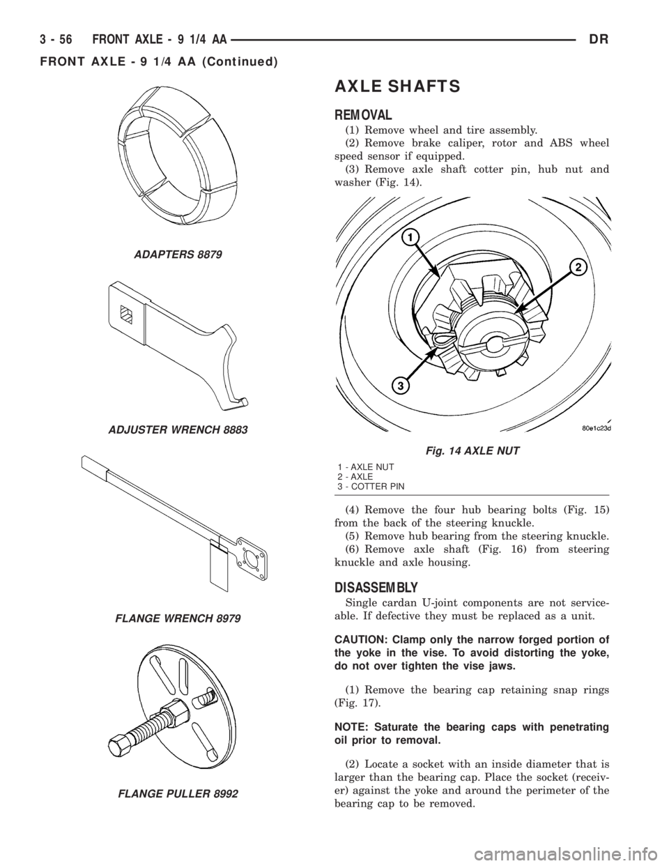
(3) Remove axle shaft cotter pin, hub nut and
washer (Fig. 14).
(4) Remove the four hub bearing bolts (Fig. 15)
from the back of the steering knuckle.
(5) Remove hub bearing from the steering knuckle.
(6) Remove axle shaft (Fig. 16) from steering
knuckle and axle housing.
DISASSEMBLY
Single cardan U-joint components are not service-
able. If defective they must be replaced as a unit.
CAUTION: Clamp only the narrow forged portion of
the yoke in the vise. To avoid distorting the yoke,
do not over tighten the vise jaws.
(1) Remove the bearing cap retaining snap rings
(Fig. 17).
NOTE: Saturate the bearing caps with penetrating
oil prior to removal.
(2) Locate a socket with an inside diameter that is
larger than the bearing cap. Place the socket (receiv-
er) against the yoke and around the perimeter of the
bearing cap to be removed.
ADAPTERS 8879
ADJUSTER WRENCH 8883
FLANGE WRENCH 8979
FLANGE PULLER 8992
Fig. 14 AXLE NUT
1 - AXLE NUT
2 - AXLE
3 - COTTER PIN
3 - 56 FRONT AXLE - 9 1/4 AADR
FRONT AXLE - 9 1/4 AA (Continued)
Page 131 of 2895
ASSEMBLY
(1) Pack the bearing caps 1/3 full of wheel bearing
lubricant. Apply extreme pressure (EP), lithium-base
lubricant to aid in installation.
(2) Position the spider in the yoke. Insert the seals
and bearings. Tap the bearing caps into the yoke
bores far enough to hold the spider in position.
(3) Place the socket (driver) against one bearing
cap. Position the yoke with the socket in a vise.
(4) Tighten the vise to force the bearing caps into
the yoke. Force the caps enough to install the retain-
ing clips.
(5) Install the bearing cap retaining clips.
(6) Install axle shaft.
INSTALLATION
(1) Clean axle shaft and apply a thin film of
Mopar Wheel Bearing Grease to the shaft splines
and hub bore.
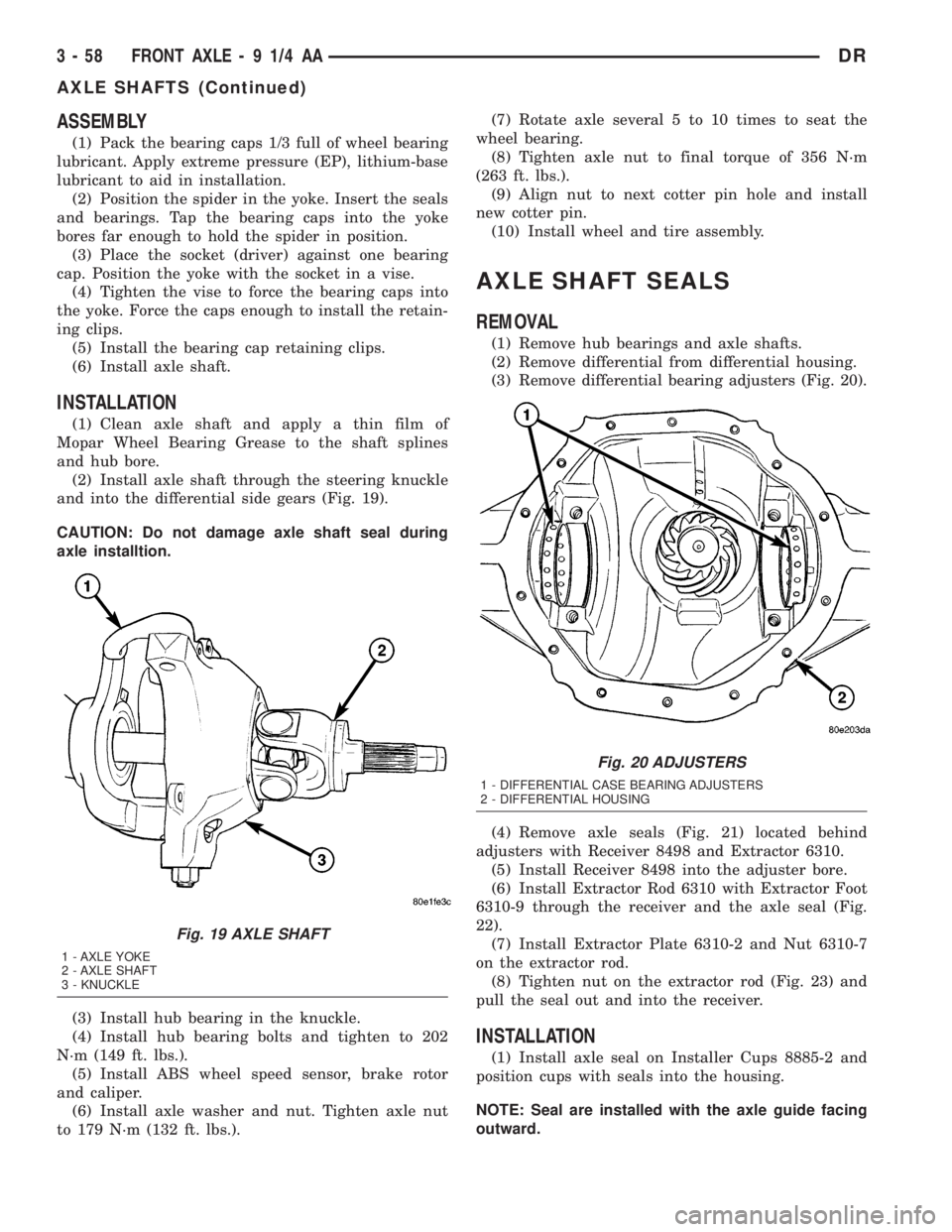
(2) Install axle shaft through the steering knuckle
and into the differential side gears (Fig. 19).
CAUTION: Do not damage axle shaft seal during
axle installtion.
(3) Install hub bearing in the knuckle.
(4) Install hub bearing bolts and tighten to 202
N´m (149 ft. lbs.).
(5) Install ABS wheel speed sensor, brake rotor
and caliper.
(6) Install axle washer and nut. Tighten axle nut
to 179 N´m (132 ft. lbs.).(7) Rotate axle several 5 to 10 times to seat the
wheel bearing.
(8) Tighten axle nut to final torque of 356 N´m
(263 ft. lbs.).
(9) Align nut to next cotter pin hole and install
new cotter pin.
(10) Install wheel and tire assembly.
AXLE SHAFT SEALS
REMOVAL
(1) Remove hub bearings and axle shafts.
(2) Remove differential from differential housing.
(3) Remove differential bearing adjusters (Fig. 20).
(4) Remove axle seals (Fig. 21) located behind
adjusters with Receiver 8498 and Extractor 6310.
(5) Install Receiver 8498 into the adjuster bore.
(6) Install Extractor Rod 6310 with Extractor Foot
6310-9 through the receiver and the axle seal (Fig.
22).
(7) Install Extractor Plate 6310-2 and Nut 6310-7
on the extractor rod.
(8) Tighten nut on the extractor rod (Fig. 23) and
pull the seal out and into the receiver.
INSTALLATION
(1) Install axle seal on Installer Cups 8885-2 and
position cups with seals into the housing.
NOTE: Seal are installed with the axle guide facing
outward.
Fig. 19 AXLE SHAFT
1 - AXLE YOKE
2 - AXLE SHAFT
3 - KNUCKLE
Fig. 20 ADJUSTERS
1 - DIFFERENTIAL CASE BEARING ADJUSTERS
2 - DIFFERENTIAL HOUSING
3 - 58 FRONT AXLE - 9 1/4 AADR
AXLE SHAFTS (Continued)
Page 147 of 2895
REMOVAL
(1) Raise and support the vehicle.
(2) Position a lifting device under the axle.
(3) Secure axle to device.
(4) Remove wheels and tires assemblies.
(5) Remove RWAL sensor from the differential
housing.
(6) Remove brake hose at the axle junction block.
(7) Disconnect parking brake cables and cable
brackets.
(8) Remove brake calipers and rotors.
(9) Remove axle vent hose.
(10) Mark propeller shaft and companion flange
for installation alignment reference.
(11) Remove propeller shaft.
(12) Remove shock absorbers from axle.
(13) Remove U-bolets from axle.
(14) Separate the axle from the vehicle.
INSTALLATION
(1) Raise axle with lifting device and align to the
leaf spring centering bolts.
(2) Install axle U-bolts and tighten to 149 N´m
(110 ft. lbs.).
(3) Install shock absorbers to axle and tighten to
specification.
(4) Install the RWAL sensor to the differential
housing.
(5) Connect the parking brake cables and cable
brackets.
(6) Install brake rotors and calipers.
(7) Connect brake hose to the axle junction block.
(8) Install axle vent hose.
(9) Align propeller shaft and pinion companion
flange reference marks and tighten companion flange
bolts to 115 N´m (85 ft. lbs.).
(10) Install the wheels and tires.
(11) Fill differential to specifications.
(12) Remove lifting device from axle and lower the
vehicle.
ADJUSTMENTS
Ring gear and pinion are supplied as matched sets
only. The identifying numbers for the ring gear and
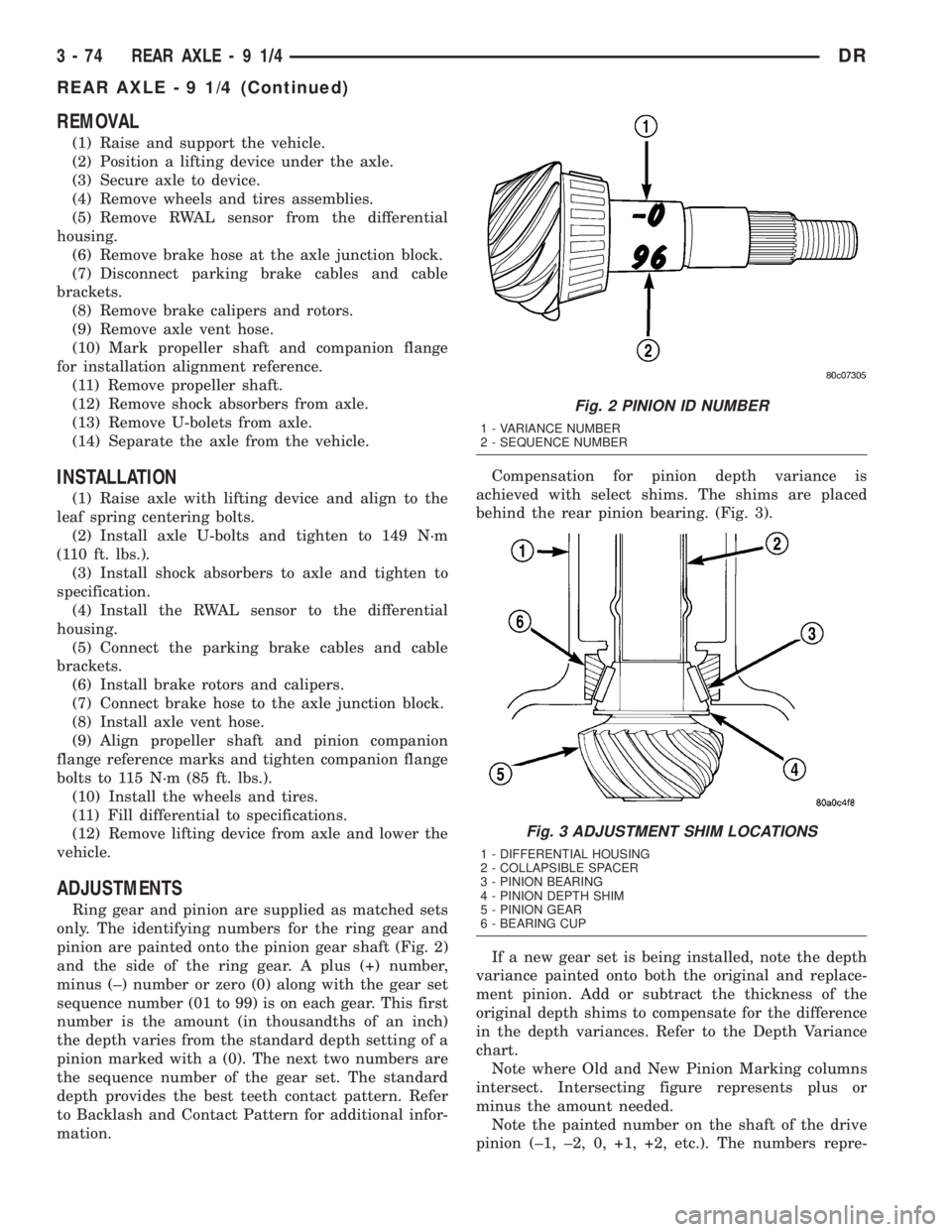
pinion are painted onto the pinion gear shaft (Fig. 2)
and the side of the ring gear. A plus (+) number,
minus (±) number or zero (0) along with the gear set
sequence number (01 to 99) is on each gear. This first
number is the amount (in thousandths of an inch)
the depth varies from the standard depth setting of a
pinion marked with a (0). The next two numbers are
the sequence number of the gear set. The standard
depth provides the best teeth contact pattern. Refer
to Backlash and Contact Pattern for additional infor-
mation.Compensation for pinion depth variance is
achieved with select shims. The shims are placed
behind the rear pinion bearing. (Fig. 3).
If a new gear set is being installed, note the depth
variance painted onto both the original and replace-
ment pinion. Add or subtract the thickness of the
original depth shims to compensate for the difference
in the depth variances. Refer to the Depth Variance
chart.
Note where Old and New Pinion Marking columns
intersect. Intersecting figure represents plus or
minus the amount needed.
Note the painted number on the shaft of the drive
pinion (±1, ±2, 0, +1, +2, etc.). The numbers repre-
Fig. 2 PINION ID NUMBER
1 - VARIANCE NUMBER
2 - SEQUENCE NUMBER
Fig. 3 ADJUSTMENT SHIM LOCATIONS
1 - DIFFERENTIAL HOUSING
2 - COLLAPSIBLE SPACER
3 - PINION BEARING
4 - PINION DEPTH SHIM
5 - PINION GEAR
6 - BEARING CUP
3 - 74 REAR AXLE-91/4DR
REAR AXLE - 9 1/4 (Continued)
Page 160 of 2895
(2) Remove differential cover and drain the lubri-
cant.
(3) Clean housing cavity with flushing oil, light
engine oil or a lint free cloth.
NOTE: Do not use steam, kerosene or gasoline to
clean the housing.
(4) Remove axle shafts.
(5) Remove RWAL/ABS sensor from housing.
NOTE: Side play resulting from bearing races being
loose on case hubs requires replacement of the dif-
ferential case.
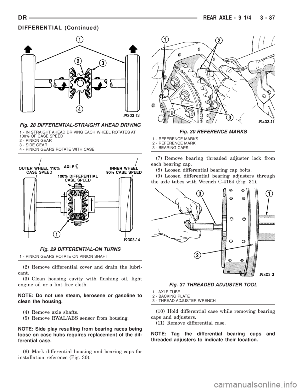
(6) Mark differential housing and bearing caps for
installation reference (Fig. 30).(7) Remove bearing threaded adjuster lock from
each bearing cap.
(8) Loosen differential bearing cap bolts.
(9) Loosen differential bearing adjusters through
the axle tubes with Wrench C-4164 (Fig. 31).
(10) Hold differential case while removing bearing
caps and adjusters.
(11) Remove differential case.
NOTE: Tag the differential bearing cups and
threaded adjusters to indicate their location.
Fig. 28 DIFFERENTIAL-STRAIGHT AHEAD DRIVING
1 - IN STRAIGHT AHEAD DRIVING EACH WHEEL ROTATES AT
100% OF CASE SPEED
2 - PINION GEAR
3 - SIDE GEAR
4 - PINION GEARS ROTATE WITH CASE
Fig. 29 DIFFERENTIAL-ON TURNS
1 - PINION GEARS ROTATE ON PINION SHAFT
Fig. 30 REFERENCE MARKS
1 - REFERENCE MARKS
2 - REFERENCE MARK
3 - BEARING CAPS
Fig. 31 THREADED ADJUSTER TOOL
1 - AXLE TUBE
2 - BACKING PLATE
3 - THREAD ADJUSTER WRENCH
DRREAR AXLE - 9 1/4 3 - 87
DIFFERENTIAL (Continued)
Page 176 of 2895
Condition Possible Causes Correction
Gear Teeth Broke 1. Overloading. 1. Replace gears. Examine other
gears and bearings for possible
damage.
2. Erratic clutch operation. 2. Replace gears and examine the
remaining parts for damage. Avoid
erratic clutch operation.
3. Ice-spotted pavement. 3. Replace gears and examine
remaining parts for damage.
4. Improper adjustments. 4. Replace gears and examine
remaining parts for damage. Ensure
ring gear backlash is correct.
Axle Noise 1. Insufficient lubricant. 1. Fill differential with the correct
fluid type and quantity.
2. Improper ring gear and pinion
adjustment.2. Check ring gear and pinion
contact pattern. Adjust backlash or
pinion depth.
3. Unmatched ring gear and pinion. 3. Replace gears with a matched
ring gear and pinion.
4. Worn teeth on ring gear and/or
pinion.4. Replace ring gear and pinion.
5. Loose pinion bearings. 5. Adjust pinion bearing pre-load.
6. Loose differential bearings. 6. Adjust differential bearing
pre-load.
7. Mis-aligned or sprung ring gear. 7. Measure ring gear run-out.
Replace components as necessary.
8. Loose differential bearing cap
bolts.8. Inspect differential components
and replace as necessary. Ensure
that the bearing caps are torqued
tot he proper specification.
9. Housing not machined properly. 9. Replace housing.
REMOVAL
(1) Raise and support the vehicle.
(2) Position a lifting device under the axle.
(3) Secure axle to device.
(4) Remove wheels and tires assemblies.
(5) Remove RWAL sensor from the differential
housing.
(6) Remove brake hose at the axle junction block
and axle vent hose.
(7) Disconnect parking brake cables and cable
brackets.
(8) Remove brake calipers and rotors.
(9) Mark propeller shaft and companion flange for
installation alignment reference.
(10) Remove propeller shaft.
(11) Remove shock absorbers from axle.
(12) Remove U-bolts from axle.
(13) Separate the axle from the vehicle.
INSTALLATION
(1) Raise axle with lifting device and align to the
leaf spring centering bolts.
(2) Install axle U-bolts and tighten to 149 N´m
(110 ft. lbs.).
(3) Install shock absorbers to axle and tighten to
specification.
(4) Install the RWAL sensor to the differential
housing.
(5) Connect the parking brake cables and cable
brackets.
(6) Install brake calipers.
(7) Connect brake hose to the axle junction block
and axle vent hose.
(8) Align propeller shaft and pinion companion
flange reference marks and tighten companion flange
bolts to 115 N´m (85 ft. lbs.).
(9) Install the wheels and tires.
DRREAR AXLE - 10 1/2 AA 3 - 103
REAR AXLE - 10 1/2 AA (Continued)
Page 203 of 2895
Condition Possible Causes Correction
Gear Teeth Broke 1. Overloading. 1. Replace gears. Examine other
gears and bearings for possible
damage.
2. Erratic clutch operation. 2. Replace gears and examine the
remaining parts for damage. Avoid
erratic clutch operation.
3. Ice-spotted pavement. 3. Replace gears and examine
remaining parts for damage.
4. Improper adjustments. 4. Replace gears and examine
remaining parts for damage. Ensure
ring gear backlash is correct.
Axle Noise 1. Insufficient lubricant. 1. Fill differential with the correct
fluid type and quantity.
2. Improper ring gear and pinion
adjustment.2. Check ring gear and pinion
contact pattern. Adjust backlash or
pinion depth.
3. Unmatched ring gear and pinion. 3. Replace gears with a matched
ring gear and pinion.
4. Worn teeth on ring gear and/or
pinion.4. Replace ring gear and pinion.
5. Loose pinion bearings. 5. Adjust pinion bearing pre-load.
6. Loose differential bearings. 6. Adjust differential bearing
pre-load.
7. Mis-aligned or sprung ring gear. 7. Measure ring gear run-out.
Replace components as necessary.
8. Loose differential bearing cap
bolts.8. Inspect differential components
and replace as necessary. Ensure
that the bearing caps are torqued
tot he proper specification.
9. Housing not machined properly. 9. Replace housing.
REMOVAL
(1) Raise and support the vehicle.
(2) Position a lifting device under the axle.
(3) Secure axle to device.
(4) Remove wheels and tires assemblies.
(5) Remove RWAL sensor from the differential
housing.
(6) Remove brake hose at the axle junction block
and axle vent hose.
(7) Disconnect parking brake cables and cable
brackets.
(8) Remove brake calipers.
(9) Mark propeller shaft and companion flange for
installation alignment reference.
(10) Remove propeller shaft.
(11) Remove shock absorbers from axle.
(12) Remove U-bolets from axle.
(13) Separate the axle from the vehicle.
INSTALLATION
(1) Raise axle with lifting device and align to the
leaf spring centering bolts.
(2) Install axle U-bolts and tighten to 149 N´m
(110 ft. lbs.).
(3) Install shock absorbers to axle and tighten to
specification.
(4) Install the RWAL sensor to the differential
housing.
(5) Connect the parking brake cables and cable
brackets.
(6) Connect brake hose to the axle junction block
and axle vent hose.
(7) Align propeller shaft and pinion companion
flange reference marks and tighten companion flange
bolts to 115 N´m (85 ft. lbs.).
(8) Install the wheels and tires.
(9) Fill differential to specifications.
3 - 130 REAR AXLE - 11 1/2 AADR
REAR AXLE - 11 1/2 AA (Continued)
Page 236 of 2895
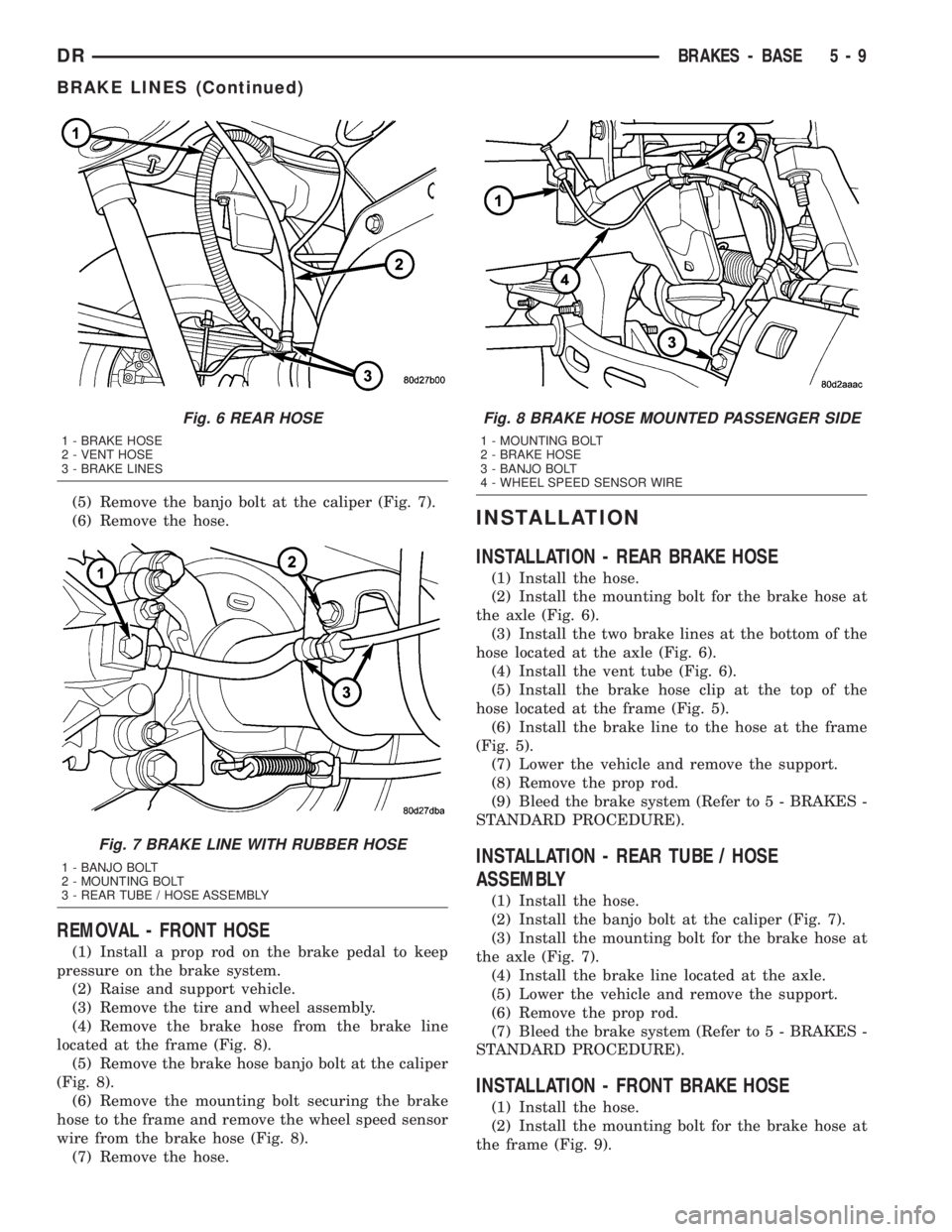
(5) Remove the banjo bolt at the caliper (Fig. 7).
(6) Remove the hose.
REMOVAL - FRONT HOSE
(1) Install a prop rod on the brake pedal to keep
pressure on the brake system.
(2) Raise and support vehicle.
(3) Remove the tire and wheel assembly.
(4) Remove the brake hose from the brake line
located at the frame (Fig. 8).
(5) Remove the brake hose banjo bolt at the caliper
(Fig. 8).
(6) Remove the mounting bolt securing the brake
hose to the frame and remove the wheel speed sensor
wire from the brake hose (Fig. 8).
(7) Remove the hose.
INSTALLATION
INSTALLATION - REAR BRAKE HOSE
(1) Install the hose.
(2) Install the mounting bolt for the brake hose at
the axle (Fig. 6).
(3) Install the two brake lines at the bottom of the
hose located at the axle (Fig. 6).
(4) Install the vent tube (Fig. 6).
(5) Install the brake hose clip at the top of the
hose located at the frame (Fig. 5).
(6) Install the brake line to the hose at the frame
(Fig. 5).
(7) Lower the vehicle and remove the support.
(8) Remove the prop rod.
(9) Bleed the brake system (Refer to 5 - BRAKES -
STANDARD PROCEDURE).
INSTALLATION - REAR TUBE / HOSE
ASSEMBLY
(1) Install the hose.
(2) Install the banjo bolt at the caliper (Fig. 7).
(3) Install the mounting bolt for the brake hose at
the axle (Fig. 7).
(4) Install the brake line located at the axle.
(5) Lower the vehicle and remove the support.
(6) Remove the prop rod.
(7) Bleed the brake system (Refer to 5 - BRAKES -
STANDARD PROCEDURE).
INSTALLATION - FRONT BRAKE HOSE
(1) Install the hose.
(2) Install the mounting bolt for the brake hose at
the frame (Fig. 9).
Fig. 6 REAR HOSE
1 - BRAKE HOSE
2 - VENT HOSE
3 - BRAKE LINES
Fig. 7 BRAKE LINE WITH RUBBER HOSE
1 - BANJO BOLT
2 - MOUNTING BOLT
3 - REAR TUBE / HOSE ASSEMBLY
Fig. 8 BRAKE HOSE MOUNTED PASSENGER SIDE
1 - MOUNTING BOLT
2 - BRAKE HOSE
3 - BANJO BOLT
4 - WHEEL SPEED SENSOR WIRE
DRBRAKES - BASE 5 - 9
BRAKE LINES (Continued)
Page 237 of 2895
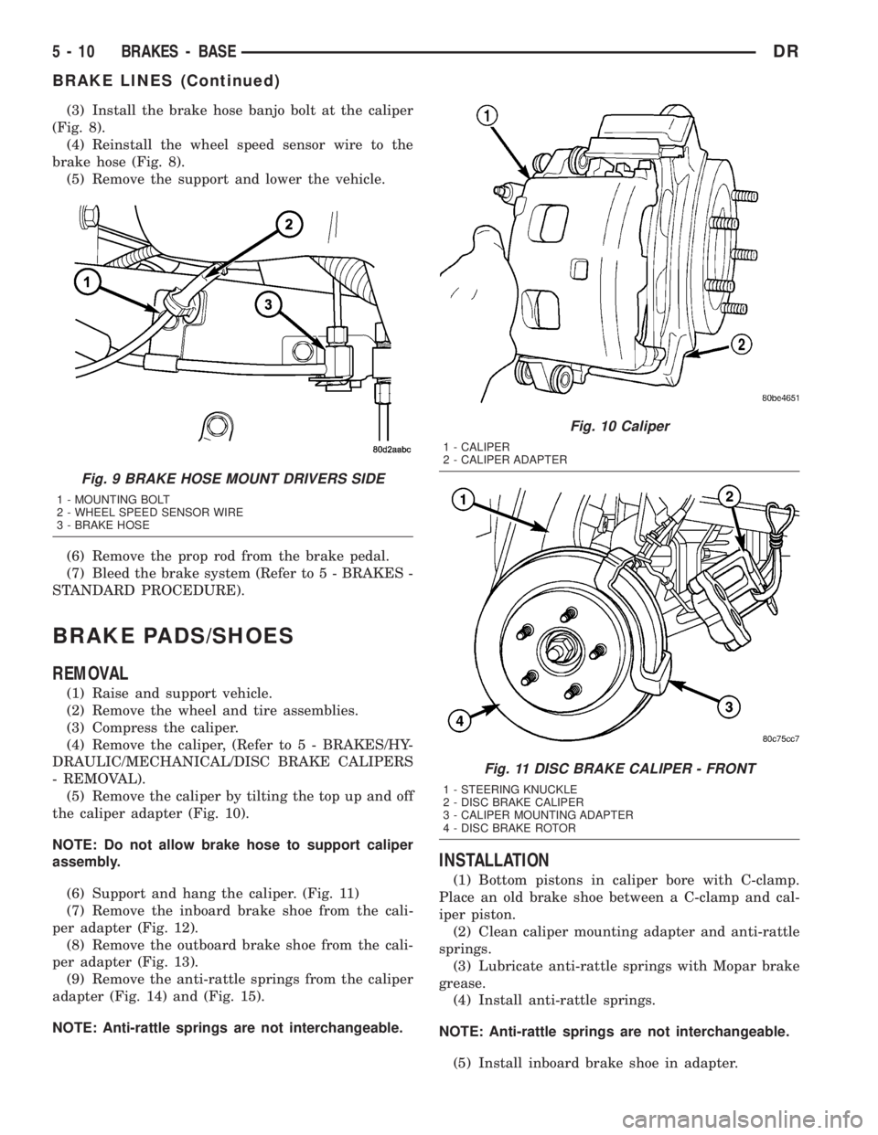
(3) Install the brake hose banjo bolt at the caliper
(Fig. 8).
(4) Reinstall the wheel speed sensor wire to the
brake hose (Fig. 8).
(5) Remove the support and lower the vehicle.
(6) Remove the prop rod from the brake pedal.
(7) Bleed the brake system (Refer to 5 - BRAKES -
STANDARD PROCEDURE).
BRAKE PADS/SHOES
REMOVAL
(1) Raise and support vehicle.
(2) Remove the wheel and tire assemblies.
(3) Compress the caliper.
(4) Remove the caliper, (Refer to 5 - BRAKES/HY-
DRAULIC/MECHANICAL/DISC BRAKE CALIPERS
- REMOVAL).
(5) Remove the caliper by tilting the top up and off
the caliper adapter (Fig. 10).
NOTE: Do not allow brake hose to support caliper
assembly.
(6) Support and hang the caliper. (Fig. 11)
(7) Remove the inboard brake shoe from the cali-
per adapter (Fig. 12).
(8) Remove the outboard brake shoe from the cali-
per adapter (Fig. 13).
(9) Remove the anti-rattle springs from the caliper
adapter (Fig. 14) and (Fig. 15).
NOTE: Anti-rattle springs are not interchangeable.
INSTALLATION
(1) Bottom pistons in caliper bore with C-clamp.
Place an old brake shoe between a C-clamp and cal-
iper piston.
(2) Clean caliper mounting adapter and anti-rattle
springs.
(3) Lubricate anti-rattle springs with Mopar brake
grease.
(4) Install anti-rattle springs.
NOTE: Anti-rattle springs are not interchangeable.
(5) Install inboard brake shoe in adapter.
Fig. 9 BRAKE HOSE MOUNT DRIVERS SIDE
1 - MOUNTING BOLT
2 - WHEEL SPEED SENSOR WIRE
3 - BRAKE HOSE
Fig. 10 Caliper
1 - CALIPER
2 - CALIPER ADAPTER
Fig. 11 DISC BRAKE CALIPER - FRONT
1 - STEERING KNUCKLE
2 - DISC BRAKE CALIPER
3 - CALIPER MOUNTING ADAPTER
4 - DISC BRAKE ROTOR
5 - 10 BRAKES - BASEDR
BRAKE LINES (Continued)
Page 266 of 2895
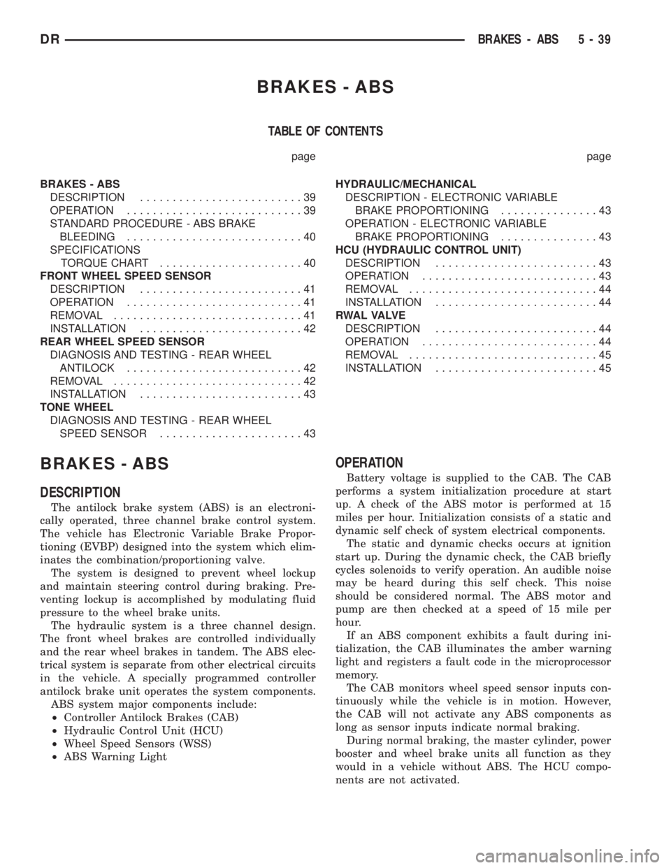
BRAKES - ABS
TABLE OF CONTENTS
page page
BRAKES - ABS
DESCRIPTION.........................39
OPERATION...........................39
STANDARD PROCEDURE - ABS BRAKE
BLEEDING...........................40
SPECIFICATIONS
TORQUE CHART......................40
FRONT WHEEL SPEED SENSOR
DESCRIPTION.........................41
OPERATION...........................41
REMOVAL.............................41
INSTALLATION.........................42
REAR WHEEL SPEED SENSOR
DIAGNOSIS AND TESTING - REAR WHEEL
ANTILOCK...........................42
REMOVAL.............................42
INSTALLATION.........................43
TONE WHEEL
DIAGNOSIS AND TESTING - REAR WHEEL
SPEED SENSOR......................43HYDRAULIC/MECHANICAL
DESCRIPTION - ELECTRONIC VARIABLE
BRAKE PROPORTIONING...............43
OPERATION - ELECTRONIC VARIABLE
BRAKE PROPORTIONING...............43
HCU (HYDRAULIC CONTROL UNIT)
DESCRIPTION.........................43
OPERATION...........................43
REMOVAL.............................44
INSTALLATION.........................44
R WA L VA LV E
DESCRIPTION.........................44
OPERATION...........................44
REMOVAL.............................45
INSTALLATION.........................45
BRAKES - ABS
DESCRIPTION
The antilock brake system (ABS) is an electroni-
cally operated, three channel brake control system.
The vehicle has Electronic Variable Brake Propor-
tioning (EVBP) designed into the system which elim-
inates the combination/proportioning valve.
The system is designed to prevent wheel lockup
and maintain steering control during braking. Pre-
venting lockup is accomplished by modulating fluid
pressure to the wheel brake units.
The hydraulic system is a three channel design.
The front wheel brakes are controlled individually
and the rear wheel brakes in tandem. The ABS elec-
trical system is separate from other electrical circuits
in the vehicle. A specially programmed controller
antilock brake unit operates the system components.
ABS system major components include:
²Controller Antilock Brakes (CAB)
²Hydraulic Control Unit (HCU)
²Wheel Speed Sensors (WSS)
²ABS Warning Light
OPERATION
Battery voltage is supplied to the CAB. The CAB
performs a system initialization procedure at start
up. A check of the ABS motor is performed at 15
miles per hour. Initialization consists of a static and
dynamic self check of system electrical components.
The static and dynamic checks occurs at ignition
start up. During the dynamic check, the CAB briefly
cycles solenoids to verify operation. An audible noise
may be heard during this self check. This noise
should be considered normal. The ABS motor and
pump are then checked at a speed of 15 mile per
hour.
If an ABS component exhibits a fault during ini-
tialization, the CAB illuminates the amber warning
light and registers a fault code in the microprocessor
memory.
The CAB monitors wheel speed sensor inputs con-
tinuously while the vehicle is in motion. However,
the CAB will not activate any ABS components as
long as sensor inputs indicate normal braking.
During normal braking, the master cylinder, power
booster and wheel brake units all function as they
would in a vehicle without ABS. The HCU compo-
nents are not activated.
DRBRAKES - ABS 5 - 39
Page 267 of 2895
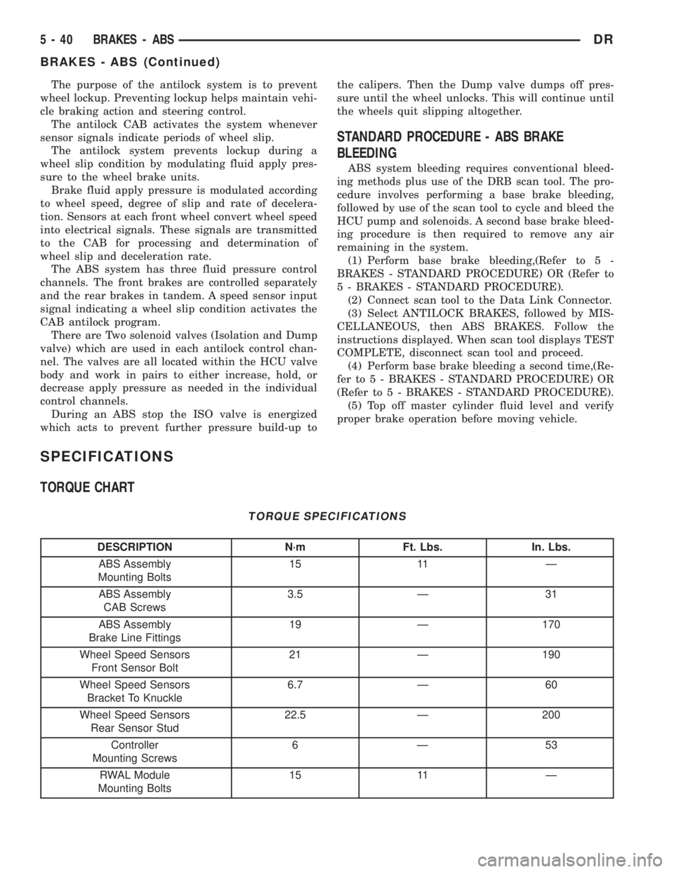
The purpose of the antilock system is to prevent
wheel lockup. Preventing lockup helps maintain vehi-
cle braking action and steering control.
The antilock CAB activates the system whenever
sensor signals indicate periods of wheel slip.
The antilock system prevents lockup during a
wheel slip condition by modulating fluid apply pres-
sure to the wheel brake units.
Brake fluid apply pressure is modulated according
to wheel speed, degree of slip and rate of decelera-
tion. Sensors at each front wheel convert wheel speed
into electrical signals. These signals are transmitted
to the CAB for processing and determination of
wheel slip and deceleration rate.
The ABS system has three fluid pressure control
channels. The front brakes are controlled separately
and the rear brakes in tandem. A speed sensor input
signal indicating a wheel slip condition activates the
CAB antilock program.
There are Two solenoid valves (Isolation and Dump
valve) which are used in each antilock control chan-
nel. The valves are all located within the HCU valve
body and work in pairs to either increase, hold, or
decrease apply pressure as needed in the individual
control channels.
During an ABS stop the ISO valve is energized
which acts to prevent further pressure build-up tothe calipers. Then the Dump valve dumps off pres-
sure until the wheel unlocks. This will continue until
the wheels quit slipping altogether.
STANDARD PROCEDURE - ABS BRAKE
BLEEDING
ABS system bleeding requires conventional bleed-
ing methods plus use of the DRB scan tool. The pro-
cedure involves performing a base brake bleeding,
followed by use of the scan tool to cycle and bleed the
HCU pump and solenoids. A second base brake bleed-
ing procedure is then required to remove any air
remaining in the system.
(1) Perform base brake bleeding,(Refer to 5 -
BRAKES - STANDARD PROCEDURE) OR (Refer to
5 - BRAKES - STANDARD PROCEDURE).
(2) Connect scan tool to the Data Link Connector.
(3) Select ANTILOCK BRAKES, followed by MIS-
CELLANEOUS, then ABS BRAKES. Follow the
instructions displayed. When scan tool displays TEST
COMPLETE, disconnect scan tool and proceed.
(4) Perform base brake bleeding a second time,(Re-
fer to 5 - BRAKES - STANDARD PROCEDURE) OR
(Refer to 5 - BRAKES - STANDARD PROCEDURE).
(5) Top off master cylinder fluid level and verify
proper brake operation before moving vehicle.
SPECIFICATIONS
TORQUE CHART
TORQUE SPECIFICATIONS
DESCRIPTION N´m Ft. Lbs. In. Lbs.
ABS Assembly
Mounting Bolts15 11 Ð
ABS Assembly
CAB Screws3.5 Ð 31
ABS Assembly
Brake Line Fittings19 Ð 170
Wheel Speed Sensors
Front Sensor Bolt21 Ð 190
Wheel Speed Sensors
Bracket To Knuckle6.7 Ð 60
Wheel Speed Sensors
Rear Sensor Stud22.5 Ð 200
Controller
Mounting Screws6Ð53
RWAL Module
Mounting Bolts15 11 Ð
5 - 40 BRAKES - ABSDR
BRAKES - ABS (Continued)