spark plugs replace DODGE RAM 2003 Service Owner's Guide
[x] Cancel search | Manufacturer: DODGE, Model Year: 2003, Model line: RAM, Model: DODGE RAM 2003Pages: 2895, PDF Size: 83.15 MB
Page 1603 of 2895
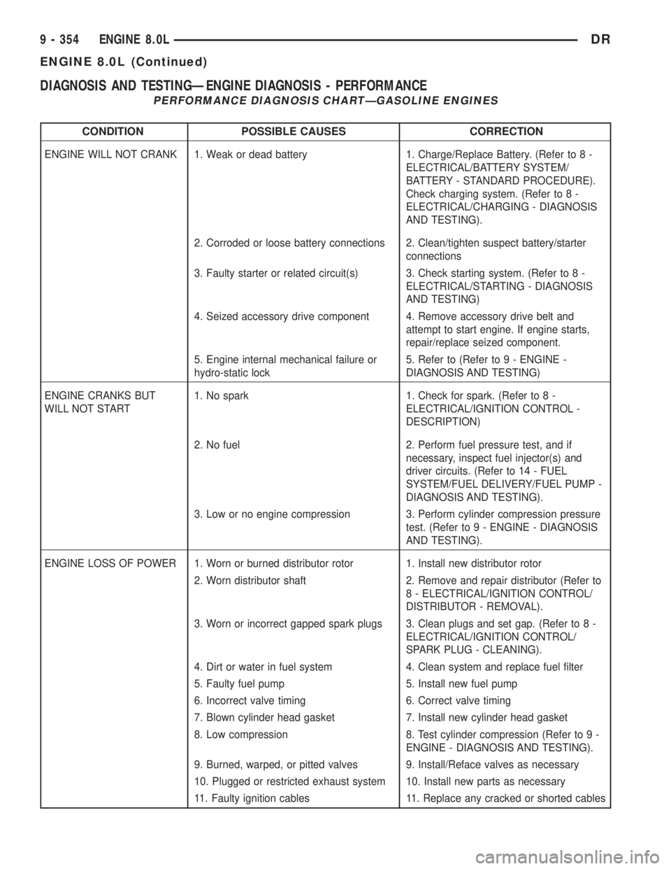
DIAGNOSIS AND TESTINGÐENGINE DIAGNOSIS - PERFORMANCE
PERFORMANCE DIAGNOSIS CHARTÐGASOLINE ENGINES
CONDITION POSSIBLE CAUSES CORRECTION
ENGINE WILL NOT CRANK 1. Weak or dead battery 1. Charge/Replace Battery. (Refer to 8 -
ELECTRICAL/BATTERY SYSTEM/
BATTERY - STANDARD PROCEDURE).
Check charging system. (Refer to 8 -
ELECTRICAL/CHARGING - DIAGNOSIS
AND TESTING).
2. Corroded or loose battery connections 2. Clean/tighten suspect battery/starter
connections
3. Faulty starter or related circuit(s) 3. Check starting system. (Refer to 8 -
ELECTRICAL/STARTING - DIAGNOSIS
AND TESTING)
4. Seized accessory drive component 4. Remove accessory drive belt and
attempt to start engine. If engine starts,
repair/replace seized component.
5. Engine internal mechanical failure or
hydro-static lock5. Refer to (Refer to 9 - ENGINE -
DIAGNOSIS AND TESTING)
ENGINE CRANKS BUT
WILL NOT START1. No spark 1. Check for spark. (Refer to 8 -
ELECTRICAL/IGNITION CONTROL -
DESCRIPTION)
2. No fuel 2. Perform fuel pressure test, and if
necessary, inspect fuel injector(s) and
driver circuits. (Refer to 14 - FUEL
SYSTEM/FUEL DELIVERY/FUEL PUMP -
DIAGNOSIS AND TESTING).
3. Low or no engine compression 3. Perform cylinder compression pressure
test. (Refer to 9 - ENGINE - DIAGNOSIS
AND TESTING).
ENGINE LOSS OF POWER 1. Worn or burned distributor rotor 1. Install new distributor rotor
2. Worn distributor shaft 2. Remove and repair distributor (Refer to
8 - ELECTRICAL/IGNITION CONTROL/
DISTRIBUTOR - REMOVAL).
3. Worn or incorrect gapped spark plugs 3. Clean plugs and set gap. (Refer to 8 -
ELECTRICAL/IGNITION CONTROL/
SPARK PLUG - CLEANING).
4. Dirt or water in fuel system 4. Clean system and replace fuel filter
5. Faulty fuel pump 5. Install new fuel pump
6. Incorrect valve timing 6. Correct valve timing
7. Blown cylinder head gasket 7. Install new cylinder head gasket
8. Low compression 8. Test cylinder compression (Refer to 9 -
ENGINE - DIAGNOSIS AND TESTING).
9. Burned, warped, or pitted valves 9. Install/Reface valves as necessary
10. Plugged or restricted exhaust system 10. Install new parts as necessary
11. Faulty ignition cables 11. Replace any cracked or shorted cables
9 - 354 ENGINE 8.0LDR
ENGINE 8.0L (Continued)
Page 1604 of 2895
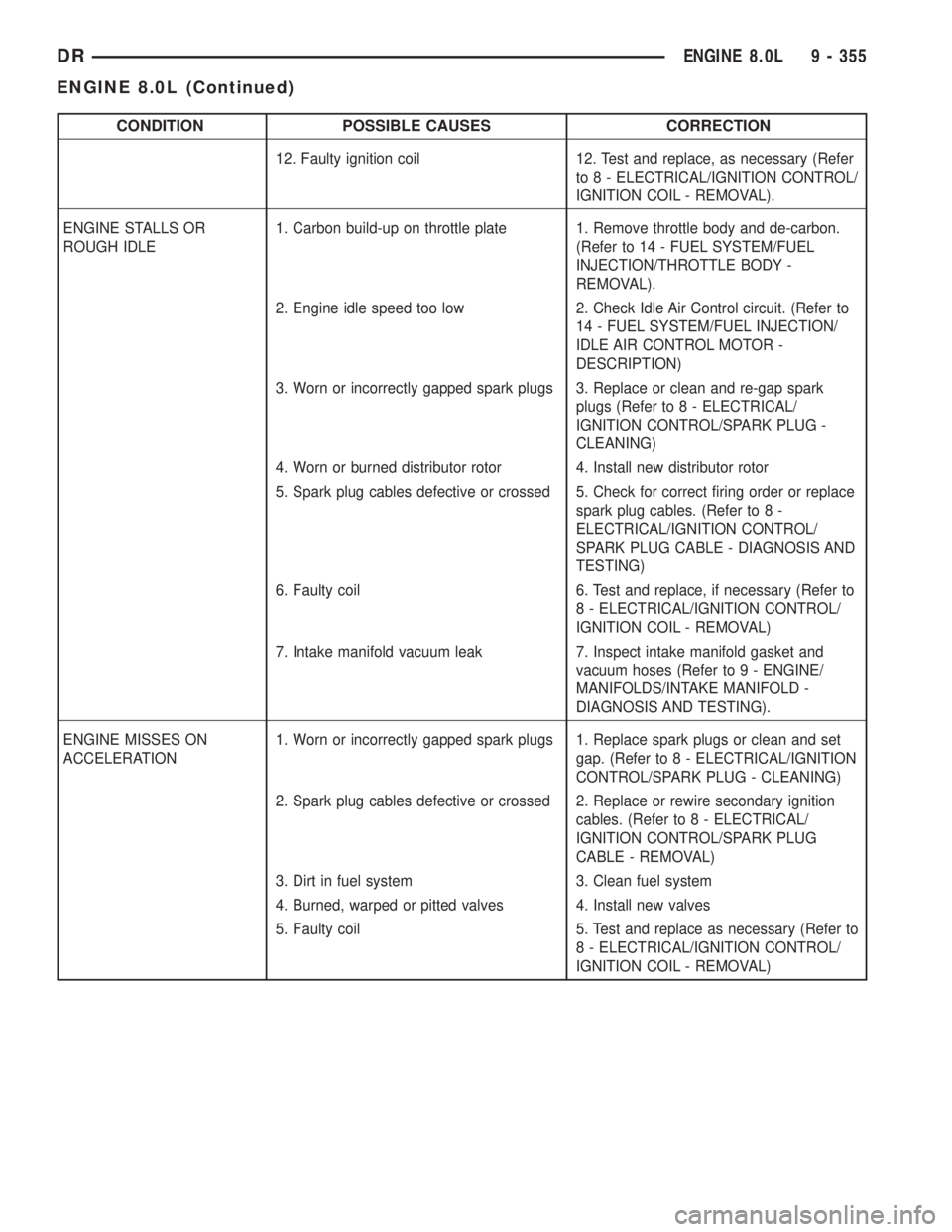
CONDITION POSSIBLE CAUSES CORRECTION
12. Faulty ignition coil 12. Test and replace, as necessary (Refer
to 8 - ELECTRICAL/IGNITION CONTROL/
IGNITION COIL - REMOVAL).
ENGINE STALLS OR
ROUGH IDLE1. Carbon build-up on throttle plate 1. Remove throttle body and de-carbon.
(Refer to 14 - FUEL SYSTEM/FUEL
INJECTION/THROTTLE BODY -
REMOVAL).
2. Engine idle speed too low 2. Check Idle Air Control circuit. (Refer to
14 - FUEL SYSTEM/FUEL INJECTION/
IDLE AIR CONTROL MOTOR -
DESCRIPTION)
3. Worn or incorrectly gapped spark plugs 3. Replace or clean and re-gap spark
plugs (Refer to 8 - ELECTRICAL/
IGNITION CONTROL/SPARK PLUG -
CLEANING)
4. Worn or burned distributor rotor 4. Install new distributor rotor
5. Spark plug cables defective or crossed 5. Check for correct firing order or replace
spark plug cables. (Refer to 8 -
ELECTRICAL/IGNITION CONTROL/
SPARK PLUG CABLE - DIAGNOSIS AND
TESTING)
6. Faulty coil 6. Test and replace, if necessary (Refer to
8 - ELECTRICAL/IGNITION CONTROL/
IGNITION COIL - REMOVAL)
7. Intake manifold vacuum leak 7. Inspect intake manifold gasket and
vacuum hoses (Refer to 9 - ENGINE/
MANIFOLDS/INTAKE MANIFOLD -
DIAGNOSIS AND TESTING).
ENGINE MISSES ON
ACCELERATION1. Worn or incorrectly gapped spark plugs 1. Replace spark plugs or clean and set
gap. (Refer to 8 - ELECTRICAL/IGNITION
CONTROL/SPARK PLUG - CLEANING)
2. Spark plug cables defective or crossed 2. Replace or rewire secondary ignition
cables. (Refer to 8 - ELECTRICAL/
IGNITION CONTROL/SPARK PLUG
CABLE - REMOVAL)
3. Dirt in fuel system 3. Clean fuel system
4. Burned, warped or pitted valves 4. Install new valves
5. Faulty coil 5. Test and replace as necessary (Refer to
8 - ELECTRICAL/IGNITION CONTROL/
IGNITION COIL - REMOVAL)
DRENGINE 8.0L 9 - 355
ENGINE 8.0L (Continued)
Page 1606 of 2895
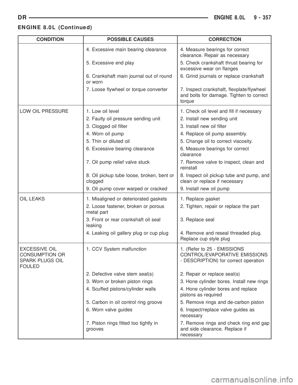
CONDITION POSSIBLE CAUSES CORRECTION
4. Excessive main bearing clearance 4. Measure bearings for correct
clearance. Repair as necessary
5. Excessive end play 5. Check crankshaft thrust bearing for
excessive wear on flanges
6. Crankshaft main journal out of round
or worn6. Grind journals or replace crankshaft
7. Loose flywheel or torque converter 7. Inspect crankshaft, flexplate/flywheel
and bolts for damage. Tighten to correct
torque
LOW OIL PRESSURE 1. Low oil level 1. Check oil level and fill if necessary
2. Faulty oil pressure sending unit 2. Install new sending unit
3. Clogged oil filter 3. Install new oil filter
4. Worn oil pump 4. Replace oil pump assembly.
5. Thin or diluted oil 5. Change oil to correct viscosity.
6. Excessive bearing clearance 6. Measure bearings for correct
clearance
7. Oil pump relief valve stuck 7. Remove valve to inspect, clean and
reinstall
8. Oil pickup tube loose, broken, bent or
clogged8. Inspect oil pickup tube and pump, and
clean or replace if necessary
9. Oil pump cover warped or cracked 9. Install new oil pump
OIL LEAKS 1. Misaligned or deteriorated gaskets 1. Replace gasket
2. Loose fastener, broken or porous
metal part2. Tighten, repair or replace the part
3. Front or rear crankshaft oil seal
leaking3. Replace seal
4. Leaking oil gallery plug or cup plug 4. Remove and reseal threaded plug.
Replace cup style plug
EXCESSIVE OIL
CONSUMPTION OR
SPARK PLUGS OIL
FOULED1. CCV System malfunction 1. (Refer to 25 - EMISSIONS
CONTROL/EVAPORATIVE EMISSIONS
- DESCRIPTION) for correct operation
2. Defective valve stem seal(s) 2. Repair or replace seal(s)
3. Worn or broken piston rings 3. Hone cylinder bores. Install new rings
4. Scuffed pistons/cylinder walls 4. Hone cylinder bores and replace
pistons as required
5. Carbon in oil control ring groove 5. Remove rings and de-carbon piston
6. Worn valve guides 6. Inspect/replace valve guides as
necessary
7. Piston rings fitted too tightly in
grooves7. Remove rings and check ring end gap
and side clearance. Replace if
necessary
DRENGINE 8.0L 9 - 357
ENGINE 8.0L (Continued)
Page 1607 of 2895
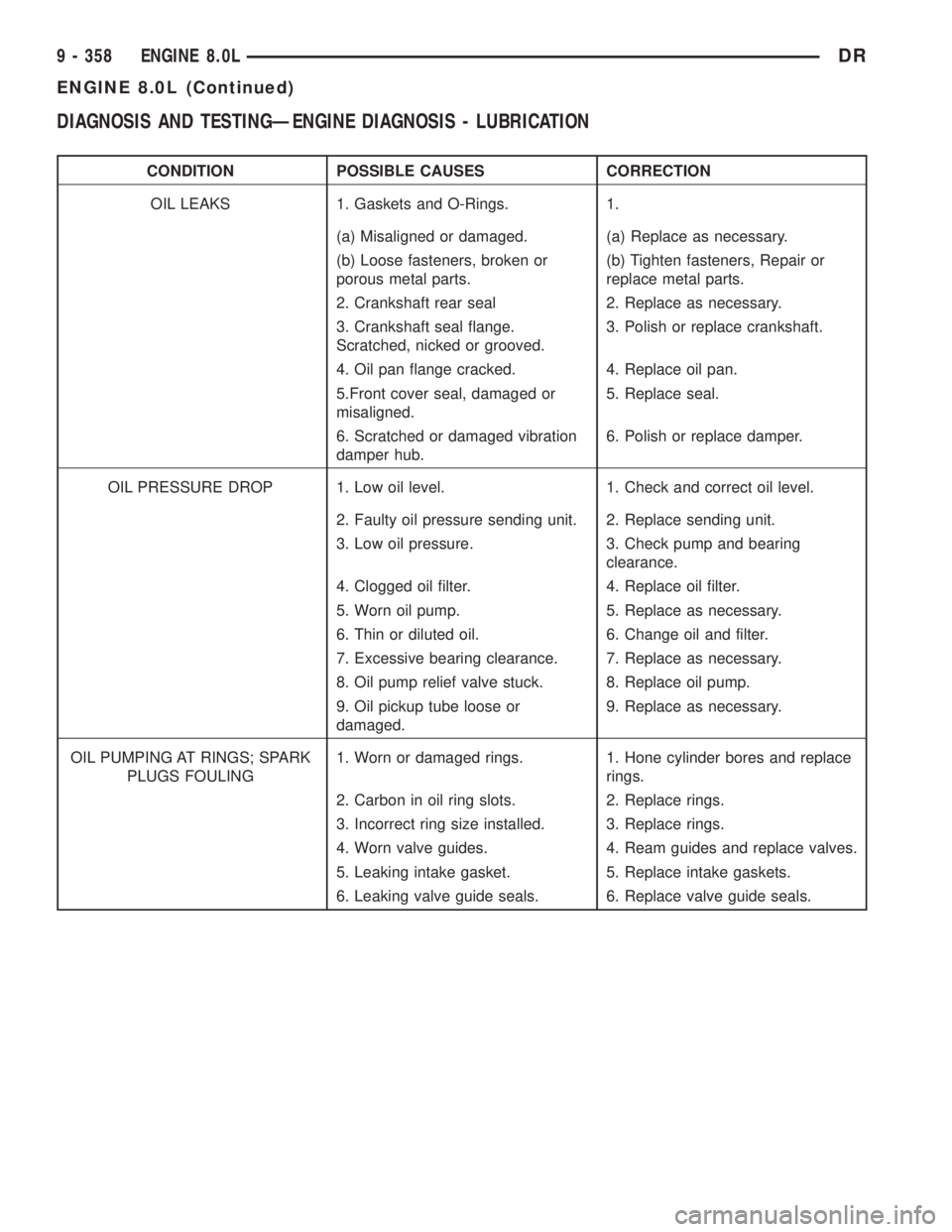
DIAGNOSIS AND TESTINGÐENGINE DIAGNOSIS - LUBRICATION
CONDITION POSSIBLE CAUSES CORRECTION
OIL LEAKS 1. Gaskets and O-Rings. 1.
(a) Misaligned or damaged. (a) Replace as necessary.
(b) Loose fasteners, broken or
porous metal parts.(b) Tighten fasteners, Repair or
replace metal parts.
2. Crankshaft rear seal 2. Replace as necessary.
3. Crankshaft seal flange.
Scratched, nicked or grooved.3. Polish or replace crankshaft.
4. Oil pan flange cracked. 4. Replace oil pan.
5.Front cover seal, damaged or
misaligned.5. Replace seal.
6. Scratched or damaged vibration
damper hub.6. Polish or replace damper.
OIL PRESSURE DROP 1. Low oil level. 1. Check and correct oil level.
2. Faulty oil pressure sending unit. 2. Replace sending unit.
3. Low oil pressure. 3. Check pump and bearing
clearance.
4. Clogged oil filter. 4. Replace oil filter.
5. Worn oil pump. 5. Replace as necessary.
6. Thin or diluted oil. 6. Change oil and filter.
7. Excessive bearing clearance. 7. Replace as necessary.
8. Oil pump relief valve stuck. 8. Replace oil pump.
9. Oil pickup tube loose or
damaged.9. Replace as necessary.
OIL PUMPING AT RINGS; SPARK
PLUGS FOULING1. Worn or damaged rings. 1. Hone cylinder bores and replace
rings.
2. Carbon in oil ring slots. 2. Replace rings.
3. Incorrect ring size installed. 3. Replace rings.
4. Worn valve guides. 4. Ream guides and replace valves.
5. Leaking intake gasket. 5. Replace intake gaskets.
6. Leaking valve guide seals. 6. Replace valve guide seals.
9 - 358 ENGINE 8.0LDR
ENGINE 8.0L (Continued)
Page 1608 of 2895
DIAGNOSIS AND TESTINGÐCYLINDER
COMPRESSION PRESSURE
The results of a cylinder compression pressure test
can be utilized to diagnose several engine malfunc-
tions.
Ensure the battery is completely charged and the
engine starter motor is in good operating condition.
Otherwise, the indicated compression pressures may
not be valid for diagnosis purposes.
(1) Clean the spark plug recesses with compressed
air.
(2) Remove the spark plugs (Refer to 8 - ELEC-
TRICAL/IGNITION CONTROL/SPARK PLUG -
REMOVAL).
(3) Secure the throttle in the wide-open position.
(4) Disconnect the ignition coil.
(5) Insert a compression pressure gauge and rotate
the engine with the engine starter motor for three
revolutions.
(6) Record the compression pressure on the third
revolution. Continue the test for the remaining cylin-
ders.
(Refer to 9 - ENGINE - SPECIFICATIONS) for the
correct engine compression pressures.
DIAGNOSIS AND TESTING - CYLINDER
COMBUSTION PRESSURE LEAKAGE
The combustion pressure leakage test provides an
accurate means for determining engine condition.
Combustion pressure leakage testing will detect:
²Exhaust and intake valve leaks (improper seat-
ing)
²Leaks between adjacent cylinders or into water
jacket²Any causes for combustion/compression pressure
loss
WARNING: DO NOT REMOVE THE RADIATOR CAP
WITH THE SYSTEM HOT AND UNDER PRESSURE.
SERIOUS BURNS FROM HOT COOLANT CAN
OCCUR.
Check the coolant level and fill as required. DO
NOT install the radiator cap.
Start and operate the engine until it attains nor-
mal operating temperature, then turn OFF the
engine.
Remove the spark plugs.
Remove the oil filler cap.
Remove the air cleaner.
Calibrate the tester according to the manufactur-
er's instructions. The shop air source for testing
should maintain 483 kPa (70 psi) minimum, 1,379
kPa (200 psi) maximum and 552 kPa (80 psi) recom-
mended.
Perform the test procedure on each cylinder accord-
ing to the tester manufacturer's instructions. While
testing, listen for pressurized air escaping through
the throttle body, tailpipe or oil filler cap opening.
Check for bubbles in the radiator coolant.
All gauge pressure indications should be equal,
with no more than 25% leakage.
FOR EXAMPLE:At 552 kPa (80 psi) input pres-
sure, a minimum of 414 kPa (60 psi) should be main-
tained in the cylinder CYLINDER COMBUSTION
PRESSURE LEAKAGE DIAGNOSIS CHART.
CYLINDER COMBUSTION PRESSURE LEAKAGE DIAGNOSIS CHART
CONDITION POSSIBLE CAUSE CORRECTION
AIR ESCAPES THROUGH
THROTTLE BODYIntake valve bent, burnt, or not
seated properlyInspect valve and valve seat.
Reface or replace, as necessary
AIR ESCAPES THROUGH
TAILPIPEExhaust valve bent, burnt, or not
seated properlyInspect valve and valve seat.
Reface or replace, as necessary
AIR ESCAPES THROUGH
RADIATORHead gasket leaking or cracked
cylinder head or blockRemove cylinder head and inspect.
Replace defective part
MORE THAN 50% LEAKAGE
FROM ADJACENT CYLINDERSHead gasket leaking or crack in
cylinder head or block between
adjacent cylindersRemove cylinder head and inspect.
Replace gasket, head, or block as
necessary
MORE THAN 25% LEAKAGE AND
AIR ESCAPES THROUGH OIL
FILLER CAP OPENING ONLYStuck or broken piston rings;
cracked piston; worn rings and/or
cylinder wallInspect for broken rings or piston.
Measure ring gap and cylinder
diameter, taper and out-of-round.
Replace defective part as necessary
DRENGINE 8.0L 9 - 359
ENGINE 8.0L (Continued)
Page 1619 of 2895
AIR CLEANER ELEMENT
REMOVAL
Filter Element Only
Housing removal is not necessary for element (fil-
ter) replacement.
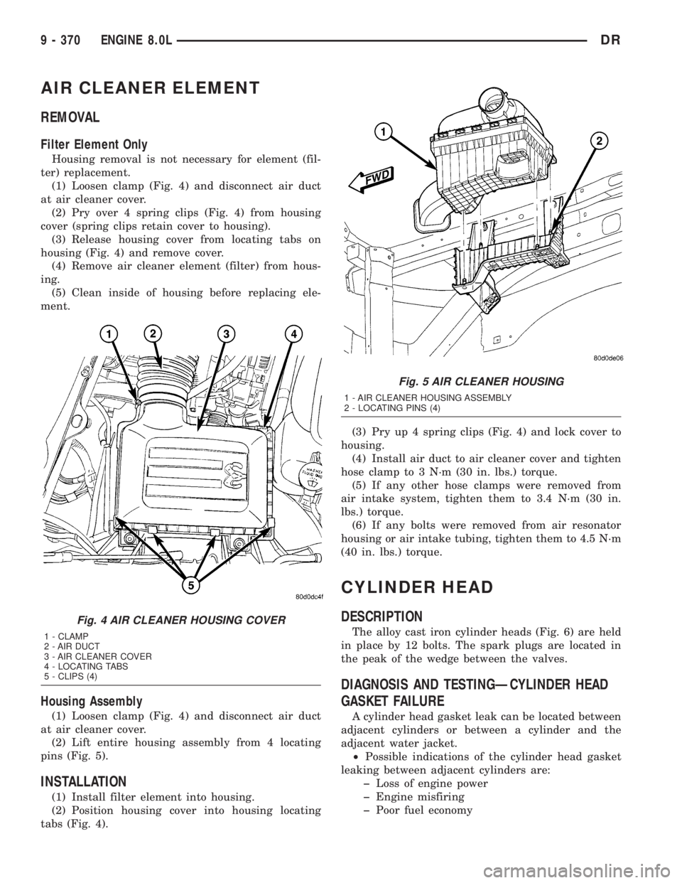
(1) Loosen clamp (Fig. 4) and disconnect air duct
at air cleaner cover.
(2) Pry over 4 spring clips (Fig. 4) from housing
cover (spring clips retain cover to housing).
(3) Release housing cover from locating tabs on
housing (Fig. 4) and remove cover.
(4) Remove air cleaner element (filter) from hous-
ing.
(5) Clean inside of housing before replacing ele-
ment.
Housing Assembly
(1) Loosen clamp (Fig. 4) and disconnect air duct
at air cleaner cover.
(2) Lift entire housing assembly from 4 locating
pins (Fig. 5).
INSTALLATION
(1) Install filter element into housing.
(2) Position housing cover into housing locating
tabs (Fig. 4).(3) Pry up 4 spring clips (Fig. 4) and lock cover to
housing.
(4) Install air duct to air cleaner cover and tighten
hose clamp to 3 N´m (30 in. lbs.) torque.
(5) If any other hose clamps were removed from
air intake system, tighten them to 3.4 N´m (30 in.
lbs.) torque.
(6) If any bolts were removed from air resonator
housing or air intake tubing, tighten them to 4.5 N´m
(40 in. lbs.) torque.
CYLINDER HEAD
DESCRIPTION
The alloy cast iron cylinder heads (Fig. 6) are held
in place by 12 bolts. The spark plugs are located in
the peak of the wedge between the valves.
DIAGNOSIS AND TESTINGÐCYLINDER HEAD
GASKET FAILURE
A cylinder head gasket leak can be located between
adjacent cylinders or between a cylinder and the
adjacent water jacket.
²Possible indications of the cylinder head gasket
leaking between adjacent cylinders are:
þ Loss of engine power
þ Engine misfiring
þ Poor fuel economy
Fig. 4 AIR CLEANER HOUSING COVER
1 - CLAMP
2 - AIR DUCT
3 - AIR CLEANER COVER
4 - LOCATING TABS
5 - CLIPS (4)
Fig. 5 AIR CLEANER HOUSING
1 - AIR CLEANER HOUSING ASSEMBLY
2 - LOCATING PINS (4)
9 - 370 ENGINE 8.0LDR
Page 1621 of 2895
fuel line (Refer to 14 - FUEL SYSTEM/FUEL DELIV-
ERY/QUICK CONNECT FITTING - STANDARD
PROCEDURE).
(9) Disconnect accelerator linkage and if so
equipped, the speed control and transmission kick-
down cables.
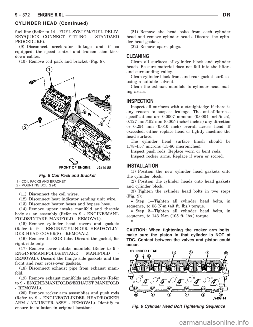
(10) Remove coil pack and bracket (Fig. 8).
(11) Disconnect the coil wires.
(12) Disconnect heat indicator sending unit wire.
(13) Disconnect heater hoses and bypass hose.
(14) Remove upper intake manifold and throttle
body as an assembly (Refer to 9 - ENGINE/MANI-
FOLDS/INTAKE MANIFOLD - REMOVAL).
(15) Remove cylinder head covers and gaskets
(Refer to 9 - ENGINE/CYLINDER HEAD/CYLIN-
DER HEAD COVER(S) - REMOVAL).
(16) Remove the EGR tube. Discard the gasket, for
right side only.
(17) Remove lower intake manifold (Refer to 9 -
ENGINE/MANIFOLDS/INTAKE MANIFOLD -
REMOVAL). Discard the flange side gaskets and the
front and rear cross-over gaskets.
(18) Disconnect exhaust pipe from exhaust mani-
fold.
(19) Remove exhaust manifolds and gaskets (Refer
to 9 - ENGINE/MANIFOLDS/EXHAUST MANIFOLD
- REMOVAL).
(20) Remove rocker arm assemblies and push rods
(Refer to 9 - ENGINE/CYLINDER HEAD/ROCKER
ARM / ADJUSTER ASSY - REMOVAL). Identify to
ensure installation in original locations.(21) Remove the head bolts from each cylinder
head and remove cylinder heads. Discard the cylin-
der head gasket.
(22) Remove spark plugs.
CLEANING
Clean all surfaces of cylinder block and cylinder
heads. Be sure material does not fall into the lifters
and surrounding valley.
Clean cylinder block front and rear gasket surfaces
using a suitable solvent.
Clean the exhaust manifold to cylinder head mat-
ing areas.
INSPECTION
Inspect all surfaces with a straightedge if there is
any reason to suspect leakage. The out-of-flatness
specifications are 0.0007 mm/mm (0.0004 inch/inch),
0.127 mm/152 mm (0.005 inch/6 inches) any direction
or 0.254 mm (0.010 inch) overall across head. If
exceeded, either replace head or lightly machine the
head surface.
The cylinder head surface finish should be
1.78-4.57 microns (15-80 microinches).
Inspect push rods. Replace worn or bent rods.
Inspect rocker arms. Replace if worn or scored.
INSTALLATION
(1) Position the new cylinder head gaskets onto
the cylinder block.
(2) Position the cylinder heads onto head gaskets
and cylinder block.
(3) Tighten the cylinder head bolts in two steps
(Fig. 9):
²Step 1ÐTighten all cylinder head bolts, in
sequence, to 58 N´m (43 ft. lbs.) torque.
²Step 2ÐTighten all cylinder head bolts, in
sequence, to 143 N´m (105 ft. lbs.) torque.
²
CAUTION: When tightening the rocker arm bolts,
make sure the piston in that cylinder is NOT at
TDC. Contact between the valves and piston could
occur.
Fig. 8 Coil Pack and Bracket
1 - COIL PACKS AND BRACKET
2 - MOUNTING BOLTS (4)
Fig. 9 Cylinder Head Bolt Tightening Sequence
9 - 372 ENGINE 8.0LDR
CYLINDER HEAD (Continued)
Page 1629 of 2895
(1) Install the push rods in the same order as
removed.
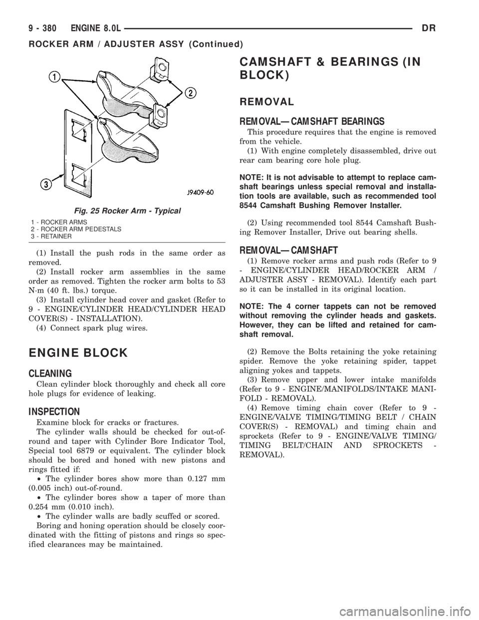
(2) Install rocker arm assemblies in the same
order as removed. Tighten the rocker arm bolts to 53
N´m (40 ft. lbs.) torque.
(3) Install cylinder head cover and gasket (Refer to
9 - ENGINE/CYLINDER HEAD/CYLINDER HEAD
COVER(S) - INSTALLATION).
(4) Connect spark plug wires.
ENGINE BLOCK
CLEANING
Clean cylinder block thoroughly and check all core
hole plugs for evidence of leaking.
INSPECTION
Examine block for cracks or fractures.
The cylinder walls should be checked for out-of-
round and taper with Cylinder Bore Indicator Tool,
Special tool 6879 or equivalent. The cylinder block
should be bored and honed with new pistons and
rings fitted if:
²The cylinder bores show more than 0.127 mm
(0.005 inch) out-of-round.
²The cylinder bores show a taper of more than
0.254 mm (0.010 inch).
²The cylinder walls are badly scuffed or scored.
Boring and honing operation should be closely coor-
dinated with the fitting of pistons and rings so spec-
ified clearances may be maintained.
CAMSHAFT & BEARINGS (IN
BLOCK)
REMOVAL
REMOVALÐCAMSHAFT BEARINGS
This procedure requires that the engine is removed
from the vehicle.
(1) With engine completely disassembled, drive out
rear cam bearing core hole plug.
NOTE: It is not advisable to attempt to replace cam-
shaft bearings unless special removal and installa-
tion tools are available, such as recommended tool
8544 Camshaft Bushing Remover Installer.
(2) Using recommended tool 8544 Camshaft Bush-
ing Remover Installer, Drive out bearing shells.
REMOVALÐCAMSHAFT
(1) Remove rocker arms and push rods (Refer to 9
- ENGINE/CYLINDER HEAD/ROCKER ARM /
ADJUSTER ASSY - REMOVAL). Identify each part
so it can be installed in its original location.
NOTE: The 4 corner tappets can not be removed
without removing the cylinder heads and gaskets.
However, they can be lifted and retained for cam-
shaft removal.
(2) Remove the Bolts retaining the yoke retaining
spider. Remove the yoke retaining spider, tappet
aligning yokes and tappets.
(3) Remove upper and lower intake manifolds
(Refer to 9 - ENGINE/MANIFOLDS/INTAKE MANI-
FOLD - REMOVAL).
(4) Remove timing chain cover (Refer to 9 -
ENGINE/VALVE TIMING/TIMING BELT / CHAIN
COVER(S) - REMOVAL) and timing chain and
sprockets (Refer to 9 - ENGINE/VALVE TIMING/
TIMING BELT/CHAIN AND SPROCKETS -
REMOVAL).
Fig. 25 Rocker Arm - Typical
1 - ROCKER ARMS
2 - ROCKER ARM PEDESTALS
3 - RETAINER
9 - 380 ENGINE 8.0LDR
ROCKER ARM / ADJUSTER ASSY (Continued)
Page 1659 of 2895
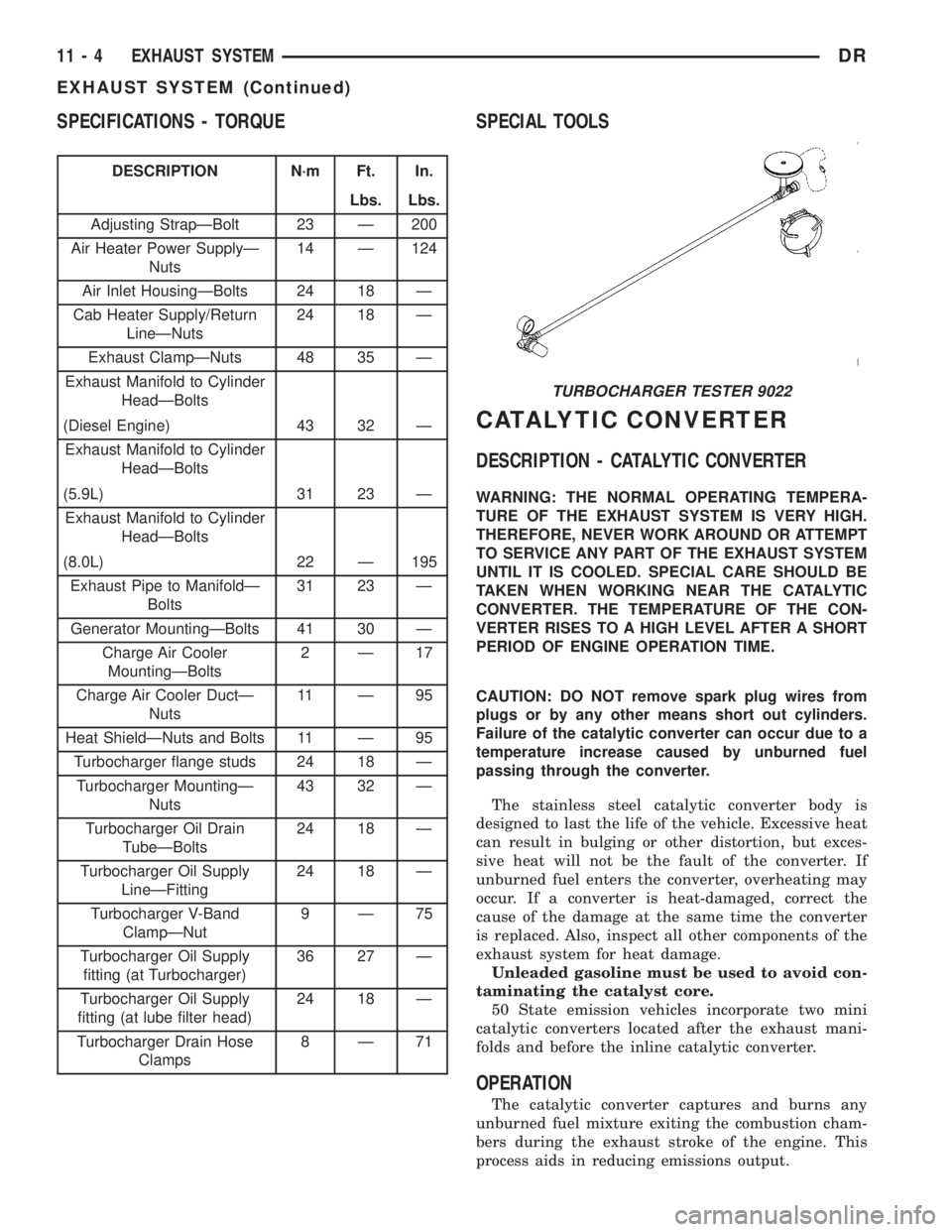
SPECIFICATIONS - TORQUE
DESCRIPTION N´m Ft. In.
Lbs. Lbs.
Adjusting StrapÐBolt 23 Ð 200
Air Heater Power SupplyÐ
Nuts14 Ð 124
Air Inlet HousingÐBolts 24 18 Ð
Cab Heater Supply/Return
LineÐNuts24 18 Ð
Exhaust ClampÐNuts 48 35 Ð
Exhaust Manifold to Cylinder
HeadÐBolts
(Diesel Engine) 43 32 Ð
Exhaust Manifold to Cylinder
HeadÐBolts
(5.9L) 31 23 Ð
Exhaust Manifold to Cylinder
HeadÐBolts
(8.0L) 22 Ð 195
Exhaust Pipe to ManifoldÐ
Bolts31 23 Ð
Generator MountingÐBolts 41 30 Ð
Charge Air Cooler
MountingÐBolts2Ð17
Charge Air Cooler DuctÐ
Nuts11 Ð 9 5
Heat ShieldÐNuts and Bolts 11 Ð 95
Turbocharger flange studs 24 18 Ð
Turbocharger MountingÐ
Nuts43 32 Ð
Turbocharger Oil Drain
TubeÐBolts24 18 Ð
Turbocharger Oil Supply
LineÐFitting24 18 Ð
Turbocharger V-Band
ClampÐNut9Ð75
Turbocharger Oil Supply
fitting (at Turbocharger)36 27 Ð
Turbocharger Oil Supply
fitting (at lube filter head)24 18 Ð
Turbocharger Drain Hose
Clamps8Ð71
SPECIAL TOOLS
CATALYTIC CONVERTER
DESCRIPTION - CATALYTIC CONVERTER
WARNING: THE NORMAL OPERATING TEMPERA-
TURE OF THE EXHAUST SYSTEM IS VERY HIGH.
THEREFORE, NEVER WORK AROUND OR ATTEMPT
TO SERVICE ANY PART OF THE EXHAUST SYSTEM
UNTIL IT IS COOLED. SPECIAL CARE SHOULD BE
TAKEN WHEN WORKING NEAR THE CATALYTIC
CONVERTER. THE TEMPERATURE OF THE CON-
VERTER RISES TO A HIGH LEVEL AFTER A SHORT
PERIOD OF ENGINE OPERATION TIME.
CAUTION: DO NOT remove spark plug wires from
plugs or by any other means short out cylinders.
Failure of the catalytic converter can occur due to a
temperature increase caused by unburned fuel
passing through the converter.
The stainless steel catalytic converter body is
designed to last the life of the vehicle. Excessive heat
can result in bulging or other distortion, but exces-
sive heat will not be the fault of the converter. If
unburned fuel enters the converter, overheating may
occur. If a converter is heat-damaged, correct the
cause of the damage at the same time the converter
is replaced. Also, inspect all other components of the
exhaust system for heat damage.
Unleaded gasoline must be used to avoid con-
taminating the catalyst core.
50 State emission vehicles incorporate two mini
catalytic converters located after the exhaust mani-
folds and before the inline catalytic converter.
OPERATION
The catalytic converter captures and burns any
unburned fuel mixture exiting the combustion cham-
bers during the exhaust stroke of the engine. This
process aids in reducing emissions output.
TURBOCHARGER TESTER 9022
11 - 4 EXHAUST SYSTEMDR
EXHAUST SYSTEM (Continued)
Page 1712 of 2895
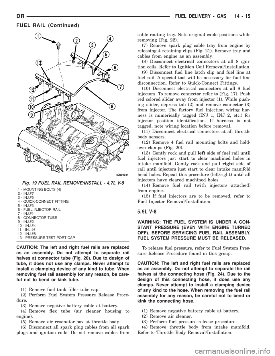
CAUTION: The left and right fuel rails are replaced
as an assembly. Do not attempt to separate rail
halves at connector tube (Fig. 20). Due to design of
tube, it does not use any clamps. Never attempt to
install a clamping device of any kind to tube. When
removing fuel rail assembly for any reason, be care-
ful not to bend or kink tube.
(1) Remove fuel tank filler tube cap.
(2) Perform Fuel System Pressure Release Proce-
dure.
(3) Remove negative battery cable at battery.
(4) Remove flex tube (air cleaner housing to
engine).
(5) Remove air resonator box at throttle body.
(6) Disconnect all spark plug cables from all spark
plugs and ignition coils. Do not remove cables fromcable routing tray. Note original cable positions while
removing (Fig. 22).
(7) Remove spark plug cable tray from engine by
releasing 4 retaining clips (Fig. 21). Remove tray and
cables from engine as an assembly.
(8) Disconnect electrical connectors at all 8 igni-
tion coils. Refer to Ignition Coil Removal/Installation.
(9) Disconnect fuel line latch clip and fuel line at
fuel rail. A special tool will be necessary for fuel line
disconnection. Refer to Quick-Connect Fittings.
(10) Disconnect electrical connectors at all 8 fuel
injectors. To remove connector refer to (Fig. 17). Push
red colored slider away from injector (1). While push-
ing slider, depress tab (2) and remove connector (3)
from injector. The factory fuel injection wiring har-
ness is numerically tagged (INJ 1, INJ 2, etc.) for
injector position identification. If harness is not
tagged, note wiring location before removal.
(11) Disconnect electrical connectors at all throttle
body sensors.
(12) Remove 4 fuel rail mounting bolts and hold-
own clamps (Fig. 20).
(13) Gently rock and pullleftside of fuel rail until
fuel injectors just start to clear machined holes in
intake manifold. Gently rock and pullrightside of
rail until injectors just start to clear intake manifold
head holes. Repeat this procedure (left/right) until all
injectors have cleared machined holes.
(14) Remove fuel rail (with injectors attached)
from engine.
(15) If fuel injectors are to be removed, refer to
Fuel Injector Removal/Installation.
5.9L V-8
WARNING: THE FUEL SYSTEM IS UNDER A CON-
STANT PRESSURE (EVEN WITH ENGINE TURNED
OFF). BEFORE SERVICING FUEL RAIL ASSEMBLY,
FUEL SYSTEM PRESSURE MUST BE RELEASED.
To release fuel pressure, refer to Fuel System Pres-
sure Release Procedure found in this group.
CAUTION: The left and right fuel rails are replaced
as an assembly. Do not attempt to separate the rail
halves at the connecting hose (Fig. 24). Due to the
design of this connecting hose, it does use any
clamps. Never attempt to install a clamping device
of any kind to the hose. When removing the fuel rail
assembly for any reason, be careful not to bend or
kink the connecting hose.
(1) Remove negative battery cable at battery.
(2) Remove air cleaner.
(3) Perform fuel pressure release procedure.
(4) Remove throttle body from intake manifold.
Refer to Throttle Body Removal/Installation.
Fig. 19 FUEL RAIL REMOVE/INSTALL - 4.7L V-8
1 - MOUNTING BOLTS (4)
2 - INJ.#7
3 - INJ.#5
4 - QUICK-CONNECT FITTING
5 - INJ.#3
6 - FUEL INJECTOR RAIL
7 - INJ.#1
8 - CONNECTOR TUBE
9 - INJ.#2
10 - INJ.#4
11 - INJ.#6
12 - INJ.#8
13 - PRESSURE TEST PORT CAP
DRFUEL DELIVERY - GAS 14 - 15
FUEL RAIL (Continued)