Actuator DODGE RAM 2003 Service Workshop Manual
[x] Cancel search | Manufacturer: DODGE, Model Year: 2003, Model line: RAM, Model: DODGE RAM 2003Pages: 2895, PDF Size: 83.15 MB
Page 1162 of 2895
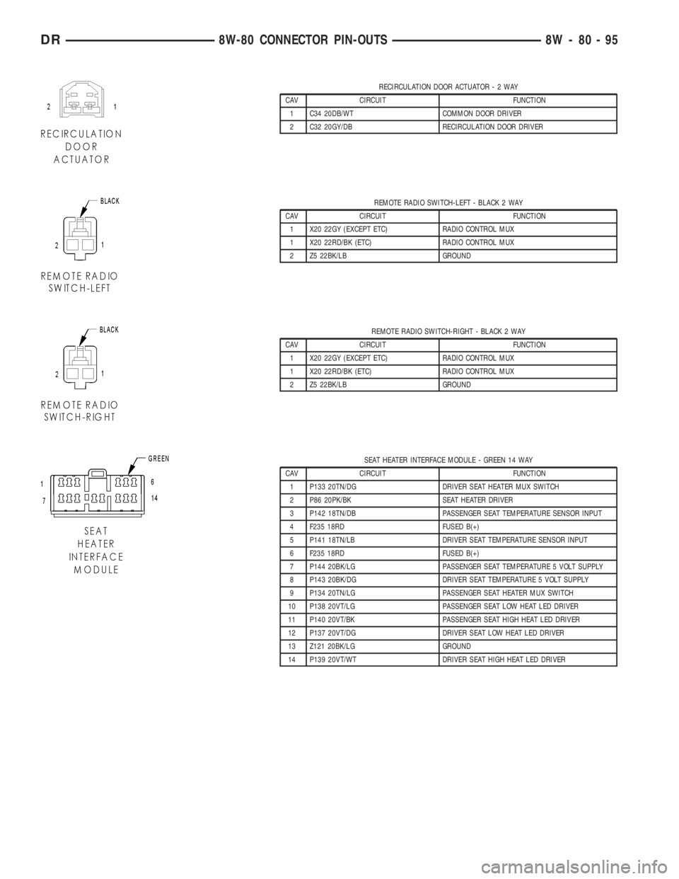
RECIRCULATION DOOR ACTUATOR-2WAY
CAV CIRCUIT FUNCTION
1 C34 20DB/WT COMMON DOOR DRIVER
2 C32 20GY/DB RECIRCULATION DOOR DRIVER
REMOTE RADIO SWITCH-LEFT - BLACK 2 WAY
CAV CIRCUIT FUNCTION
1 X20 22GY (EXCEPT ETC) RADIO CONTROL MUX
1 X20 22RD/BK (ETC) RADIO CONTROL MUX
2 Z5 22BK/LB GROUND
REMOTE RADIO SWITCH-RIGHT - BLACK 2 WAY
CAV CIRCUIT FUNCTION
1 X20 22GY (EXCEPT ETC) RADIO CONTROL MUX
1 X20 22RD/BK (ETC) RADIO CONTROL MUX
2 Z5 22BK/LB GROUND
SEAT HEATER INTERFACE MODULE - GREEN 14 WAY
CAV CIRCUIT FUNCTION
1 P133 20TN/DG DRIVER SEAT HEATER MUX SWITCH
2 P86 20PK/BK SEAT HEATER DRIVER
3 P142 18TN/DB PASSENGER SEAT TEMPERATURE SENSOR INPUT
4 F235 18RD FUSED B(+)
5 P141 18TN/LB DRIVER SEAT TEMPERATURE SENSOR INPUT
6 F235 18RD FUSED B(+)
7 P144 20BK/LG PASSENGER SEAT TEMPERATURE 5 VOLT SUPPLY
8 P143 20BK/DG DRIVER SEAT TEMPERATURE 5 VOLT SUPPLY
9 P134 20TN/LG PASSENGER SEAT HEATER MUX SWITCH
10 P138 20VT/LG PASSENGER SEAT LOW HEAT LED DRIVER
11 P140 20VT/BK PASSENGER SEAT HIGH HEAT LED DRIVER
12 P137 20VT/DG DRIVER SEAT LOW HEAT LED DRIVER
13 Z121 20BK/LG GROUND
14 P139 20VT/WT DRIVER SEAT HIGH HEAT LED DRIVER
DR8W-80 CONNECTOR PIN-OUTS 8W - 80 - 95
Page 1178 of 2895
8W-91 CONNECTOR/GROUND/SPLICE LOCATION
TABLE OF CONTENTS
page
CONNECTOR/GROUND/SPLICE LOCATION
DESCRIPTION..........................1
CONNECTOR/GROUND/SPLICE
LOCATION
DESCRIPTION
This section provides illustrations identifying con-
nector, ground, and splice locations in the vehicle.
Connector, ground, and splice indexes are provided.Use the wiring diagrams in each section for connec-
tor, ground, and splice identification. Refer to the
index for the proper figure number. For items that
are not shown in this section N/S is placed in the
Fig. column.
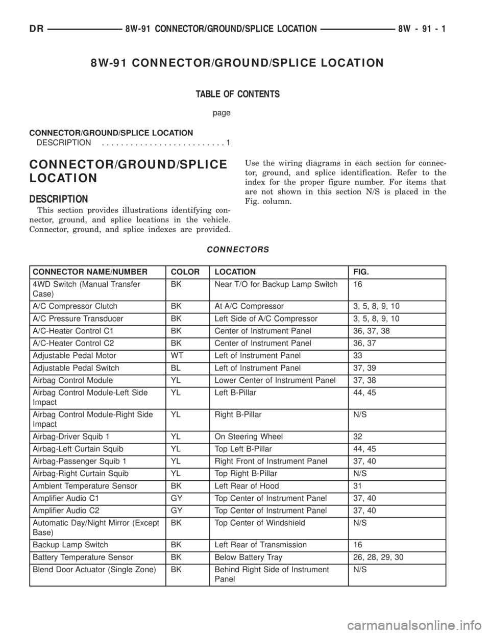
CONNECTORS
CONNECTOR NAME/NUMBER COLOR LOCATION FIG.
4WD Switch (Manual Transfer
Case)BK Near T/O for Backup Lamp Switch 16
A/C Compressor Clutch BK At A/C Compressor 3, 5, 8, 9, 10
A/C Pressure Transducer BK Left Side of A/C Compressor 3, 5, 8, 9, 10
A/C-Heater Control C1 BK Center of Instrument Panel 36, 37, 38
A/C-Heater Control C2 BK Center of Instrument Panel 36, 37
Adjustable Pedal Motor WT Left of Instrument Panel 33
Adjustable Pedal Switch BL Left of Instrument Panel 37, 39
Airbag Control Module YL Lower Center of Instrument Panel 37, 38
Airbag Control Module-Left Side
ImpactYL Left B-Pillar 44, 45
Airbag Control Module-Right Side
ImpactYL Right B-Pillar N/S
Airbag-Driver Squib 1 YL On Steering Wheel 32
Airbag-Left Curtain Squib YL Top Left B-Pillar 44, 45
Airbag-Passenger Squib 1 YL Right Front of Instrument Panel 37, 40
Airbag-Right Curtain Squib YL Top Right B-Pillar N/S
Ambient Temperature Sensor BK Left Rear of Hood 31
Amplifier Audio C1 GY Top Center of Instrument Panel 37, 40
Amplifier Audio C2 GY Top Center of Instrument Panel 37, 40
Automatic Day/Night Mirror (Except
Base)BK Top Center of Windshield N/S
Backup Lamp Switch BK Left Rear of Transmission 16
Battery Temperature Sensor BK Below Battery Tray 26, 28, 29, 30
Blend Door Actuator (Single Zone) BK Behind Right Side of Instrument
PanelN/S
DR8W-91 CONNECTOR/GROUND/SPLICE LOCATION 8W - 91 - 1
Page 1181 of 2895
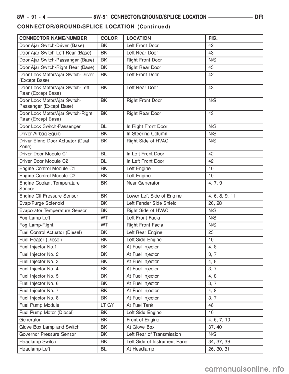
CONNECTOR NAME/NUMBER COLOR LOCATION FIG.
Door Ajar Switch-Driver (Base) BK Left Front Door 42
Door Ajar Switch-Left Rear (Base) BK Left Rear Door 43
Door Ajar Switch-Passenger (Base) BK Right Front Door N/S
Door Ajar Switch-Right Rear (Base) BK Right Rear Door 43
Door Lock Motor/Ajar Switch-Driver
(Except Base)BK Left Front Door 42
Door Lock Motor/Ajar Switch-Left
Rear (Except Base)BK Left Rear Door 43
Door Lock Motor/Ajar Switch-
Passenger (Except Base)BK Right Front Door N/S
Door Lock Motor/Ajar Switch-Right
Rear (Except Base)BK Right Rear Door 43
Door Lock Switch-Passenger BL In Right Front Door N/S
Driver Airbag Squib BK In Steering Column N/S
Driver Blend Door Actuator (Dual
Zone)BK Right Side of HVAC N/S
Driver Door Module C1 BL In Left Front Door 42
Driver Door Module C2 BL In Left Front Door 42
Engine Control Module C1 BK Left Engine 10
Engine Control Module C2 BK Left Engine 10
Engine Coolant Temperature
SensorBK Near Generator 4, 7, 9
Engine Oil Pressure Sensor BK Lower Left Side of Engine 4, 6, 8, 9, 11
Evap/Purge Solenoid BK Left Fender Side Shield 26, 28
Evaporator Temperature Sensor BK Right Side of HVAC N/S
Fog Lamp-Left WT Left Front Facia N/S
Fog Lamp-Right WT Right Front Facia N/S
Fuel Control Actuator (Diesel) BK Left Rear Engine 23
Fuel Heater (Diesel) BK Left Side Engine 10
Fuel Injector No.1 BK At Fuel Injector 4, 8
Fuel Injector No. 2 BK At Fuel Injector 3, 7
Fuel Injector No. 3 BK At Fuel Injector 4, 8
Fuel Injector No. 4 BK At Fuel Injector 3, 7
Fuel Injector No. 5 BK At Fuel Injector 4, 8
Fuel Injector No. 6 BK At Fuel Injector 3, 7
Fuel Injector No. 7 BK At Fuel Injector 4, 8
Fuel Injector No. 8 BK At Fuel Injector 3, 7
Fuel Pump Module LT GY At Fuel Tank 48
Fuel Pump Motor (Diesel) BK Left Side Engine 10
Generator BK Front of Engine 4, 6, 7, 10
Glove Box Lamp and Switch BK At Glove Box 37, 40
Governor Pressure Sensor BK Left Rear of Transmission N/S
Headlamp Switch BK Left Side of Instrument Panel 34, 37, 39
Headlamp-Left BL At Headlamp 26, 30, 31
8W - 91 - 4 8W-91 CONNECTOR/GROUND/SPLICE LOCATIONDR
CONNECTOR/GROUND/SPLICE LOCATION (Continued)
Page 1183 of 2895
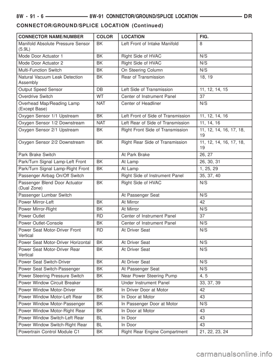
CONNECTOR NAME/NUMBER COLOR LOCATION FIG.
Manifold Absolute Pressure Sensor
(5.9L)BK Left Front of Intake Manifold 8
Mode Door Actuator 1 BK Right Side of HVAC N/S
Mode Door Actuator 2 BK Right Side of HVAC N/S
Multi-Function Switch BK On Steering Column N/S
Natural Vacuum Leak Detection
AssemblyBK Rear of Transmission 18, 19
Output Speed Sensor DB Left Side of Transmission 11, 12, 14, 15
Overdrive Switch WT Center of Instrument Panel 37
Overhead Map/Reading Lamp
(Except Base)NAT Center of Headliner N/S
Oxygen Sensor 1/1 Upstream BK Left Front of Side of Transmission 11, 12, 14, 16
Oxygen Sensor 1/2 Downstream NAT Left Rear of Side of Transmission 11, 14, 16
Oxygen Sensor 2/1 Upstream BK Right Front Side of Transmission 11, 12, 14, 16, 17, 18,
19
Oxygen Sensor 2/2 Downstream BK Right Rear Side of Transmission 11, 12, 14, 16, 17, 18,
19
Park Brake Switch At Park Brake 26, 27
Park/Turn Signal Lamp-Left Front BK At Lamp 26, 30, 31
Park/Turn Signal Lamp-Right Front BK At Lamp 1, 25, 29
Passenger Airbag On/Off Switch Right Side of Instrument Panel 35, 37, 40
Passenger Blend Door Actuator
(Dual Zone)BK Right Side of HVAC N/S
Passenger Lumbar Switch At Passenger Seat N/S
Power Mirror-Left BK At Mirror 42
Power Mirror-Right BK At Mirror N/S
Power Outlet RD Center of Instrument Panel 37
Power Outlet-Console BK Center of Instrument Panel N/S
Power Seat Motor-Driver Front
VerticalRD At Driver Seat N/S
Power Seat Motor-Driver Horizontal BK At Driver Seat N/S
Power Seat Motor-Driver Rear
VerticalBK At Driver Seat N/S
Power Seat Switch-Driver BK At Driver Seat N/S
Power Seat Switch-Passenger BK At Passenger Seat N/S
Power Steering Pressure Switch BK Near Power Steering Pump 4, 5
Power Window Circuit Breaker Under Instrument Panel 33, 37, 39
Power Window Motor-Driver BK In Driver Door at Motor 42
Power Window Motor-Left Rear BK In Door at Motor 43
Power Window Motor-Passenger BK In Passenger Door at Motor N/S
Power Window Motor-Right Rear BK In Door at Motor 43
Power Window Switch-Left Rear BL In Door 43
Power Window Switch-Right Rear BL In Door 43
Powertrain Control Module C1 BK Right Rear Engine Compartment 21, 22, 23, 24
8W - 91 - 6 8W-91 CONNECTOR/GROUND/SPLICE LOCATIONDR
CONNECTOR/GROUND/SPLICE LOCATION (Continued)
Page 1184 of 2895
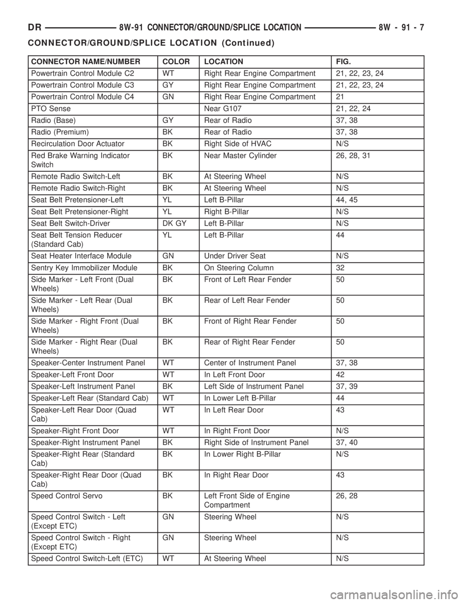
CONNECTOR NAME/NUMBER COLOR LOCATION FIG.
Powertrain Control Module C2 WT Right Rear Engine Compartment 21, 22, 23, 24
Powertrain Control Module C3 GY Right Rear Engine Compartment 21, 22, 23, 24
Powertrain Control Module C4 GN Right Rear Engine Compartment 21
PTO Sense Near G107 21, 22, 24
Radio (Base) GY Rear of Radio 37, 38
Radio (Premium) BK Rear of Radio 37, 38
Recirculation Door Actuator BK Right Side of HVAC N/S
Red Brake Warning Indicator
SwitchBK Near Master Cylinder 26, 28, 31
Remote Radio Switch-Left BK At Steering Wheel N/S
Remote Radio Switch-Right BK At Steering Wheel N/S
Seat Belt Pretensioner-Left YL Left B-Pillar 44, 45
Seat Belt Pretensioner-Right YL Right B-Pillar N/S
Seat Belt Switch-Driver DK GY Left B-Pillar N/S
Seat Belt Tension Reducer
(Standard Cab)YL Left B-Pillar 44
Seat Heater Interface Module GN Under Driver Seat N/S
Sentry Key Immobilizer Module BK On Steering Column 32
Side Marker - Left Front (Dual
Wheels)BK Front of Left Rear Fender 50
Side Marker - Left Rear (Dual
Wheels)BK Rear of Left Rear Fender 50
Side Marker - Right Front (Dual
Wheels)BK Front of Right Rear Fender 50
Side Marker - Right Rear (Dual
Wheels)BK Rear of Right Rear Fender 50
Speaker-Center Instrument Panel WT Center of Instrument Panel 37, 38
Speaker-Left Front Door WT In Left Front Door 42
Speaker-Left Instrument Panel BK Left Side of Instrument Panel 37, 39
Speaker-Left Rear (Standard Cab) WT In Lower Left B-Pillar 44
Speaker-Left Rear Door (Quad
Cab)WT In Left Rear Door 43
Speaker-Right Front Door WT In Right Front Door N/S
Speaker-Right Instrument Panel BK Right Side of Instrument Panel 37, 40
Speaker-Right Rear (Standard
Cab)BK In Lower Right B-Pillar N/S
Speaker-Right Rear Door (Quad
Cab)BK In Right Rear Door 43
Speed Control Servo BK Left Front Side of Engine
Compartment26, 28
Speed Control Switch - Left
(Except ETC)GN Steering Wheel N/S
Speed Control Switch - Right
(Except ETC)GN Steering Wheel N/S
Speed Control Switch-Left (ETC) WT At Steering Wheel N/S
DR8W-91 CONNECTOR/GROUND/SPLICE LOCATION 8W - 91 - 7
CONNECTOR/GROUND/SPLICE LOCATION (Continued)
Page 1187 of 2895
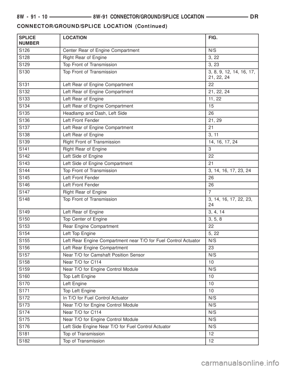
SPLICE
NUMBERLOCATION FIG.
S126 Center Rear of Engine Compartment N/S
S128 Right Rear of Engine 3, 22
S129 Top Front of Transmission 3, 23
S130 Top Front of Transmission 3, 8, 9, 12, 14, 16, 17,
21, 22, 24
S131 Left Rear of Engine Compartment 22
S132 Left Rear of Engine Compartment 21, 22, 24
S133 Left Rear of Engine 11, 22
S134 Left Rear of Engine Compartment 15
S135 Headlamp and Dash, Left Side 26
S136 Left Front Fender 21, 29
S137 Left Rear of Engine Compartment 21
S138 Left Rear of Engine 3, 11
S139 Right Front of Transmission 14, 16, 17, 24
S141 Right Rear of Engine 3
S142 Left Side of Engine 22
S143 Left Side of Engine Compartment 21
S144 Top Front of Transmission 3, 14, 16, 17, 23, 24
S145 Left Front Fender 26
S146 Left Front Fender 26
S147 Right Rear of Engine 7
S148 Top Front of Transmission 3, 14, 16, 17, 22, 23,
24
S149 Left Rear of Engine 3, 4, 14
S150 Top Center of Engine 3, 5, 8
S153 Rear Engine Compartment 22
S154 Left Top Engine 5, 22
S155 Left Rear Engine Compartment near T/O for Fuel Control Actuator N/S
S156 Left Rear Engine Compartment 23
S157 Near T/O for Camshaft Position Sensor N/S
S158 Near T/O for C114 10
S159 Near T/O for Engine Control Module N/S
S160 Top Left Engine 10
S170 Left Engine 10
S171 Top Left Engine 10
S172 In T/O for Fuel Control Actuator N/S
S173 Near T/O for Engine Control Module N/S
S174 Near T/O for C114 N/S
S175 Near T/O for Engine Control Module N/S
S176 Left Side Engine Near T/O for Fuel Control Actuator N/S
S181 Top of Transmission 12
S182 Top of Transmission 12
8W - 91 - 10 8W-91 CONNECTOR/GROUND/SPLICE LOCATIONDR
CONNECTOR/GROUND/SPLICE LOCATION (Continued)
Page 1667 of 2895
²Improved operating economy
²Altitude compensation
²Noise reduction.
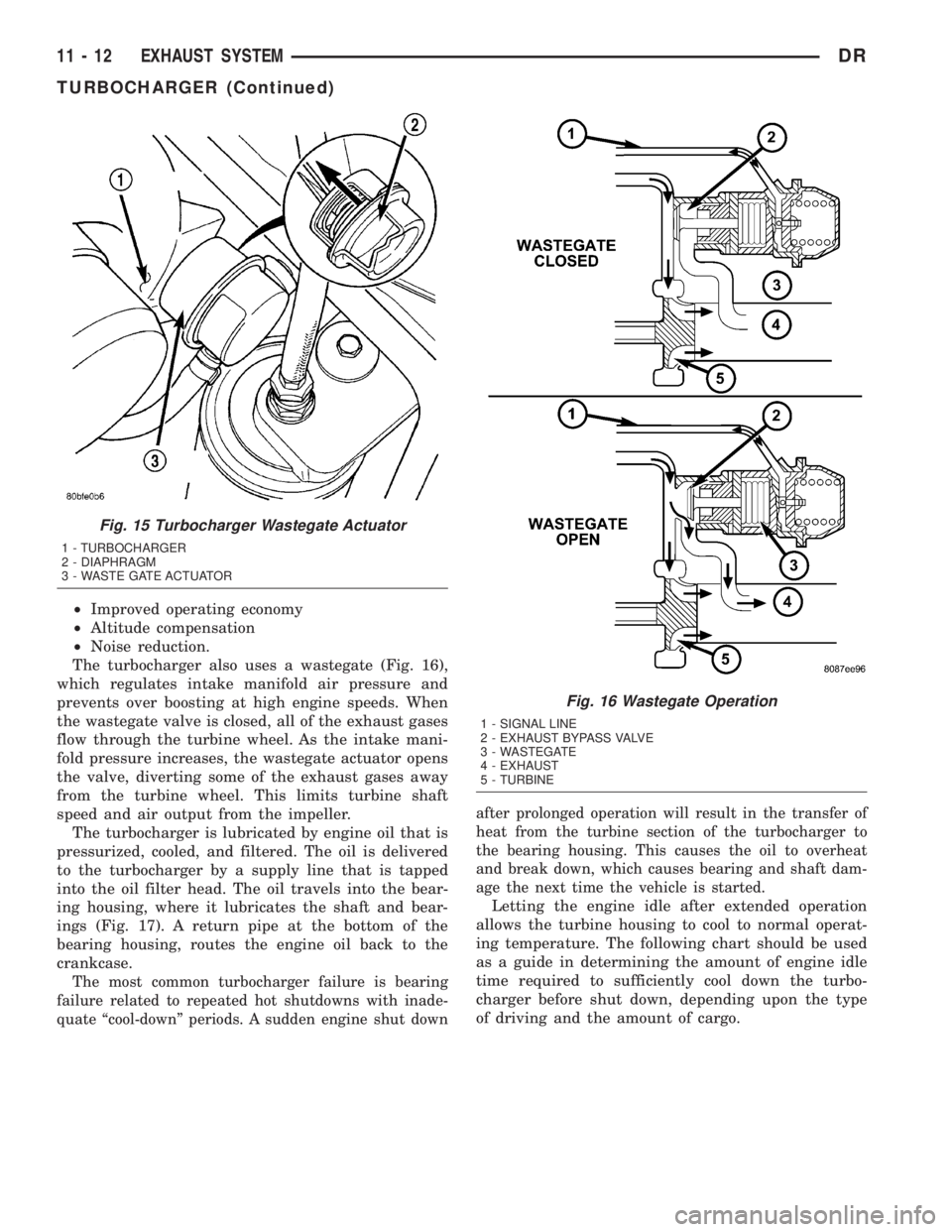
The turbocharger also uses a wastegate (Fig. 16),
which regulates intake manifold air pressure and
prevents over boosting at high engine speeds. When
the wastegate valve is closed, all of the exhaust gases
flow through the turbine wheel. As the intake mani-
fold pressure increases, the wastegate actuator opens
the valve, diverting some of the exhaust gases away
from the turbine wheel. This limits turbine shaft
speed and air output from the impeller.
The turbocharger is lubricated by engine oil that is
pressurized, cooled, and filtered. The oil is delivered
to the turbocharger by a supply line that is tapped
into the oil filter head. The oil travels into the bear-
ing housing, where it lubricates the shaft and bear-
ings (Fig. 17). A return pipe at the bottom of the
bearing housing, routes the engine oil back to the
crankcase.
The most common turbocharger failure is bearing
failure related to repeated hot shutdowns with inade-
quate ªcool-downº periods. A sudden engine shut downafter prolonged operation will result in the transfer of
heat from the turbine section of the turbocharger to
the bearing housing. This causes the oil to overheat
and break down, which causes bearing and shaft dam-
age the next time the vehicle is started.
Letting the engine idle after extended operation
allows the turbine housing to cool to normal operat-
ing temperature. The following chart should be used
as a guide in determining the amount of engine idle
time required to sufficiently cool down the turbo-
charger before shut down, depending upon the type
of driving and the amount of cargo.
Fig. 15 Turbocharger Wastegate Actuator
1 - TURBOCHARGER
2 - DIAPHRAGM
3 - WASTE GATE ACTUATOR
Fig. 16 Wastegate Operation
1 - SIGNAL LINE
2 - EXHAUST BYPASS VALVE
3 - WASTEGATE
4 - EXHAUST
5 - TURBINE
11 - 12 EXHAUST SYSTEMDR
TURBOCHARGER (Continued)
Page 1754 of 2895
FUEL DELIVERY - DIESEL
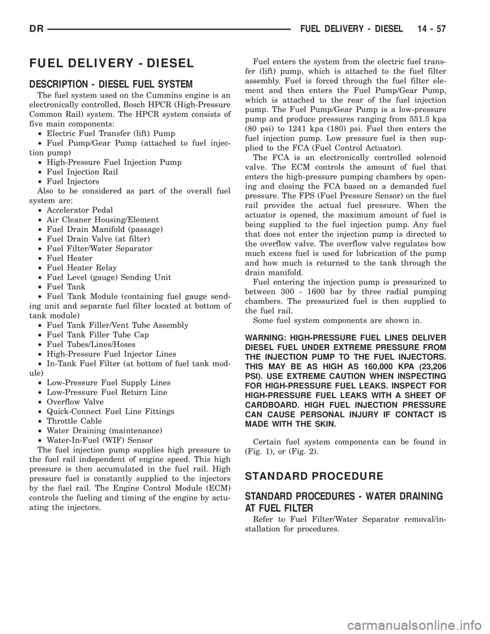
DESCRIPTION - DIESEL FUEL SYSTEM
The fuel system used on the Cummins engine is an
electronically controlled, Bosch HPCR (High-Pressure
Common Rail) system. The HPCR system consists of
five main components:
²Electric Fuel Transfer (lift) Pump
²Fuel Pump/Gear Pump (attached to fuel injec-
tion pump)
²High-Pressure Fuel Injection Pump
²Fuel Injection Rail
²Fuel Injectors
Also to be considered as part of the overall fuel
system are:
²Accelerator Pedal
²Air Cleaner Housing/Element
²Fuel Drain Manifold (passage)
²Fuel Drain Valve (at filter)
²Fuel Filter/Water Separator
²Fuel Heater
²Fuel Heater Relay
²Fuel Level (gauge) Sending Unit
²Fuel Tank
²Fuel Tank Module (containing fuel gauge send-
ing unit and separate fuel filter located at bottom of
tank module)
²Fuel Tank Filler/Vent Tube Assembly
²Fuel Tank Filler Tube Cap
²Fuel Tubes/Lines/Hoses
²High-Pressure Fuel Injector Lines
²In-Tank Fuel Filter (at bottom of fuel tank mod-
ule)
²Low-Pressure Fuel Supply Lines
²Low-Pressure Fuel Return Line
²Overflow Valve
²Quick-Connect Fuel Line Fittings
²Throttle Cable
²Water Draining (maintenance)
²Water-In-Fuel (WIF) Sensor
The fuel injection pump supplies high pressure to
the fuel rail independent of engine speed. This high
pressure is then accumulated in the fuel rail. High
pressure fuel is constantly supplied to the injectors
by the fuel rail. The Engine Control Module (ECM)
controls the fueling and timing of the engine by actu-
ating the injectors.Fuel enters the system from the electric fuel trans-
fer (lift) pump, which is attached to the fuel filter
assembly. Fuel is forced through the fuel filter ele-
ment and then enters the Fuel Pump/Gear Pump,
which is attached to the rear of the fuel injection
pump. The Fuel Pump/Gear Pump is a low-pressure
pump and produce pressures ranging from 551.5 kpa
(80 psi) to 1241 kpa (180) psi. Fuel then enters the
fuel injection pump. Low pressure fuel is then sup-
plied to the FCA (Fuel Control Actuator).
The FCA is an electronically controlled solenoid
valve. The ECM controls the amount of fuel that
enters the high-pressure pumping chambers by open-
ing and closing the FCA based on a demanded fuel
pressure. The FPS (Fuel Pressure Sensor) on the fuel
rail provides the actual fuel pressure. When the
actuator is opened, the maximum amount of fuel is
being supplied to the fuel injection pump. Any fuel
that does not enter the injection pump is directed to
the overflow valve. The overflow valve regulates how
much excess fuel is used for lubrication of the pump
and how much is returned to the tank through the
drain manifold.
Fuel entering the injection pump is pressurized to
between 300 - 1600 bar by three radial pumping
chambers. The pressurized fuel is then supplied to
the fuel rail.
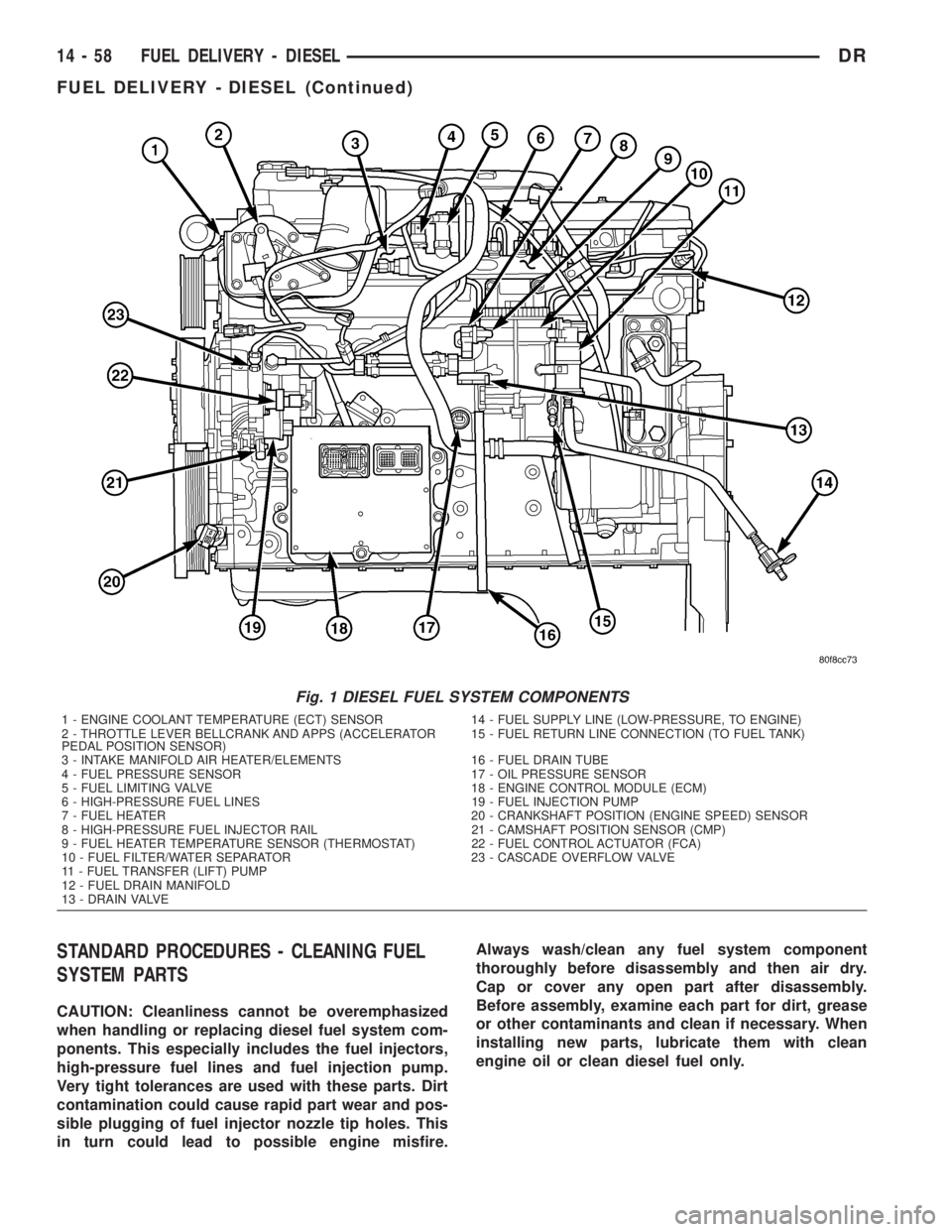
Some fuel system components are shown in.
WARNING: HIGH-PRESSURE FUEL LINES DELIVER
DIESEL FUEL UNDER EXTREME PRESSURE FROM
THE INJECTION PUMP TO THE FUEL INJECTORS.
THIS MAY BE AS HIGH AS 160,000 KPA (23,206
PSI). USE EXTREME CAUTION WHEN INSPECTING
FOR HIGH-PRESSURE FUEL LEAKS. INSPECT FOR
HIGH-PRESSURE FUEL LEAKS WITH A SHEET OF
CARDBOARD. HIGH FUEL INJECTION PRESSURE
CAN CAUSE PERSONAL INJURY IF CONTACT IS
MADE WITH THE SKIN.
Certain fuel system components can be found in
(Fig. 1), or (Fig. 2).
STANDARD PROCEDURE
STANDARD PROCEDURES - WATER DRAINING
AT FUEL FILTER
Refer to Fuel Filter/Water Separator removal/in-
stallation for procedures.
DRFUEL DELIVERY - DIESEL 14 - 57
Page 1755 of 2895
STANDARD PROCEDURES - CLEANING FUEL
SYSTEM PARTS
CAUTION: Cleanliness cannot be overemphasized
when handling or replacing diesel fuel system com-
ponents. This especially includes the fuel injectors,
high-pressure fuel lines and fuel injection pump.
Very tight tolerances are used with these parts. Dirt
contamination could cause rapid part wear and pos-
sible plugging of fuel injector nozzle tip holes. This
in turn could lead to possible engine misfire.Always wash/clean any fuel system component
thoroughly before disassembly and then air dry.
Cap or cover any open part after disassembly.
Before assembly, examine each part for dirt, grease
or other contaminants and clean if necessary. When
installing new parts, lubricate them with clean
engine oil or clean diesel fuel only.
Fig. 1 DIESEL FUEL SYSTEM COMPONENTS
1 - ENGINE COOLANT TEMPERATURE (ECT) SENSOR 14 - FUEL SUPPLY LINE (LOW-PRESSURE, TO ENGINE)
2 - THROTTLE LEVER BELLCRANK AND APPS (ACCELERATOR
PEDAL POSITION SENSOR)15 - FUEL RETURN LINE CONNECTION (TO FUEL TANK)
3 - INTAKE MANIFOLD AIR HEATER/ELEMENTS 16 - FUEL DRAIN TUBE
4 - FUEL PRESSURE SENSOR 17 - OIL PRESSURE SENSOR
5 - FUEL LIMITING VALVE 18 - ENGINE CONTROL MODULE (ECM)
6 - HIGH-PRESSURE FUEL LINES 19 - FUEL INJECTION PUMP
7 - FUEL HEATER 20 - CRANKSHAFT POSITION (ENGINE SPEED) SENSOR
8 - HIGH-PRESSURE FUEL INJECTOR RAIL 21 - CAMSHAFT POSITION SENSOR (CMP)
9 - FUEL HEATER TEMPERATURE SENSOR (THERMOSTAT) 22 - FUEL CONTROL ACTUATOR (FCA)
10 - FUEL FILTER/WATER SEPARATOR 23 - CASCADE OVERFLOW VALVE
11 - FUEL TRANSFER (LIFT) PUMP
12 - FUEL DRAIN MANIFOLD
13 - DRAIN VALVE
14 - 58 FUEL DELIVERY - DIESELDR
FUEL DELIVERY - DIESEL (Continued)
Page 1762 of 2895
pump. The Fuel Pump/Gear Pump is a low-pressure
pump and produce pressures ranging from 551.5 kpa
(80 psi) to 1241 kpa (180) psi. Fuel then enters the
fuel injection pump. Low pressure fuel is then sup-
plied to the FAC (Fuel Control Actuator).
The FAC is an electronically controlled solenoid
valve. The ECM controls the amount of fuel that
enters the high-pressure pumping chambers by open-
ing and closing the FAC based on a demanded fuel
pressure. The FPS (Fuel Pressure Sensor) on the fuel
rail provides the actual fuel pressure. When the
actuator is opened, the maximum amount of fuel is
being supplied to the fuel injection pump. Any fuel
that does not enter the injection pump is directed to
the overflow valve. The overflow valve regulates how
much excess fuel is used for lubrication of the pump
and how much is returned to the tank through the
drain manifold.
Fuel entering the injection pump is pressurized to
between 300 - 1600 bar by three radial pumping
chambers. The pressurized fuel is then supplied to
the fuel rail.
DIAGNOSIS AND TESTING - FUEL INJECTION
PUMP TIMING
With the Bosch injection pump, there are no
mechanical adjustments needed or necessary to
accomplish fuel injection timing. All timing and fuel
adjustments are electrically made by the engine
mounted Engine Control Module (ECM).
REMOVAL
CAUTION: Cleanliness cannot be overemphasized
when handling or replacing diesel fuel system com-
ponents. This especially includes the fuel injectors,
high-pressure fuel lines and fuel injection pump.
Very tight tolerances are used with these parts. Dirt
contamination could cause rapid part wear and pos-
sible plugging of fuel injector nozzle tip holes. This
in turn could lead to possible engine misfire.
Always wash/clean any fuel system component
thoroughly before disassembly and then air dry.
Cap or cover any open part after disassembly.
Before assembly, examine each part for dirt, grease
or other contaminants and clean if necessary. When
installing new parts, lubricate them with clean
engine oil or clean diesel fuel only.
(1) Disconnect both negative battery cables at both
batteries. Cover and isolate ends of both cables.
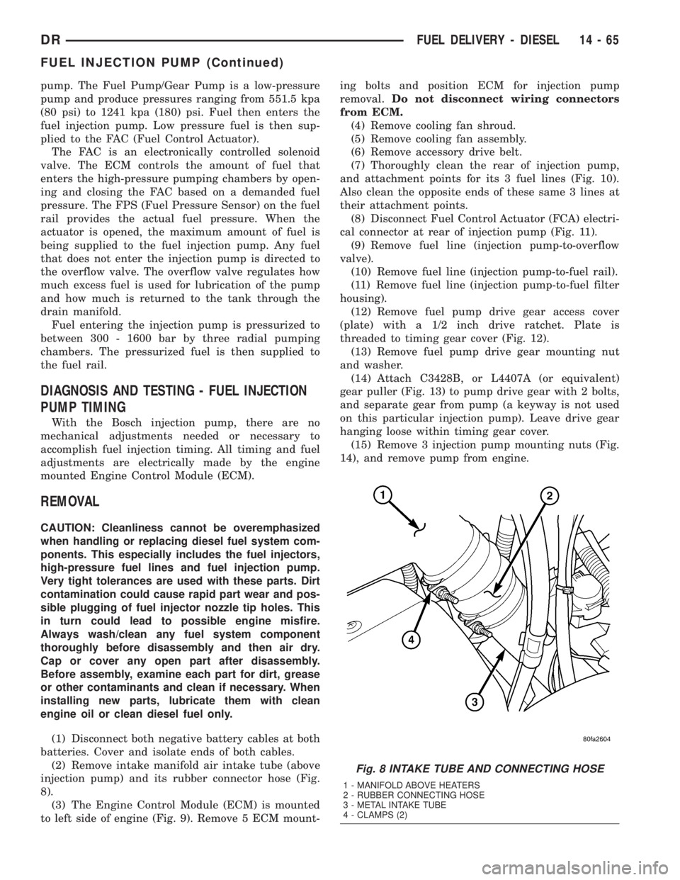
(2) Remove intake manifold air intake tube (above
injection pump) and its rubber connector hose (Fig.
8).
(3) The Engine Control Module (ECM) is mounted
to left side of engine (Fig. 9). Remove 5 ECM mount-ing bolts and position ECM for injection pump
removal.Do not disconnect wiring connectors
from ECM.
(4) Remove cooling fan shroud.
(5) Remove cooling fan assembly.
(6) Remove accessory drive belt.
(7) Thoroughly clean the rear of injection pump,
and attachment points for its 3 fuel lines (Fig. 10).
Also clean the opposite ends of these same 3 lines at
their attachment points.
(8) Disconnect Fuel Control Actuator (FCA) electri-
cal connector at rear of injection pump (Fig. 11).
(9) Remove fuel line (injection pump-to-overflow
valve).
(10) Remove fuel line (injection pump-to-fuel rail).
(11) Remove fuel line (injection pump-to-fuel filter
housing).
(12) Remove fuel pump drive gear access cover
(plate) with a 1/2 inch drive ratchet. Plate is
threaded to timing gear cover (Fig. 12).
(13) Remove fuel pump drive gear mounting nut
and washer.
(14) Attach C3428B, or L4407A (or equivalent)
gear puller (Fig. 13) to pump drive gear with 2 bolts,
and separate gear from pump (a keyway is not used
on this particular injection pump). Leave drive gear
hanging loose within timing gear cover.
(15) Remove 3 injection pump mounting nuts (Fig.
14), and remove pump from engine.
Fig. 8 INTAKE TUBE AND CONNECTING HOSE
1 - MANIFOLD ABOVE HEATERS
2 - RUBBER CONNECTING HOSE
3 - METAL INTAKE TUBE
4 - CLAMPS (2)
DRFUEL DELIVERY - DIESEL 14 - 65
FUEL INJECTION PUMP (Continued)