Actuator DODGE RAM 2003 Service Manual Online
[x] Cancel search | Manufacturer: DODGE, Model Year: 2003, Model line: RAM, Model: DODGE RAM 2003Pages: 2895, PDF Size: 83.15 MB
Page 2605 of 2895

DOOR GLASS
REMOVAL
(1) Remove the glass run channels. (Refer to 23 -
BODY/DOORS - REAR/GLASS RUN CHANNEL -
REMOVAL)
(2) Remove the glass support and place the glass
into the bottom of the door.
(3) Separate the glass run weatherstrip from the
rear of the window opening.
(4) Remove the inner belt molding. (Refer to 23 -
BODY/WEATHERSTRIP/SEALS/FRONT DOOR
INNER BELT WEATHERSTRIP - REMOVAL)
(5) Remove the glass from the window opening.
INSTALLATION
(1) Install the glass through the window opening
and pace the glass into the bottom of the door.
(2) Install the inner belt molding. (Refer to 23 -
BODY/WEATHERSTRIP/SEALS/FRONT DOOR
INNER BELT WEATHERSTRIP - INSTALLATION)
(3) Stuff the glass run weatherstrip into the win-
dow frame.
(4) Secure the glass in the up position using a
wood wedge or equivalent.
(5) Install the glass run channels. (Refer to 23 -
BODY/DOORS - REAR/GLASS RUN CHANNEL -
INSTALLATION)
EXTERIOR HANDLE
REMOVAL
(1) Remove the front glass run channel. (Refer to
23 - BODY/DOORS - REAR/GLASS RUN CHANNEL
- REMOVAL)
(2) Disconnect the latch actuator rod. (Fig. 2)
(3) Remove the nuts and remove the handle.
INSTALLATION
(1) Install the latch and install the nuts.
(2) Connect the latch actuator rod.
(3) Install the front glass run channel. (Refer to 23
- BODY/DOORS - REAR/GLASS RUN CHANNEL -
INSTALLATION)
GLASS RUN CHANNEL
REMOVAL
(1) Remove the window regulator. (Refer to 23 -
BODY/DOORS - REAR/WINDOW REGULATOR -
REMOVAL)
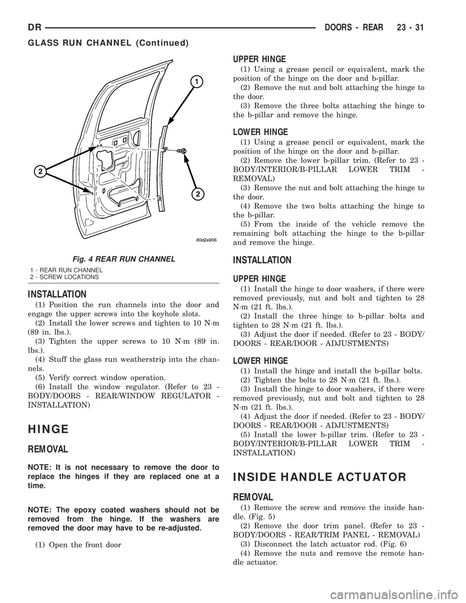
(2) Remove the bottom screws and loosen the top
screws from bolt channels. (Fig. 3) and (Fig. 4)(3) Slide the channels up to disengage from the
keyhole slots.
(4) Separate the glass run weatherstrip from the
channel and remove the channels.
Fig. 2 EXTERIOR HANDLE
1 - LATCH ACTUATOR ROD
2-LATCH
3 - NUTS (2)
Fig. 3 FRONT RUN CHANNEL
1 - BOLTS
2 - FRONT RUN CHANNEL
23 - 30 DOORS - REARDR
Page 2606 of 2895
INSTALLATION
(1) Position the run channels into the door and
engage the upper screws into the keyhole slots.
(2) Install the lower screws and tighten to 10 N´m
(89 in. lbs.).
(3) Tighten the upper screws to 10 N´m (89 in.
lbs.).
(4) Stuff the glass run weatherstrip into the chan-
nels.
(5) Verify correct window operation.
(6) Install the window regulator. (Refer to 23 -
BODY/DOORS - REAR/WINDOW REGULATOR -
INSTALLATION)
HINGE
REMOVAL
NOTE: It is not necessary to remove the door to
replace the hinges if they are replaced one at a
time.
NOTE: The epoxy coated washers should not be
removed from the hinge. If the washers are
removed the door may have to be re-adjusted.
(1) Open the front door
UPPER HINGE
(1) Using a grease pencil or equivalent, mark the
position of the hinge on the door and b-pillar.
(2) Remove the nut and bolt attaching the hinge to
the door.
(3) Remove the three bolts attaching the hinge to
the b-pillar and remove the hinge.
LOWER HINGE
(1) Using a grease pencil or equivalent, mark the
position of the hinge on the door and b-pillar.
(2) Remove the lower b-pillar trim. (Refer to 23 -
BODY/INTERIOR/B-PILLAR LOWER TRIM -
REMOVAL)
(3) Remove the nut and bolt attaching the hinge to
the door.
(4) Remove the two bolts attaching the hinge to
the b-pillar.
(5) From the inside of the vehicle remove the
remaining bolt attaching the hinge to the b-pillar
and remove the hinge.
INSTALLATION
UPPER HINGE
(1) Install the hinge to door washers, if there were
removed previously, nut and bolt and tighten to 28
N´m (21 ft. lbs.).
(2) Install the three hinge to b-pillar bolts and
tighten to 28 N´m (21 ft. lbs.).
(3) Adjust the door if needed. (Refer to 23 - BODY/
DOORS - REAR/DOOR - ADJUSTMENTS)
LOWER HINGE
(1) Install the hinge and install the b-pillar bolts.
(2) Tighten the bolts to 28 N´m (21 ft. lbs.).
(3) Install the hinge to door washers, if there were
removed previously, nut and bolt and tighten to 28
N´m (21 ft. lbs.).
(4) Adjust the door if needed. (Refer to 23 - BODY/
DOORS - REAR/DOOR - ADJUSTMENTS)
(5) Install the lower b-pillar trim. (Refer to 23 -
BODY/INTERIOR/B-PILLAR LOWER TRIM -
INSTALLATION)
INSIDE HANDLE ACTUATOR
REMOVAL
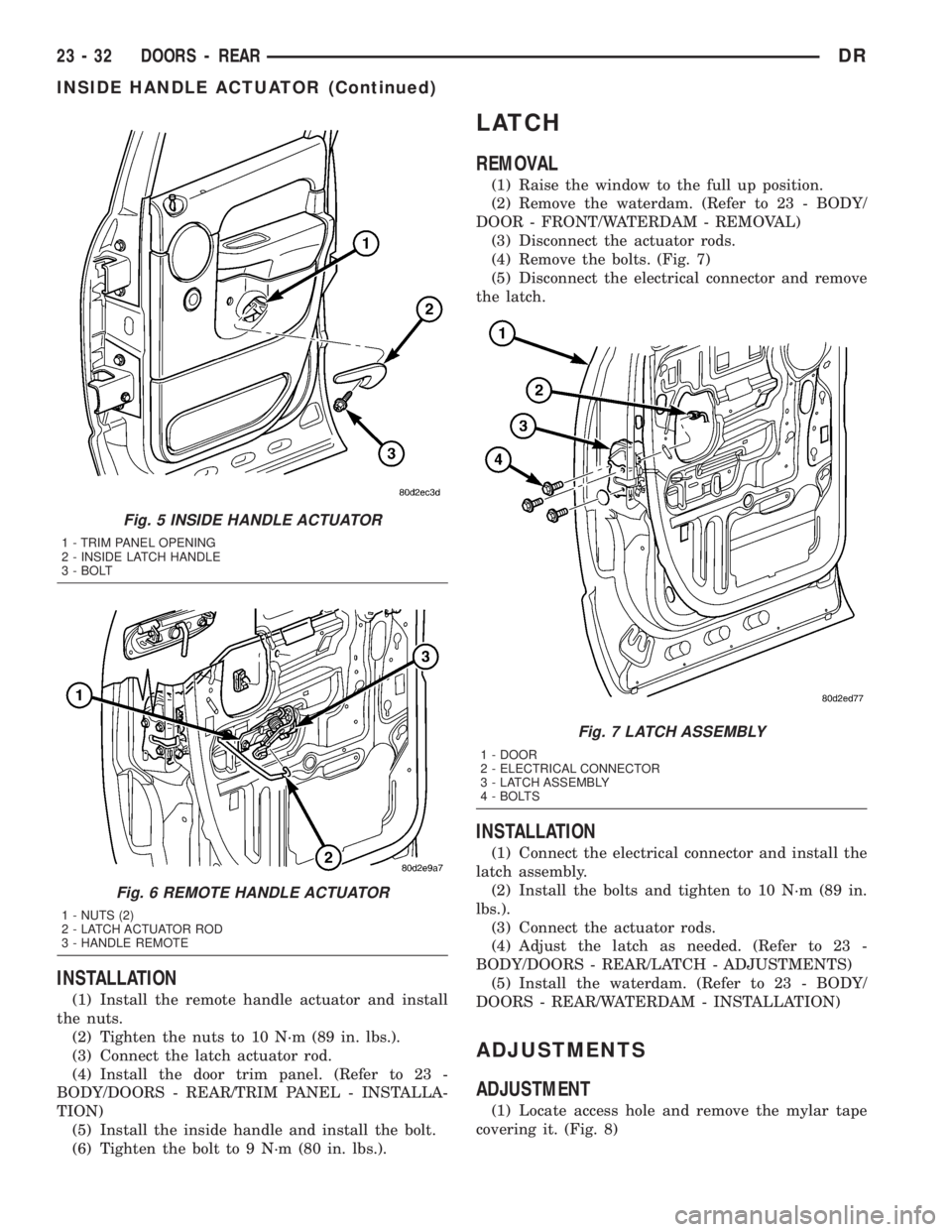
(1) Remove the screw and remove the inside han-
dle. (Fig. 5)
(2) Remove the door trim panel. (Refer to 23 -
BODY/DOORS - REAR/TRIM PANEL - REMOVAL)
(3) Disconnect the latch actuator rod. (Fig. 6)
(4) Remove the nuts and remove the remote han-
dle actuator.
Fig. 4 REAR RUN CHANNEL
1 - REAR RUN CHANNEL
2 - SCREW LOCATIONS
DRDOORS - REAR 23 - 31
GLASS RUN CHANNEL (Continued)
Page 2607 of 2895
INSTALLATION
(1) Install the remote handle actuator and install
the nuts.
(2) Tighten the nuts to 10 N´m (89 in. lbs.).
(3) Connect the latch actuator rod.
(4) Install the door trim panel. (Refer to 23 -
BODY/DOORS - REAR/TRIM PANEL - INSTALLA-
TION)
(5) Install the inside handle and install the bolt.
(6) Tighten the bolt to 9 N´m (80 in. lbs.).
LATCH
REMOVAL
(1) Raise the window to the full up position.
(2) Remove the waterdam. (Refer to 23 - BODY/
DOOR - FRONT/WATERDAM - REMOVAL)
(3) Disconnect the actuator rods.
(4) Remove the bolts. (Fig. 7)
(5) Disconnect the electrical connector and remove
the latch.
INSTALLATION
(1) Connect the electrical connector and install the
latch assembly.
(2) Install the bolts and tighten to 10 N´m (89 in.
lbs.).
(3) Connect the actuator rods.
(4) Adjust the latch as needed. (Refer to 23 -
BODY/DOORS - REAR/LATCH - ADJUSTMENTS)
(5) Install the waterdam. (Refer to 23 - BODY/
DOORS - REAR/WATERDAM - INSTALLATION)
ADJUSTMENTS
ADJUSTMENT
(1) Locate access hole and remove the mylar tape
covering it. (Fig. 8)
Fig. 5 INSIDE HANDLE ACTUATOR
1 - TRIM PANEL OPENING
2 - INSIDE LATCH HANDLE
3 - BOLT
Fig. 6 REMOTE HANDLE ACTUATOR
1 - NUTS (2)
2 - LATCH ACTUATOR ROD
3 - HANDLE REMOTE
Fig. 7 LATCH ASSEMBLY
1 - DOOR
2 - ELECTRICAL CONNECTOR
3 - LATCH ASSEMBLY
4 - BOLTS
23 - 32 DOORS - REARDR
INSIDE HANDLE ACTUATOR (Continued)
Page 2609 of 2895
WATERDAM
REMOVAL
(1) Remove the inside handle actuator. (Refer to 23
- BODY/DOORS - REAR/INSIDE HANDLE ACTUA-
TOR - REMOVAL)
(2) Remove the speaker. (Refer to 8 - ELECTRI-
CAL/AUDIO/SPEAKER - REMOVAL)
(3) Separate the waterdam from the inner door
panel and off of the latch linkages.
INSTALLATION
(1) Position the wire harness and actuator rods
through the holes in the waterdam.
(2) Secure the waterdam to the inner door panel.
(3) Install the speaker. (Refer to 8 - ELECTRICAL/
AUDIO/SPEAKER - INSTALLATION)
(4) Install the inside handle actuator. (Refer to 23 -
BODY/DOORS - REAR/INSIDE HANDLE ACTUA-
TOR - INSTALLATION)
WINDOW REGULATOR -
POWER
REMOVAL
(1) Remove the waterdam. (Refer to 23 - BODY/
DOORS - REAR/WATERDAM - REMOVAL)
(2) Remove the window switch from the door trim
panel and reconnect it to the door wire harness.
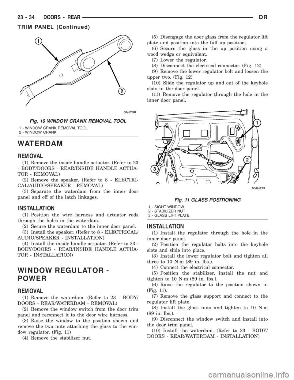
(3) Raise the window to the position shown and
remove the two nuts attaching the glass to the win-
dow regulator. (Fig. 11)
(4) Remove the stabilizer nut.(5) Disengage the door glass from the regulator lift
plate and position into the full up position.
(6) Secure the glass in the up position using a
wood wedge or equivalent.
(7) Lower the regulator.
(8) Disconnect the electrical connector. (Fig. 12)
(9) Remove the lower regulator bolt and loosen the
upper two. (Fig. 12)
(10) Slide the regulator up and out of the keyhole
slots in the door panel.
(11) Remove the regulator through the hole in the
inner door panel.
INSTALLATION
(1) Install the regulator through the hole in the
inner door panel.
(2) Position the regulator bolts into the keyhole
slots and slide into place.
(3) Install the lower regulator bolt and tighten all
three to 10 N´m (89 in. lbs.).
(4) Connect the electrical connector.
(5) Position the stabilizer, install the nut and
tighten to 10 N´m (89 in. lbs.).
(6) Raise the regulator to the position shown in
(Fig. 11).
(7) Remove the glass support and connect to the
regulator lift plate.
(8) Install the glass nuts and tighten to 10 N´m
(89 in. lbs.).
(9) Disconnect the window switch and install into
the door trim panel.
(10) Install the waterdam. (Refer to 23 - BODY/
DOORS - REAR/WATERDAM - INSTALLATION)
Fig. 10 WINDOW CRANK REMOVAL TOOL
1 - WINDOW CRANK REMOVAL TOOL
2 - WINDOW CRANK
Fig. 11 GLASS POSITIONING
1 - SIGHT WINDOW
2 - STABILIZER NUT
3 - GLASS LIFT PLATE
23 - 34 DOORS - REARDR
TRIM PANEL (Continued)
Page 2629 of 2895
(2) Remove the top cover. (Refer to 23 - BODY/IN-
STRUMENT PANEL/INSTRUMENT PANEL TOP
COVER - REMOVAL)
(3) Disconnect the headliner harness electrical con-
nector at the a-pillar.
(4) Using a trim stick C-4755 or equivalent, from
the notch on the bottom, remove the left side cover.
(Fig. 20)
(5) Remove the steering column. (Refer to 19 -
STEERING/COLUMN - REMOVAL)
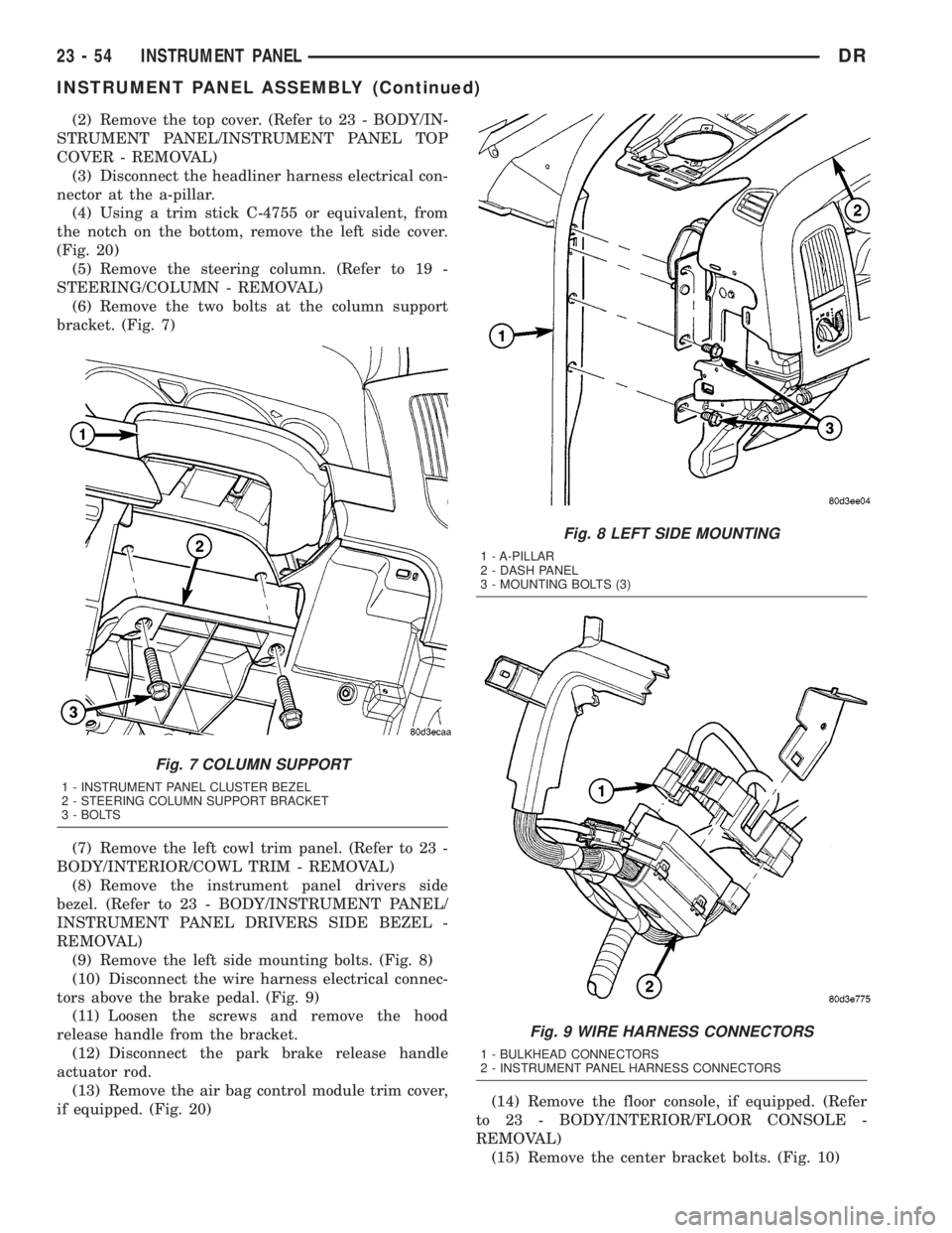
(6) Remove the two bolts at the column support
bracket. (Fig. 7)
(7) Remove the left cowl trim panel. (Refer to 23 -
BODY/INTERIOR/COWL TRIM - REMOVAL)
(8) Remove the instrument panel drivers side
bezel. (Refer to 23 - BODY/INSTRUMENT PANEL/
INSTRUMENT PANEL DRIVERS SIDE BEZEL -
REMOVAL)
(9) Remove the left side mounting bolts. (Fig. 8)
(10) Disconnect the wire harness electrical connec-
tors above the brake pedal. (Fig. 9)
(11) Loosen the screws and remove the hood
release handle from the bracket.
(12) Disconnect the park brake release handle
actuator rod.
(13) Remove the air bag control module trim cover,
if equipped. (Fig. 20)(14) Remove the floor console, if equipped. (Refer
to 23 - BODY/INTERIOR/FLOOR CONSOLE -
REMOVAL)
(15) Remove the center bracket bolts. (Fig. 10)
Fig. 7 COLUMN SUPPORT
1 - INSTRUMENT PANEL CLUSTER BEZEL
2 - STEERING COLUMN SUPPORT BRACKET
3 - BOLTS
Fig. 8 LEFT SIDE MOUNTING
1 - A-PILLAR
2 - DASH PANEL
3 - MOUNTING BOLTS (3)
Fig. 9 WIRE HARNESS CONNECTORS
1 - BULKHEAD CONNECTORS
2 - INSTRUMENT PANEL HARNESS CONNECTORS
23 - 54 INSTRUMENT PANELDR
INSTRUMENT PANEL ASSEMBLY (Continued)
Page 2776 of 2895
HEATING & AIR CONDITIONING
TABLE OF CONTENTS
page page
HEATING & AIR CONDITIONING
DESCRIPTION
DESCRIPTION - HEATER AND AIR
CONDITIONER........................1
DESCRIPTION - COOLING SYSTEM
REQUIREMENTS.......................1
DESCRIPTION - REFRIGERANT SYSTEM
SERVICE PORT........................1
OPERATION
OPERATION - HEATER AND AIR
CONDITIONER........................1
OPERATION - REFRIGERANT SYSTEM
SERVICE PORT........................2DIAGNOSIS AND TESTING
DIAGNOSIS AND TESTING - A/C
PERFORMANCE.......................2
DIAGNOSIS AND TESTING - HEATER
PERFORMANCE.......................5
STANDARD PROCEDURE - DIODE
REPLACEMENT.......................7
SPECIFICATIONS
A/C APPLICATION TABLE................7
SPECIFICATIONS......................8
CONTROLS.............................9
DISTRIBUTION..........................24
PLUMBING.............................31
HEATING & AIR
CONDITIONING
DESCRIPTION
DESCRIPTION - HEATER AND AIR
CONDITIONER
All vehicles are equipped with a common HVAC
housing assembly (Fig. 1). The system combines air
conditioning, heating, and ventilating capabilities in
a single unit housing mounted under the instrument
panel.
DESCRIPTION - COOLING SYSTEM
REQUIREMENTS
To maintain the performance level of the HVAC
system, the engine cooling system must be properly
maintained. The use of a bug screen is not recom-
mended. Any obstructions in front of the radiator or
condenser will reduce the performance of the air con-
ditioning and engine cooling systems.
The engine cooling system includes the heater core
and the heater hoses. Refer to Engine Cooling for
more information before the opening of, or attempt-
ing any service to the engine cooling system.
DESCRIPTION - REFRIGERANT SYSTEM
SERVICE PORT
The two refrigerant system service ports are used
to charge, recover/recycle, evacuate, and test the air
conditioning refrigerant system. Unique service port
coupler sizes are used on the R-134a system, toensure that the refrigerant system is not accidentally
contaminated by the use of the wrong refrigerant
(R-12), or refrigerant system service equipment.
OPERATION
OPERATION - HEATER AND AIR CONDITIONER
The heater air conditioner are blend-air type sys-
tems. In a blend-air system, a blend door controls the
amount of unconditioned air (or cooled air from the
evaporator on models with air conditioning) that is
allowed to flow through, or around, the heater core. A
temperature control knob on the A/C Heater control
panel determines the discharge air temperature by
controlling an electric actuator, which moves the
blend door. This allows an almost immediate control
of the output air temperature of the system.
The mode control knob on the A/C Heater control
panel is used to direct the conditioned air to the
selected system outlets. Both mode control switches
use electric actuators to control the mode doors.
On all vehicles, the outside air intake can be shut
off by selecting the Recirculation Mode with the
mode control knob. This will operate a electric actu-
ated recirculation door that closes off the outside
fresh air intake and recirculates the air that is
already inside the vehicle.
The air conditioner for all models is designed for
the use of non-CFC, R-134a refrigerant. The air con-
ditioning system has an evaporator to cool and dehu-
midify the incoming air prior to blending it with the
heated air. This air conditioning system uses a fixed
orifice tube in the liquid line near the condenser out-
let tube to meter refrigerant flow to the evaporator
DRHEATING & AIR CONDITIONING 24 - 1
Page 2777 of 2895
coil. To maintain minimum evaporator temperature
and prevent evaporator freezing, the A/C Fin Probe
which is located in the evaporator cycles the com-
pressor clutch by sending an A/C request to the
JTEC which in turn processes this piece of informa-
tion and if all conditions are met cycles the compres-
sor clutch.
OPERATION - REFRIGERANT SYSTEM SERVICE
PORT
The low pressure service port is located on the suc-
tion refrigerant line, near the accumulator. The high
pressure service port is located on the liquid line at
the passenger side of the engine compartment, near
the condenser.
Each of the service ports has a threaded plastic
protective cap installed over it from the factory. After
servicing the refrigerant system, always reinstall
both of the service port caps.
DIAGNOSIS AND TESTING
DIAGNOSIS AND TESTING - A/C
PERFORMANCE
The air conditioning system is designed to provide
the passenger compartment with low temperature
and low humidity air. The evaporator, located in the
HVAC housing on the dash panel below the instru-
ment panel, is cooled to temperatures near the freez-
ing point. As warm damp air passes through the
cooled evaporator, the air transfers its heat to the
refrigerant in the evaporator and the moisture in the
air condenses on the evaporator fins. During periods
of high heat and humidity, an air conditioning sys-
tem will be more effective in the Recirculation Mode.
With the system in the Recirculation Mode, only air
from the passenger compartment passes through the
evaporator. As the passenger compartment air dehu-
midifies, the air conditioning system performance
levels improve.
Humidity has an important bearing on the temper-
ature of the air delivered to the interior of the vehi-
cle. It is important to understand the effect that
humidity has on the performance of the air condition-
ing system. When humidity is high, the evaporator
has to perform a double duty. It must lower the air
temperature, and it must lower the temperature of
the moisture in the air that condenses on the evapo-
rator fins. Condensing the moisture in the air trans-
fers heat energy into the evaporator fins and tubing.
This reduces the amount of heat the evaporator can
absorb from the air. High humidity greatly reduces
the ability of the evaporator to lower the temperature
of the air.
However, evaporator capacity used to reduce the
amount of moisture in the air is not wasted. Remov-
ing some of the moisture out of the air entering the
vehicle adds to the comfort of the passengers.
Although, an owner may expect too much from the
air conditioning system on humid days. A perfor-
mance test is the best way to determine whether the
system is performing up to standard. This test also
provides valuable clues as to the possible cause of
trouble with the air conditioning system.
Before proceeding, (Refer to 24 - HEATING & AIR
CONDITIONING/PLUMBING - WARNING) and
(Refer to 24 - HEATING & AIR CONDITIONING/
PLUMBING - CAUTION). The air temperature in
the test room and in the vehicle must be a minimum
of 21É C (70É F) for this test.
(1) Connect a tachometer and a manifold gauge set
or A/C recycling/charging station.
(2) Set the A/C Heater mode control switch knob in
the Recirculation Mode position, the temperature
control knob in the full cool position, and the blower
motor switch knob in the highest speed position.
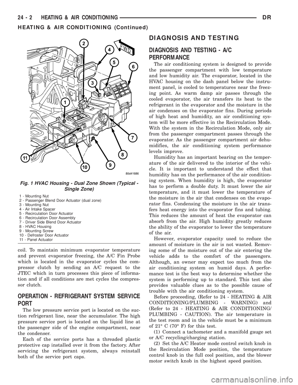
Fig. 1 HVAC Housing - Dual Zone Shown (Typical -
Single Zone)
1 - Mounting Nut
2 - Passenger Blend Door Actuator (dual zone)
3 - Mounting Nut
4 - Air Intake Spacer
5 - Recirculation Door Actuator
6 - Recirculation Door Assembly
7 - Driver Side Blend Door Actuator
8 - HVAC Housing
9 - Mounting Screw
10 - Defroster Door Actuator
11 - Panel Actuator
24 - 2 HEATING & AIR CONDITIONINGDR
HEATING & AIR CONDITIONING (Continued)
Page 2779 of 2895
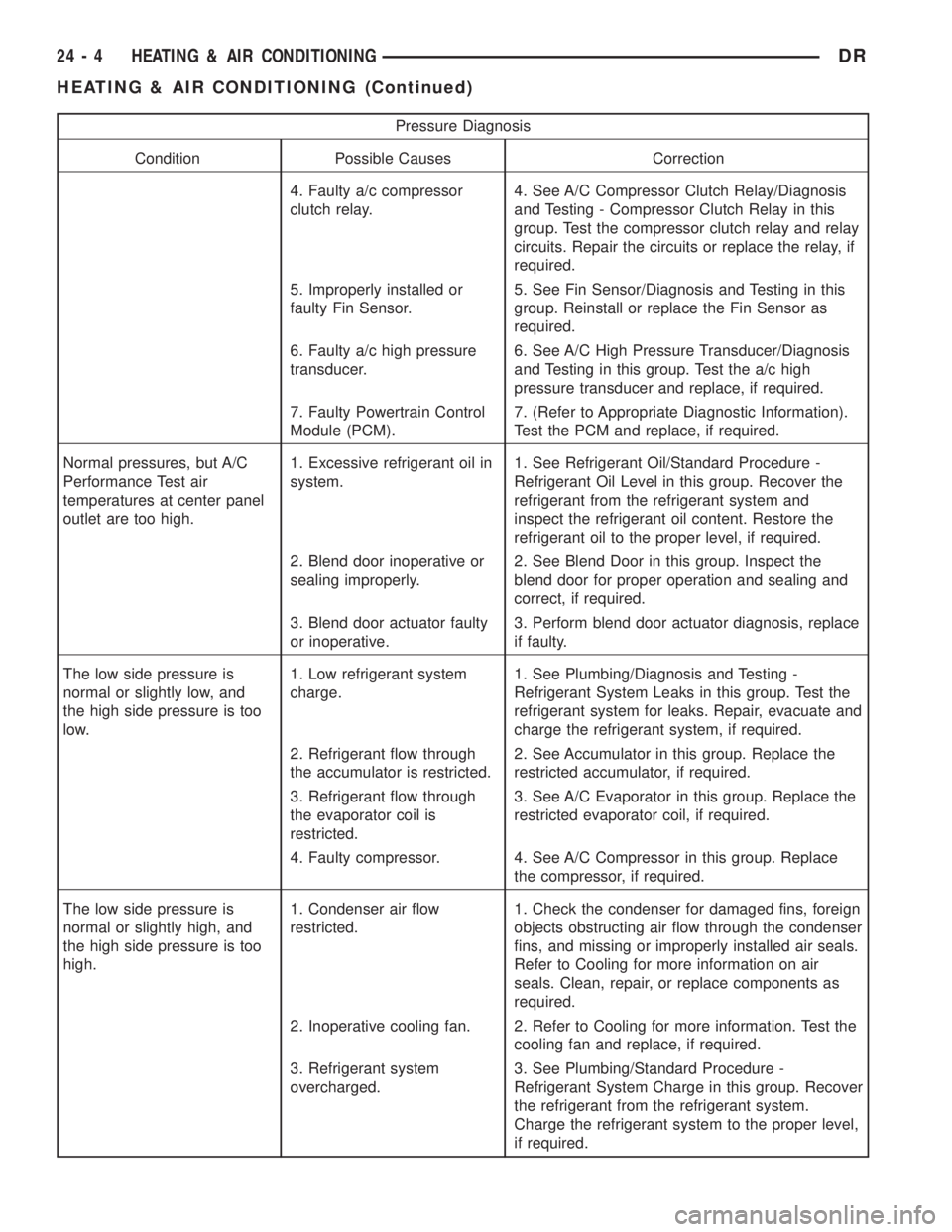
Pressure Diagnosis
Condition Possible Causes Correction
4. Faulty a/c compressor
clutch relay.4. See A/C Compressor Clutch Relay/Diagnosis
and Testing - Compressor Clutch Relay in this
group. Test the compressor clutch relay and relay
circuits. Repair the circuits or replace the relay, if
required.
5. Improperly installed or
faulty Fin Sensor.5. See Fin Sensor/Diagnosis and Testing in this
group. Reinstall or replace the Fin Sensor as
required.
6. Faulty a/c high pressure
transducer.6. See A/C High Pressure Transducer/Diagnosis
and Testing in this group. Test the a/c high
pressure transducer and replace, if required.
7. Faulty Powertrain Control
Module (PCM).7. (Refer to Appropriate Diagnostic Information).
Test the PCM and replace, if required.
Normal pressures, but A/C
Performance Test air
temperatures at center panel
outlet are too high.1. Excessive refrigerant oil in
system.1. See Refrigerant Oil/Standard Procedure -
Refrigerant Oil Level in this group. Recover the
refrigerant from the refrigerant system and
inspect the refrigerant oil content. Restore the
refrigerant oil to the proper level, if required.
2. Blend door inoperative or
sealing improperly.2. See Blend Door in this group. Inspect the
blend door for proper operation and sealing and
correct, if required.
3. Blend door actuator faulty
or inoperative.3. Perform blend door actuator diagnosis, replace
if faulty.
The low side pressure is
normal or slightly low, and
the high side pressure is too
low.1. Low refrigerant system
charge.1. See Plumbing/Diagnosis and Testing -
Refrigerant System Leaks in this group. Test the
refrigerant system for leaks. Repair, evacuate and
charge the refrigerant system, if required.
2. Refrigerant flow through
the accumulator is restricted.2. See Accumulator in this group. Replace the
restricted accumulator, if required.
3. Refrigerant flow through
the evaporator coil is
restricted.3. See A/C Evaporator in this group. Replace the
restricted evaporator coil, if required.
4. Faulty compressor. 4. See A/C Compressor in this group. Replace
the compressor, if required.
The low side pressure is
normal or slightly high, and
the high side pressure is too
high.1. Condenser air flow
restricted.1. Check the condenser for damaged fins, foreign
objects obstructing air flow through the condenser
fins, and missing or improperly installed air seals.
Refer to Cooling for more information on air
seals. Clean, repair, or replace components as
required.
2. Inoperative cooling fan. 2. Refer to Cooling for more information. Test the
cooling fan and replace, if required.
3. Refrigerant system
overcharged.3. See Plumbing/Standard Procedure -
Refrigerant System Charge in this group. Recover
the refrigerant from the refrigerant system.
Charge the refrigerant system to the proper level,
if required.
24 - 4 HEATING & AIR CONDITIONINGDR
HEATING & AIR CONDITIONING (Continued)
Page 2781 of 2895
If the floor outlet air temperature is too low, refer
to Cooling to check the engine coolant temperature
specifications. Both of the heater hoses should be hot
to the touch. The coolant return heater hose should
be slightly cooler than the coolant supply heater
hose. If the return hose is much cooler than the sup-
ply hose, locate and repair the engine coolant flow
obstruction in the cooling system. Refer to Cooling
for the procedures.
An alternate method of checking heater perfor-
mance is to use a DRBIIItscan tool to monitor the
engine coolant temperature. The floor outlet air tem-
perature reading should be no more than 4.5É C (40É
F) lower than the engine coolant temperature read-
ing.
OBSTRUCTED COOLANT FLOW Possible loca-
tions or causes of obstructed coolant flow:
²Faulty water pump.
²Faulty thermostat.
²Pinched or kinked heater hoses.
²Improper heater hose routing.
²Plugged heater hoses or supply and return ports
at the cooling system connections.
²A plugged heater core.If proper coolant flow through the cooling system is
verified, and heater outlet air temperature is still
low, a mechanical problem may exist.
MECHANICAL PROBLEMS Possible locations or
causes of insufficient heat:
²An obstructed cowl air intake.
²Obstructed heater system outlets.
²A faulty, obstructed or improperly installed
blend door.
²A faulty blower system.
²A faulty a/c heater control.
TEMPERATURE CONTROL
If the heater outlet air temperature cannot be
adjusted with the temperature control knob on the
a/c heater control panel, the following could require
service:
²A faulty a/c heater control.
²A faulty blend door actuator.
²A faulty, obstructed or improperly installed
blend door.
²An obstructed cowl air intake.
²The engine cooling system.
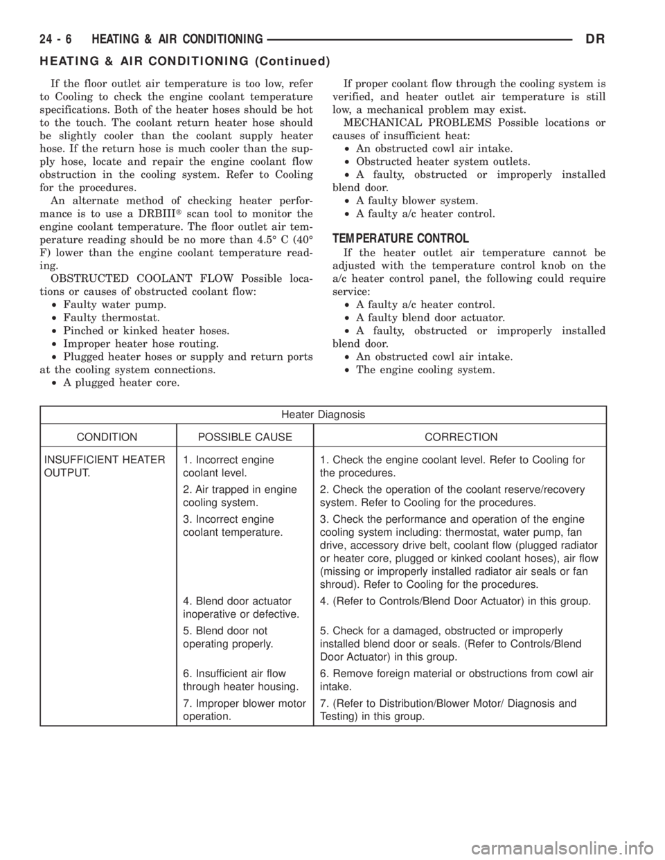
Heater Diagnosis
CONDITION POSSIBLE CAUSE CORRECTION
INSUFFICIENT HEATER
OUTPUT.1. Incorrect engine
coolant level.1. Check the engine coolant level. Refer to Cooling for
the procedures.
2. Air trapped in engine
cooling system.2. Check the operation of the coolant reserve/recovery
system. Refer to Cooling for the procedures.
3. Incorrect engine
coolant temperature.3. Check the performance and operation of the engine
cooling system including: thermostat, water pump, fan
drive, accessory drive belt, coolant flow (plugged radiator
or heater core, plugged or kinked coolant hoses), air flow
(missing or improperly installed radiator air seals or fan
shroud). Refer to Cooling for the procedures.
4. Blend door actuator
inoperative or defective.4. (Refer to Controls/Blend Door Actuator) in this group.
5. Blend door not
operating properly.5. Check for a damaged, obstructed or improperly
installed blend door or seals. (Refer to Controls/Blend
Door Actuator) in this group.
6. Insufficient air flow
through heater housing.6. Remove foreign material or obstructions from cowl air
intake.
7. Improper blower motor
operation.7. (Refer to Distribution/Blower Motor/ Diagnosis and
Testing) in this group.
24 - 6 HEATING & AIR CONDITIONINGDR
HEATING & AIR CONDITIONING (Continued)
Page 2782 of 2895
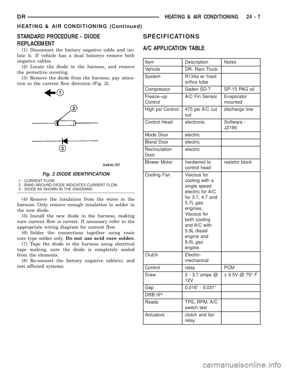
STANDARD PROCEDURE - DIODE
REPLACEMENT
(1) Disconnect the battery negative cable and iso-
late it. If vehicle has a dual batterys remove both
negative cables.
(2) Locate the diode in the harness, and remove
the protective covering.
(3) Remove the diode from the harness, pay atten-
tion to the current flow direction (Fig. 2).
(4) Remove the insulation from the wires in the
harness. Only remove enough insulation to solder in
the new diode.
(5) Install the new diode in the harness, making
sure current flow is correct. If necessary refer to the
appropriate wiring diagram for current flow.
(6) Solder the connections together using rosin
core type solder only.Do not use acid core solder.
(7) Tape the diode to the harness using electrical
tape making, sure the diode is completely sealed
from the elements.
(8) Re-connect the battery negative cable(s), and
test affected systems.
SPECIFICATIONS
A/C APPLICATION TABLE
Item Description Notes
Vehicle DR- Ram Truck
System R134a w/ fixed
orifice tube
Compressor Saden SD-7 SP-15 PAG oil
Freeze±up
ControlA/C Fin Sensor Evaporator
mounted
High psi Control 475 psi A/C cut
outdischarge line
Control Head electronic Software -
J2190
Mode Door electric
Blend Door electric
Recirculation
Doorelectric
Blower Motor hardwired to
control headresistor block
Cooling Fan Viscous for
cooling with a
single speed
electric for A/C
for 3.7, 4.7 and
5.7L gas
engines.
Viscous for
both cooling
and A/C with
5.9L diesel
engine and
8.0L gas
engine.
Clutch Electro-
mechanical
Control relay PCM
Draw 2 - 3.7 amps @
12V 0.5V @ 70É F
Gap 0.0169- 0.0319
DRB IIIT
Reads TPS, RPM, A/C
switch test
Actuators clutch and fan
relay
Fig. 2 DIODE IDENTIFICATION
1 - CURRENT FLOW
2 - BAND AROUND DIODE INDICATES CURRENT FLOW
3 - DIODE AS SHOWN IN THE DIAGRAMS
DRHEATING & AIR CONDITIONING 24 - 7
HEATING & AIR CONDITIONING (Continued)