2500 DODGE RAM 2003 Service Repair Manual
[x] Cancel search | Manufacturer: DODGE, Model Year: 2003, Model line: RAM, Model: DODGE RAM 2003Pages: 2895, PDF Size: 83.15 MB
Page 3 of 2895
VEHICLE IDENTIFICATION
NUMBER
DESCRIPTION
VIN CODING/LOCATIONS
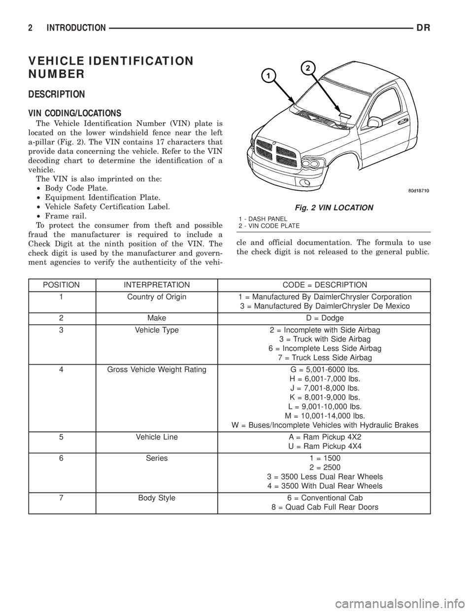
The Vehicle Identification Number (VIN) plate is
located on the lower windshield fence near the left
a-pillar (Fig. 2). The VIN contains 17 characters that
provide data concerning the vehicle. Refer to the VIN
decoding chart to determine the identification of a
vehicle.
The VIN is also imprinted on the:
²Body Code Plate.
²Equipment Identification Plate.
²Vehicle Safety Certification Label.
²Frame rail.
To protect the consumer from theft and possible
fraud the manufacturer is required to include a
Check Digit at the ninth position of the VIN. The
check digit is used by the manufacturer and govern-
ment agencies to verify the authenticity of the vehi-cle and official documentation. The formula to use
the check digit is not released to the general public.
POSITION INTERPRETATION CODE = DESCRIPTION
1 Country of Origin 1 = Manufactured By DaimlerChrysler Corporation
3 = Manufactured By DaimlerChrysler De Mexico
2 Make D = Dodge
3 Vehicle Type 2 = Incomplete with Side Airbag
3 = Truck with Side Airbag
6 = Incomplete Less Side Airbag
7 = Truck Less Side Airbag
4 Gross Vehicle Weight Rating G = 5,001-6000 lbs.
H = 6,001-7,000 lbs.
J = 7,001-8,000 lbs.
K = 8,001-9,000 lbs.
L = 9,001-10,000 lbs.
M = 10,001-14,000 lbs.
W = Buses/Incomplete Vehicles with Hydraulic Brakes
5 Vehicle Line A = Ram Pickup 4X2
U = Ram Pickup 4X4
6 Series 1 = 1500
2 = 2500
3 = 3500 Less Dual Rear Wheels
4 = 3500 With Dual Rear Wheels
7 Body Style 6 = Conventional Cab
8 = Quad Cab Full Rear Doors
Fig. 2 VIN LOCATION
1 - DASH PANEL
2 - VIN CODE PLATE
2 INTRODUCTIONDR
Page 5 of 2895
BODY CODE PLATE
DESCRIPTION
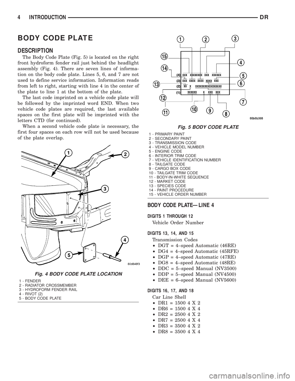
The Body Code Plate (Fig. 5) is located on the right
front hydroform fender rail just behind the headlight
assembly (Fig. 4). There are seven lines of informa-
tion on the body code plate. Lines 5, 6, and 7 are not
used to define service information. Information reads
from left to right, starting with line 4 in the center of
the plate to line 1 at the bottom of the plate.
The last code imprinted on a vehicle code plate will
be followed by the imprinted word END. When two
vehicle code plates are required, the last available
spaces on the first plate will be imprinted with the
letters CTD (for continued).
When a second vehicle code plate is necessary, the
first four spaces on each row will not be used because
of the plate overlap.
BODY CODE PLATEÐLINE 4
DIGITS 1 THROUGH 12
Vehicle Order Number
DIGITS 13, 14, AND 15
Transmission Codes
²DGT = 4±speed Automatic (46RE)
²DG4 = 4±speed Automatic (45RFE)
²DGP = 4±speed Automatic (47RE)
²DG8 = 4±speed Automatic (48RE)
²DDC = 5±speed Manual (NV3500)
²DDP = 5±speed Manual (NV4500)
²DEE = 6±speed Manual (NV5600)
DIGITS 16, 17, AND 18
Car Line Shell
²DR1=15004X2
²DR6=15004X4
²DR2=25004X2
²DR7=25004X4
²DR3=35004X2
²DR8=35004X4
Fig. 4 BODY CODE PLATE LOCATION
1 - FENDER
2 - RADIATOR CROSSMEMBER
3 - HYDROFORM FENDER RAIL
4 - RIVOT (2)
5 - BODY CODE PLATE
Fig. 5 BODY CODE PLATE
1 - PRIMARY PAINT
2 - SECONDARY PAINT
3 - TRANSMISSION CODE
4 - VEHICLE MODEL NUMBER
5 - ENGINE CODE
6 - INTERIOR TRIM CODE
7 - VEHICLE IDENTIFICATION NUMBER
8 - TAILGATE CODE
9 - CARGO BOX CODE
10 - TAILGATE TRIM CODE
11 - BODY-IN-WHITE SEQUENCE
12 - MARKET CODE
13 - SPECIES CODE
14 - PAINT PROCEDURE
15 - VEHICLE ORDER NUMBER
4 INTRODUCTIONDR
Page 20 of 2895
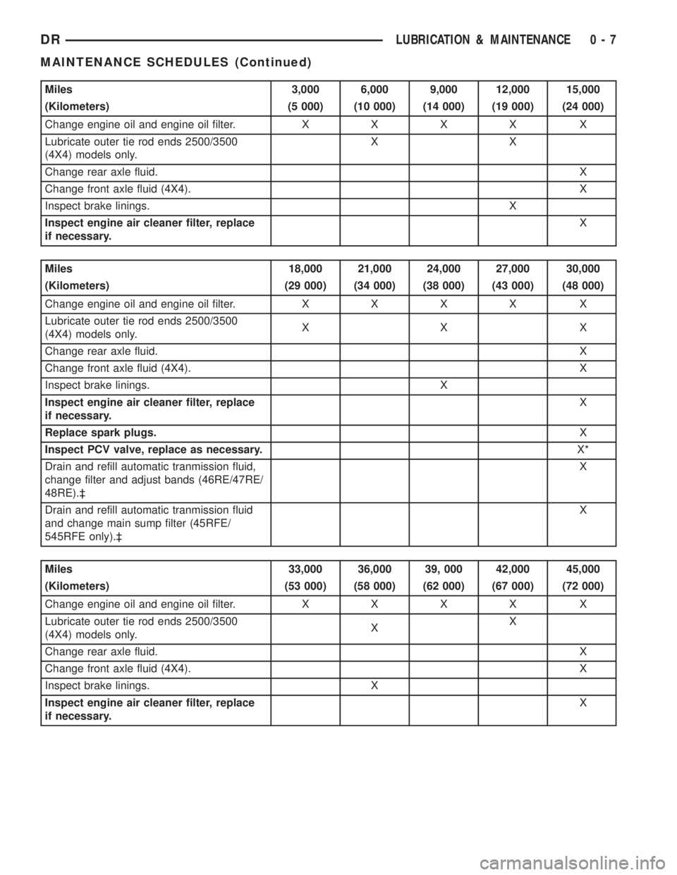
Miles 3,000 6,000 9,000 12,000 15,000
(Kilometers) (5 000) (10 000) (14 000) (19 000) (24 000)
Change engine oil and engine oil filter.XXXX X
Lubricate outer tie rod ends 2500/3500
(4X4) models only.XX
Change rear axle fluid.X
Change front axle fluid (4X4).X
Inspect brake linings.X
Inspect engine air cleaner filter, replace
if necessary.X
Miles 18,000 21,000 24,000 27,000 30,000
(Kilometers) (29 000) (34 000) (38 000) (43 000) (48 000)
Change engine oil and engine oil filter.XXXX X
Lubricate outer tie rod ends 2500/3500
(4X4) models only.XX X
Change rear axle fluid.X
Change front axle fluid (4X4).X
Inspect brake linings. X
Inspect engine air cleaner filter, replace
if necessary.X
Replace spark plugs.X
Inspect PCV valve, replace as necessary.X*
Drain and refill automatic tranmission fluid,
change filter and adjust bands (46RE/47RE/
48RE).³X
Drain and refill automatic tranmission fluid
and change main sump filter (45RFE/
545RFE only).³X
Miles 33,000 36,000 39, 000 42,000 45,000
(Kilometers) (53 000) (58 000) (62 000) (67 000) (72 000)
Change engine oil and engine oil filter.XXXX X
Lubricate outer tie rod ends 2500/3500
(4X4) models only.XX
Change rear axle fluid.X
Change front axle fluid (4X4).X
Inspect brake linings. X
Inspect engine air cleaner filter, replace
if necessary.X
DRLUBRICATION & MAINTENANCE 0 - 7
MAINTENANCE SCHEDULES (Continued)
Page 21 of 2895
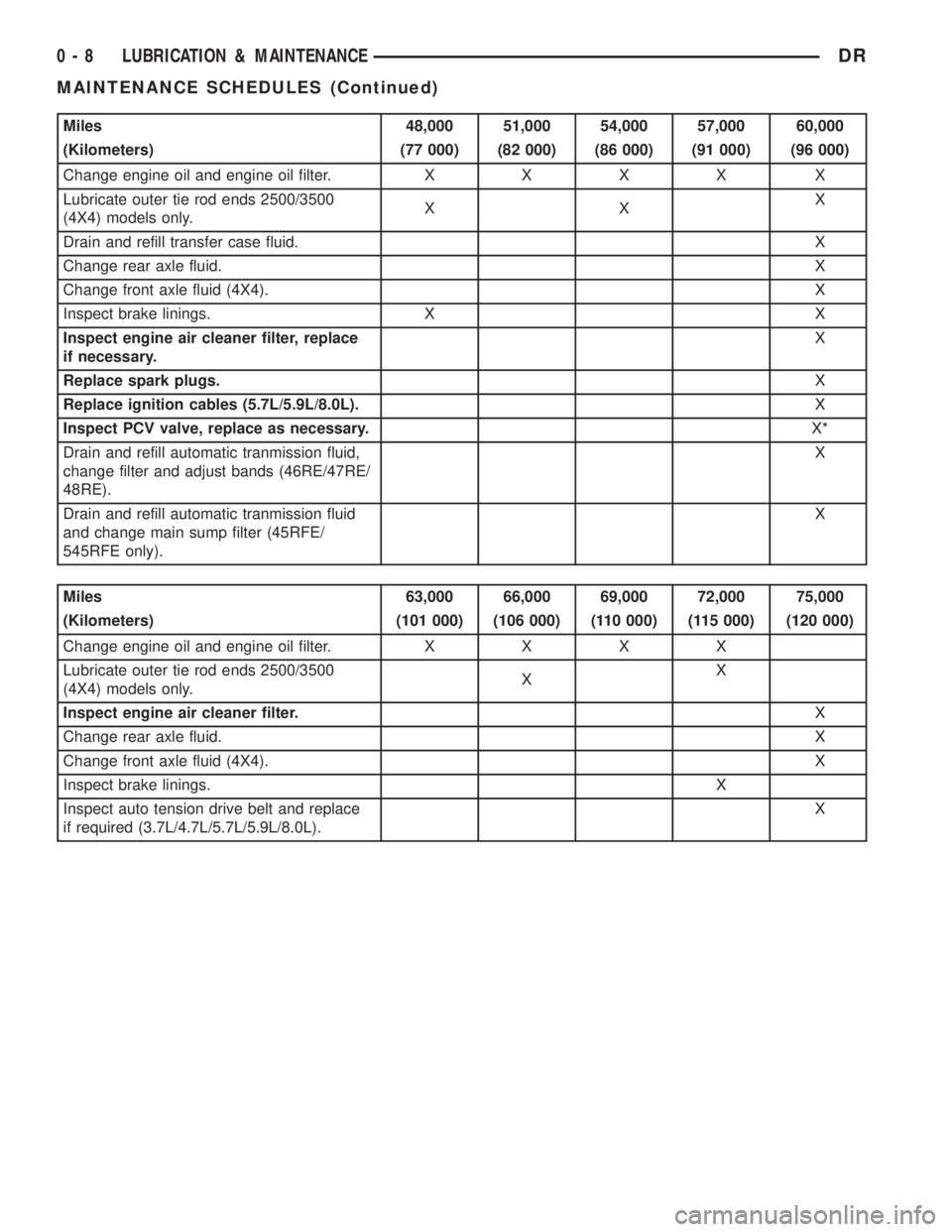
Miles 48,000 51,000 54,000 57,000 60,000
(Kilometers) (77 000) (82 000) (86 000) (91 000) (96 000)
Change engine oil and engine oil filter.XXXX X
Lubricate outer tie rod ends 2500/3500
(4X4) models only.XXX
Drain and refill transfer case fluid.X
Change rear axle fluid.X
Change front axle fluid (4X4).X
Inspect brake linings. X X
Inspect engine air cleaner filter, replace
if necessary.X
Replace spark plugs.X
Replace ignition cables (5.7L/5.9L/8.0L).X
Inspect PCV valve, replace as necessary.X*
Drain and refill automatic tranmission fluid,
change filter and adjust bands (46RE/47RE/
48RE).X
Drain and refill automatic tranmission fluid
and change main sump filter (45RFE/
545RFE only).X
Miles 63,000 66,000 69,000 72,000 75,000
(Kilometers) (101 000) (106 000) (110 000) (115 000) (120 000)
Change engine oil and engine oil filter.XXXX
Lubricate outer tie rod ends 2500/3500
(4X4) models only.XX
Inspect engine air cleaner filter.X
Change rear axle fluid.X
Change front axle fluid (4X4).X
Inspect brake linings.X
Inspect auto tension drive belt and replace
if required (3.7L/4.7L/5.7L/5.9L/8.0L).X
0 - 8 LUBRICATION & MAINTENANCEDR
MAINTENANCE SCHEDULES (Continued)
Page 22 of 2895
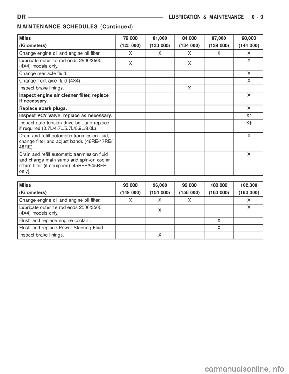
Miles 78,000 81,000 84,000 87,000 90,000
(Kilometers) (125 000) (130 000) (134 000) (139 000) (144 000)
Change engine oil and engine oil filter.XXXX X
Lubricate outer tie rod ends 2500/3500
(4X4) models only.XXX
Change rear axle fluid.X
Change front axle fluid (4X4).X
Inspect brake linings. X
Inspect engine air cleaner filter, replace
if necessary.X
Replace spark plugs.X
Inspect PCV valve, replace as necessary.X*
Inspect auto tension drive belt and replace
if required (3.7L/4.7L/5.7L/5.9L/8.0L).X³
Drain and refill automatic tranmission fluid,
change filter and adjust bands (46RE/47RE/
48RE).X
Drain and refill automatic tranmission fluid
and change main sump and spin-on cooler
return filter (if equipped) [45RFE/545RFE
only].X
Miles 93,000 96,000 99,000 100,000 102,000
(Kilometers) (149 000) (154 000) (158 000) (160 000) (163 000)
Change engine oil and engine oil filter. X X X X
Lubricate outer tie rod ends 2500/3500
(4X4) models only.XX
Flush and replace engine coolant. X
Flush and replace Power Steering Fluid. X
Inspect brake linings. X
DRLUBRICATION & MAINTENANCE 0 - 9
MAINTENANCE SCHEDULES (Continued)
Page 23 of 2895
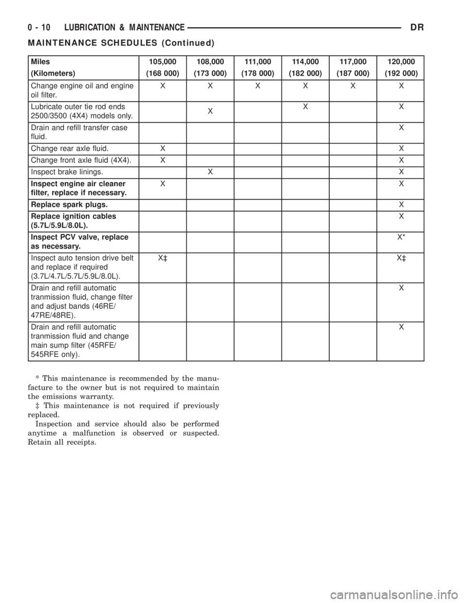
Miles 105,000 108,000 111,000 114,000 117,000 120,000
(Kilometers) (168 000) (173 000) (178 000) (182 000) (187 000) (192 000)
Change engine oil and engine
oil filter.XXXXX X
Lubricate outer tie rod ends
2500/3500 (4X4) models only.XXX
Drain and refill transfer case
fluid.X
Change rear axle fluid. X X
Change front axle fluid (4X4). X X
Inspect brake linings. X X
Inspect engine air cleaner
filter, replace if necessary.XX
Replace spark plugs.X
Replace ignition cables
(5.7L/5.9L/8.0L).X
Inspect PCV valve, replace
as necessary.X*
Inspect auto tension drive belt
and replace if required
(3.7L/4.7L/5.7L/5.9L/8.0L).X³ X³
Drain and refill automatic
tranmission fluid, change filter
and adjust bands (46RE/
47RE/48RE).X
Drain and refill automatic
tranmission fluid and change
main sump filter (45RFE/
545RFE only).X
* This maintenance is recommended by the manu-
facture to the owner but is not required to maintain
the emissions warranty.
³ This maintenance is not required if previously
replaced.
Inspection and service should also be performed
anytime a malfunction is observed or suspected.
Retain all receipts.
0 - 10 LUBRICATION & MAINTENANCEDR
MAINTENANCE SCHEDULES (Continued)
Page 24 of 2895

Schedule ªAº
Miles 6,000 12,000 18,000 24,000 30,000
(Kilometers) (10 000) (19 000) (29 000) (38 000) (48 000)
[Months] [6] [12] [18] [24] [30]
Change engine oil and engine oil filter.XXXX X
Check transfer case fluid level.X
Lubricate outer tie rod ends 2500/3500
(4X4) models only.XXXX X
Inspect brake linings. X
Replace engine air cleaner filter.X
Replace spark plugs.X
Miles 36,000 42,000 48,000 54,000 60,000 66,000
(Kilometers) (58 000) (67 000) (77 000) (84 000) (96 000) (106 000)
[Months] [36] [42] [48] [54] [60] [66]
Change engine oil and engine
oil filter.XXXXX
X
Check transfer case fluid
level.X
Lubricate outer tie rod ends
2500/3500 (4X4) models only.XXXXX X
Flush and replace engine
coolant at 60 months,
regardless of mileage.X
Inspect brake linings. X X
Replace engine air cleaner
filter.X
Replace spark plugs.X
Inspect PCV valve, replace
as necessary.X*
Replace ignition cables
(5.7L/5.9L/8.0L).X
DRLUBRICATION & MAINTENANCE 0 - 11
MAINTENANCE SCHEDULES (Continued)
Page 25 of 2895

Miles 72,000 78,000 84,000 90,000 96,000 100,000
(Kilometers) (115 000) (125 000) (134 000) (144 000) (154 000) (160 000)
[Months] [72] [78] [84] [90] [96]
Change engine oil and engine oil filter.XXXXX
Lubricate outer tie rod ends 2500/3500
(4X4) models only.XXXXX
Drain and refill transfer case fluid. X
Flush and replace engine coolant, if not
done at 60 mos.X
Flush and replace Power Steering Fluid.X
Inspect brake linings. X X
Replace engine air cleaner filter.X
Replace spark plugs.X
Replace ignition cables (5.7L/5.9L/
8.0L).X
Inspect PCV valve, replace as
necessary.X*
Inspect auto tension drive belt and
replace if required (3.7L/4.7L/5.7L/5.9L/
8.0L).X
Drain and refill automatic tranmission
fluid, change filter and adjust bands
(46RE/47RE/48RE).X
Drain and refill automatic tranmission
fluid and change main sump filter and
spin-on cooler return filter (if equipped)
[45RFE/545RFE only].X
Miles 102,000 108,000 114,000 120,000
(Kilometers) (163 000) (173 000) (182 000) (192 000)
[Months] [102] [108] [114] [120]
Change engine oil and engine oil filter. X X X X
Check transfer case fluid level.X
Lubricate outer tie rod ends 2500/3500 (4X4) models only. X X X X
Inspect brake linings. X
Inspect auto tension drive belt and replace if required
(3.7L/4.7L/5.7L/5.9L/8.0L).X³X³
Replace engine air cleaner filter.X
Replace spark plugs.X
* This maintenance is recommended by the manu-
facture to the owner but is not required to maintain
the emissions warranty.
³ This maintenance is not required if previously
replaced.
Inspection and service should also be performed
anytime a malfunction is observed or suspected.
Retain all receipts.WARNING: You can be badly injured working on or
around a motor vehicle. Do only that service work
for which you have the knowledge and the right
equipment. If you have any doubt about your ability
to perform a service job, take your vehicle to a
competent mechanic.
0 - 12 LUBRICATION & MAINTENANCEDR
MAINTENANCE SCHEDULES (Continued)
Page 33 of 2895
To adjust the vehicle height turn the torsion bar
adjustment bolt CLOCKWISE to raise the vehicle
and COUNTER CLOCKWISE to lower the vehicle.
CAUTION: ALWAYS raise the vehicle to the correct
suspension height, NEVER lower the vehicle to
obtain the correct suspension height. If the vehicle
suspension height is too high, lower the vehicle
below the height specification. Then raise the vehi-
cle to the correct suspension height specification.
This will insure the vehicle maintains the proper
suspension height.
NOTE: If a height adjustment has been made, per-
form height measurement again on both sides of
the vehicle.
STANDARD PROCEDURE - CAMBER AND
CASTER ADJUSTMENT
NOTE: 4X4 (LD) SUSPENSION HEIGHT MEASURE-
MENT MUST BE PERFORMED BEFORE AN ALIGN-
MENT.
NOTE: When the upper control arm pivot bolts are
loosened the upper control arm will normally go
inwards toward the frame automatically with the
weight of the vehicle.
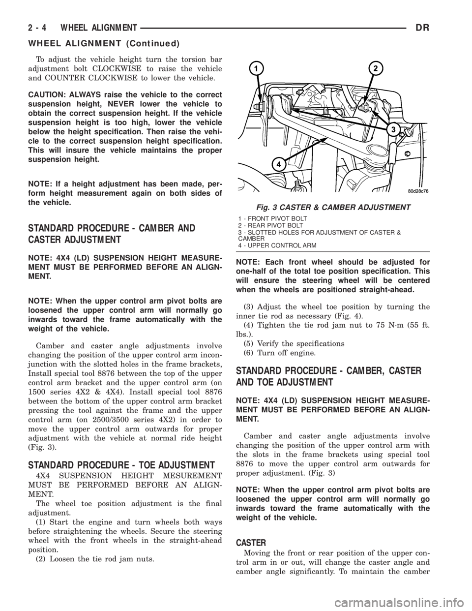
Camber and caster angle adjustments involve
changing the position of the upper control arm incon-
junction with the slotted holes in the frame brackets,
Install special tool 8876 between the top of the upper
control arm bracket and the upper control arm (on
1500 series 4X2 & 4X4). Install special tool 8876
between the bottom of the upper control arm bracket
pressing the tool against the frame and the upper
control arm (on 2500/3500 series 4X2) in order to
move the upper control arm outwards for proper
adjustment with the vehicle at normal ride height
(Fig. 3).
STANDARD PROCEDURE - TOE ADJUSTMENT
4X4 SUSPENSION HEIGHT MESUREMENT
MUST BE PERFORMED BEFORE AN ALIGN-
MENT.
The wheel toe position adjustment is the final
adjustment.
(1) Start the engine and turn wheels both ways
before straightening the wheels. Secure the steering
wheel with the front wheels in the straight-ahead
position.
(2) Loosen the tie rod jam nuts.NOTE: Each front wheel should be adjusted for
one-half of the total toe position specification. This
will ensure the steering wheel will be centered
when the wheels are positioned straight-ahead.
(3) Adjust the wheel toe position by turning the
inner tie rod as necessary (Fig. 4).
(4) Tighten the tie rod jam nut to 75 N´m (55 ft.
lbs.).
(5) Verify the specifications
(6) Turn off engine.
STANDARD PROCEDURE - CAMBER, CASTER
AND TOE ADJUSTMENT
NOTE: 4X4 (LD) SUSPENSION HEIGHT MEASURE-
MENT MUST BE PERFORMED BEFORE AN ALIGN-
MENT.
Camber and caster angle adjustments involve
changing the position of the upper control arm with
the slots in the frame brackets using special tool
8876 to move the upper control arm outwards for
proper adjustment. (Fig. 3)
NOTE: When the upper control arm pivot bolts are
loosened the upper control arm will normally go
inwards toward the frame automatically with the
weight of the vehicle.
CASTER
Moving the front or rear position of the upper con-
trol arm in or out, will change the caster angle and
camber angle significantly. To maintain the camber
Fig. 3 CASTER & CAMBER ADJUSTMENT
1 - FRONT PIVOT BOLT
2 - REAR PIVOT BOLT
3 - SLOTTED HOLES FOR ADJUSTMENT OF CASTER &
CAMBER
4 - UPPER CONTROL ARM
2 - 4 WHEEL ALIGNMENTDR
WHEEL ALIGNMENT (Continued)
Page 34 of 2895
angle while adjusting caster, move one pivot bolt of
the upper control arm in or out. Then move the other
pivot bolt of the upper control arm in the opposite
direction. Install special tool 8876 between the top of
the upper control arm bracket and the upper control
arm (on 1500 series 4X2 & 4X4). Install special tool
8876 between the bottom of the upper control arm
bracket pressing the tool against the frame and the
upper control arm (on 2500/3500 series 4X2) in order
to move the upper control arm outwards for proper
adjustment with the vehicle at normal ride height
(Fig. 3).
To increase positive caster angle, move the rear
position of the upper control arm inward (toward the
engine). Move the front of the upper control arm out-
ward (away from the engine) slightly until the origi-
nal camber angle is obtained using special tool 8876
to move the upper control arm for proper adjustment.
(Fig. 3)
CAMBER
Move both pivot bolts of the upper control arm
together in or out. This will change the camber angle
significantly and little effect on the caster angle
using special tool 8876 to move the upper control
arm for proper adjustment. (Fig. 3)
After adjustment is made tighten the upper control
arm nuts to proper torque specification.
TOE ADJUSTMENT
The wheel toe position adjustment is the final
adjustment.
(1) Start the engine and turn wheels both ways
before straightening the wheels. Secure the steering
wheel with the front wheels in the straight-ahead
position.
(2) Loosen the tie rod jam nuts.
NOTE: Each front wheel should be adjusted for
one-half of the total toe position specification. This
will ensure the steering wheel will be centered
when the wheels are positioned straight-ahead.
(3) Adjust the wheel toe position by turning the
inner tie rod as necessary (Fig. 4).
(4) Tighten the tie rod jam nut to 75 N´m (55 ft.
lbs.).
(5) Verify the specifications
(6) Turn off engine.
STANDARD PROCEDURE - ALIGNMENT
LINK/COIL SUSPENSION
Before each alignment reading the vehicle should
be jounced (rear first, then front). Grasp each
bumper at the center and jounce the vehicle up and
down several times. Always release the bumper inthe down position.Set the front end alignment to
specifications while the vehicle is in its NOR-
MALLY LOADED CONDITION.
CAMBER:The wheel camber angle is preset and
is not adjustable.
CASTER:Check the caster of the front axle for
correct angle. Be sure the axle is not bent or twisted.
Road test the vehicle and make left and right turn.
Observe the steering wheel return-to-center position.
Low caster will cause poor steering wheel returnabil-
ity.
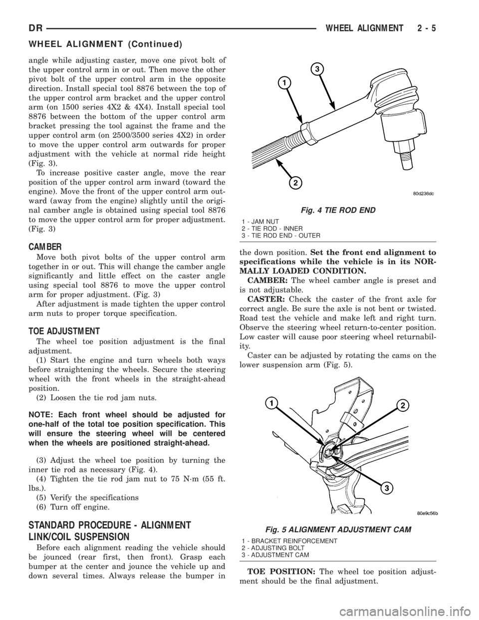
Caster can be adjusted by rotating the cams on the
lower suspension arm (Fig. 5).
TOE POSITION:The wheel toe position adjust-
ment should be the final adjustment.
Fig. 4 TIE ROD END
1 - JAM NUT
2 - TIE ROD - INNER
3 - TIE ROD END - OUTER
Fig. 5 ALIGNMENT ADJUSTMENT CAM
1 - BRACKET REINFORCEMENT
2 - ADJUSTING BOLT
3 - ADJUSTMENT CAM
DRWHEEL ALIGNMENT 2 - 5
WHEEL ALIGNMENT (Continued)