2500 DODGE RAM 2003 Service User Guide
[x] Cancel search | Manufacturer: DODGE, Model Year: 2003, Model line: RAM, Model: DODGE RAM 2003Pages: 2895, PDF Size: 83.15 MB
Page 35 of 2895
(1) Start the engine and turn wheels both ways
before straightening the wheels. Center and Secure
the steering wheel and turn off engine.
(2) Loosen the adjustment sleeve clamp bolts.
(3) Adjust the right wheel toe position with the
drag link. Turn the sleeve until the right wheel is at
the correct TOE-IN position. Position clamp bolts to
their original position and tighten to specifications.
Make sure the toe setting does not change dur-
ing clamp tightening.
(4) Adjust left wheel toe position with tie rod at
left knuckle. Turn the sleeve until the left wheel is at
the correct TOE-IN position. Position clamp bolts to
their original position and tighten to specifications.
Make sure the toe setting does not change dur-
ing clamp tightening.
(5) Verify the right toe setting and a straight steer-
ing wheel.
(6) Road test the vehicle.
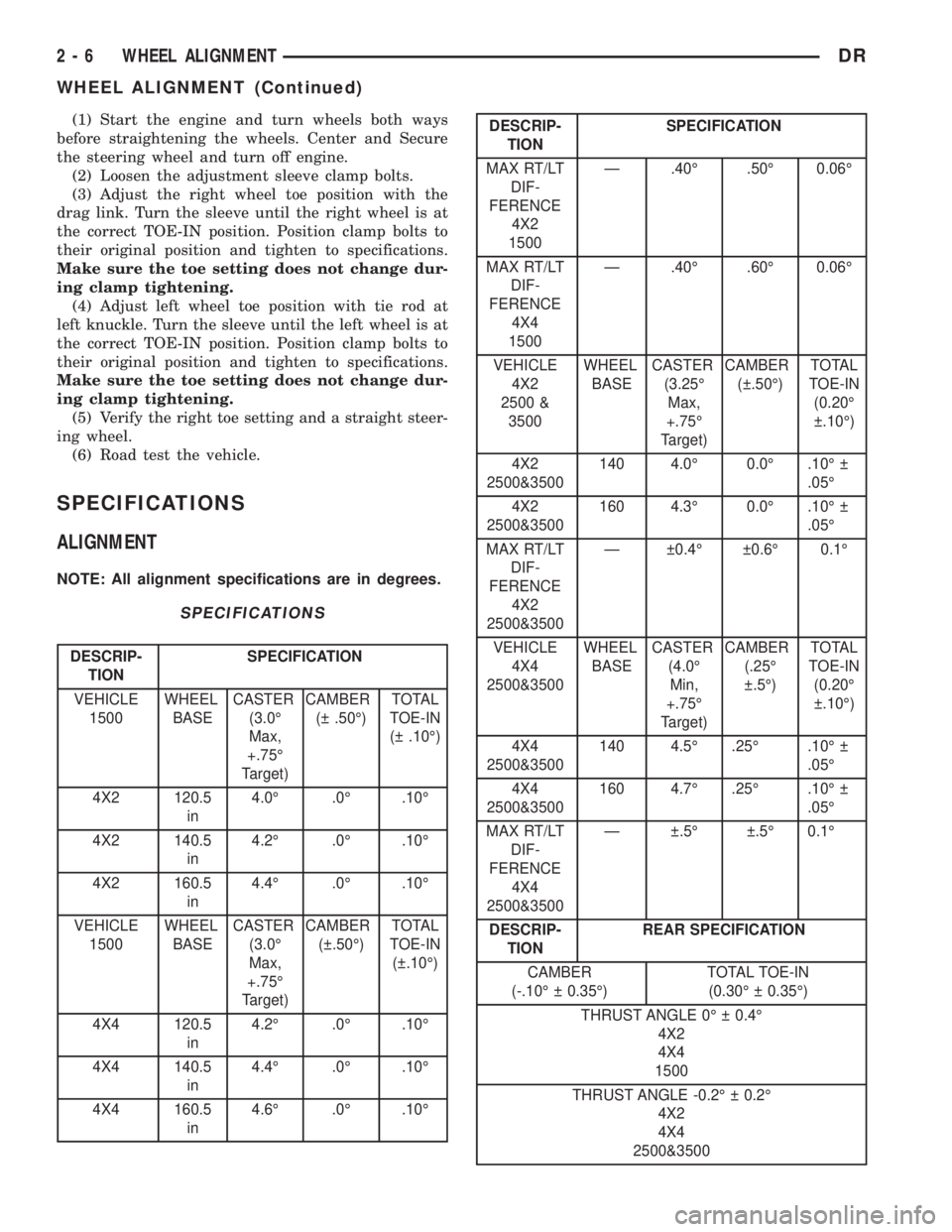
SPECIFICATIONS
ALIGNMENT
NOTE: All alignment specifications are in degrees.
SPECIFICATIONS
DESCRIP-
TIONSPECIFICATION
VEHICLE
1500WHEEL
BASECASTER
(3.0É
Max,
+.75É
Target)CAMBER
( .50É)TOTAL
TOE-IN
( .10É)
4X2 120.5
in4.0É .0É .10É
4X2 140.5
in4.2É .0É .10É
4X2 160.5
in4.4É .0É .10É
VEHICLE
1500WHEEL
BASECASTER
(3.0É
Max,
+.75É
Target)CAMBER
( .50É)TOTAL
TOE-IN
( .10É)
4X4 120.5
in4.2É .0É .10É
4X4 140.5
in4.4É .0É .10É
4X4 160.5
in4.6É .0É .10É
DESCRIP-
TIONSPECIFICATION
MAX RT/LT
DIF-
FERENCE
4X2
1500Ð .40É .50É 0.06É
MAX RT/LT
DIF-
FERENCE
4X4
1500Ð .40É .60É 0.06É
VEHICLE
4X2
2500 &
3500WHEEL
BASECASTER
(3.25É
Max,
+.75É
Target)CAMBER
( .50É)TOTAL
TOE-IN
(0.20É
.10É)
4X2
2500&3500140 4.0É 0.0É .10É
.05É
4X2
2500&3500160 4.3É 0.0É .10É
.05É
MAX RT/LT
DIF-
FERENCE
4X2
2500&3500Ð 0.4É 0.6É 0.1É
VEHICLE
4X4
2500&3500WHEEL
BASECASTER
(4.0É
Min,
+.75É
Target)CAMBER
(.25É
.5É)TOTAL
TOE-IN
(0.20É
.10É)
4X4
2500&3500140 4.5É .25É .10É
.05É
4X4
2500&3500160 4.7É .25É .10É
.05É
MAX RT/LT
DIF-
FERENCE
4X4
2500&3500Ð .5É .5É 0.1É
DESCRIP-
TIONREAR SPECIFICATION
CAMBER
(-.10É 0.35É)TOTAL TOE-IN
(0.30É 0.35É)
THRUST ANGLE 0É 0.4É
4X2
4X4
1500
THRUST ANGLE -0.2É 0.2É
4X2
4X4
2500&3500
2 - 6 WHEEL ALIGNMENTDR
WHEEL ALIGNMENT (Continued)
Page 607 of 2895
WARNING: ON VEHICLES EQUIPPED WITH AIR-
BAGS, DISABLE THE SUPPLEMENTAL RESTRAINT
SYSTEM BEFORE ATTEMPTING ANY STEERING
WHEEL, STEERING COLUMN, DRIVER AIRBAG,
PASSENGER AIRBAG, SEAT BELT TENSIONER,
SIDE CURTAIN AIRBAG, OR INSTRUMENT PANEL
COMPONENT DIAGNOSIS OR SERVICE. DISCON-
NECT AND ISOLATE THE BATTERY NEGATIVE
(GROUND) CABLE, THEN WAIT TWO MINUTES FOR
THE SYSTEM CAPACITOR TO DISCHARGE BEFORE
PERFORMING FURTHER DIAGNOSIS OR SERVICE.
THIS IS THE ONLY SURE WAY TO DISABLE THE
SUPPLEMENTAL RESTRAINT SYSTEM. FAILURE TO
TAKE THE PROPER PRECAUTIONS COULD
RESULT IN ACCIDENTAL AIRBAG DEPLOYMENT
AND POSSIBLE PERSONAL INJURY.
WARNING: AN AIRBAG INFLATOR UNIT MAY CON-
TAIN SODIUM AZIDE AND POTASSIUM NITRATE.
THESE MATERIALS ARE POISONOUS AND
EXTREMELY FLAMMABLE. CONTACT WITH ACID,
WATER, OR HEAVY METALS MAY PRODUCE HARM-
FUL AND IRRITATING GASES (SODIUM HYDROXIDE
IS FORMED IN THE PRESENCE OF MOISTURE) OR
COMBUSTIBLE COMPOUNDS. AN AIRBAG INFLA-
TOR UNIT MAY ALSO CONTAIN A GAS CANISTER
PRESSURIZED TO OVER 2500 PSI. DO NOT
ATTEMPT TO DISMANTLE AN AIRBAG UNIT OR
TAMPER WITH ITS INFLATOR. DO NOT PUNCTURE,
INCINERATE, OR BRING INTO CONTACT WITH
ELECTRICITY. DO NOT STORE AT TEMPERATURES
EXCEEDING 93É C (200É F).
WARNING: WHEN HANDLING A SEAT BELT TEN-
SIONER RETRACTOR, PROPER CARE SHOULD BE
EXERCISED TO KEEP FINGERS OUT FROM UNDER
THE RETRACTOR COVER AND AWAY FROM THE
SEAT BELT WEBBING WHERE IT EXITS FROM THE
RETRACTOR COVER.
WARNING: REPLACE ALL RESTRAINT SYSTEM
COMPONENTS ONLY WITH PARTS SPECIFIED IN
THE DAIMLERCHRYSLER MOPAR PARTS CATA-
LOG. SUBSTITUTE PARTS MAY APPEAR INTER-
CHANGEABLE, BUT INTERNAL DIFFERENCES MAY
RESULT IN INFERIOR OCCUPANT PROTECTION.
WARNING: THE FASTENERS, SCREWS, AND
BOLTS ORIGINALLY USED FOR THE RESTRAINT
SYSTEM COMPONENTS HAVE SPECIAL COATINGS
AND ARE SPECIFICALLY DESIGNED FOR THE
RESTRAINT SYSTEM. THEY MUST NEVER BE
REPLACED WITH ANY SUBSTITUTES. ANY TIME A
NEW FASTENER IS NEEDED, REPLACE IT WITHTHE CORRECT FASTENERS PROVIDED IN THE
SERVICE PACKAGE OR SPECIFIED IN THE
DAIMLERCHRYSLER MOPAR PARTS CATALOG.
WARNING: WHEN A STEERING COLUMN HAS AN
AIRBAG UNIT ATTACHED, NEVER PLACE THE COL-
UMN ON THE FLOOR OR ANY OTHER SURFACE
WITH THE STEERING WHEEL OR AIRBAG UNIT
FACE DOWN.
DIAGNOSIS AND TESTING - SUPPLEMENTAL
RESTRAINT SYSTEM
Proper diagnosis and testing of the supplemental
restraint system components, the Programmable
Communications Interface (PCI) data bus, the data
bus electronic message inputs to and outputs from
the ElectroMechanical Instrument Cluster (EMIC),
the Airbag Control Module (ACM), or the Side
Impact Airbag Control Module (SIACM) as well as
the retrieval or erasure of a Diagnostic Trouble Code
(DTC) from the ACM or SIACM requires the use of a
DRBIIItscan tool. Refer to the appropriate diagnos-
tic information.
WARNING: ON VEHICLES EQUIPPED WITH AIR-
BAGS, DISABLE THE SUPPLEMENTAL RESTRAINT
SYSTEM BEFORE ATTEMPTING ANY STEERING
WHEEL, STEERING COLUMN, DRIVER AIRBAG,
PASSENGER AIRBAG, SEAT BELT TENSIONER,
SIDE CURTAIN AIRBAG, OR INSTRUMENT PANEL
COMPONENT DIAGNOSIS OR SERVICE. DISCON-
NECT AND ISOLATE THE BATTERY NEGATIVE
(GROUND) CABLE, THEN WAIT TWO MINUTES FOR
THE SYSTEM CAPACITOR TO DISCHARGE BEFORE
PERFORMING FURTHER DIAGNOSIS OR SERVICE.
THIS IS THE ONLY SURE WAY TO DISABLE THE
SUPPLEMENTAL RESTRAINT SYSTEM. FAILURE TO
TAKE THE PROPER PRECAUTIONS COULD
RESULT IN ACCIDENTAL AIRBAG DEPLOYMENT
AND POSSIBLE PERSONAL INJURY.
STANDARD PROCEDURE
STANDARD PROCEDURE - HANDLING
NON-DEPLOYED SUPPLEMENTAL RESTRAINTS
At no time should any source of electricity be per-
mitted near the inflator on the back of a non-de-
ployed airbag or seat belt tensioner. When carrying a
non-deployed airbag, the trim cover or airbag cushion
side of the unit should be pointed away from the
body to minimize injury in the event of an accidental
deployment. If the airbag unit is placed on a bench or
any other surface, the trim cover or airbag cushion
side of the unit should be face up to minimize move-
8O - 6 RESTRAINTSDR
RESTRAINTS (Continued)
Page 1587 of 2895
the owners manual. The by-pass valve is calibrated
to open when it sees a pressure drop of more than
345 kPa (50 psi) across the oil filter.
The oil filter head then divides the oil between the
engine and the turbocharger. The turbocharger
receives filtered, cooled and pressurized oil through a
supply line from the filter head. The oil lubricates
the turbocharger and returns to the pan by way of a
drain tube connecting the bottom of the turbocharger
to a pressed in tube in the cylinder block.
Oil is then carried across the block to an angle
drilling which intersects the main oil rifle. The main
oil rifle runs the length of the block and delivers oil
to the crankshaft main journals and valve train. Oil
travels to the crankshaft through a series of transfer
drillings (one for each main bearing) and lubricates a
groove in the main bearing upper shell. From there
another drilling feeds the camshaft main journals.
The saddle jet piston cooling nozzles are also sup-
plied by the main bearing upper shell. J-jet piston
cooling nozzles are supplied by a separate oil rifle.
Plugs are used in place of saddle jets when J-jets are
used. J-jet hole locations are plugged when saddle jet
cooling nozzles are used. Crankshaft internal cross-
drillings supply oil to the connecting rod journals.
Another series of transfer drillings intersecting the
main oil rifle supply the valve train components. Oil
travels up the drilling, through a hole in the head
gasket, and through a drilling in the cylinder head
(one per cylinder), where it enters the rocker arm
pedestal and is divided between the intake and
exhaust rocker arm. Oil travels up and around therocker arm mounting bolt, and lubricates the rocker
shaft by cross drillings that intersect the mounting
bolt hole. Grooves at both ends of the rocker shaft
supply oil through the rocker arm where the oil trav-
els to the push rod and socket balls (Fig. 111) and
(Fig. 112).
DIAGNOSIS AND TESTINGÐENGINE OIL
PRESSURE
(1) Remove the 1/8 npt plug from the top of the oil
filter housing.
(2) Install Oil Pressure Line and Gauge Tool
C-3292 with a suitable adapter.
(3) Start engine and warm to operating tempera-
ture.
(4) Record engine oil pressure and compare with
engine oil pressure chart.
CAUTION: If engine oil pressure is zero at idle, DO
NOT RUN THE ENGINE.
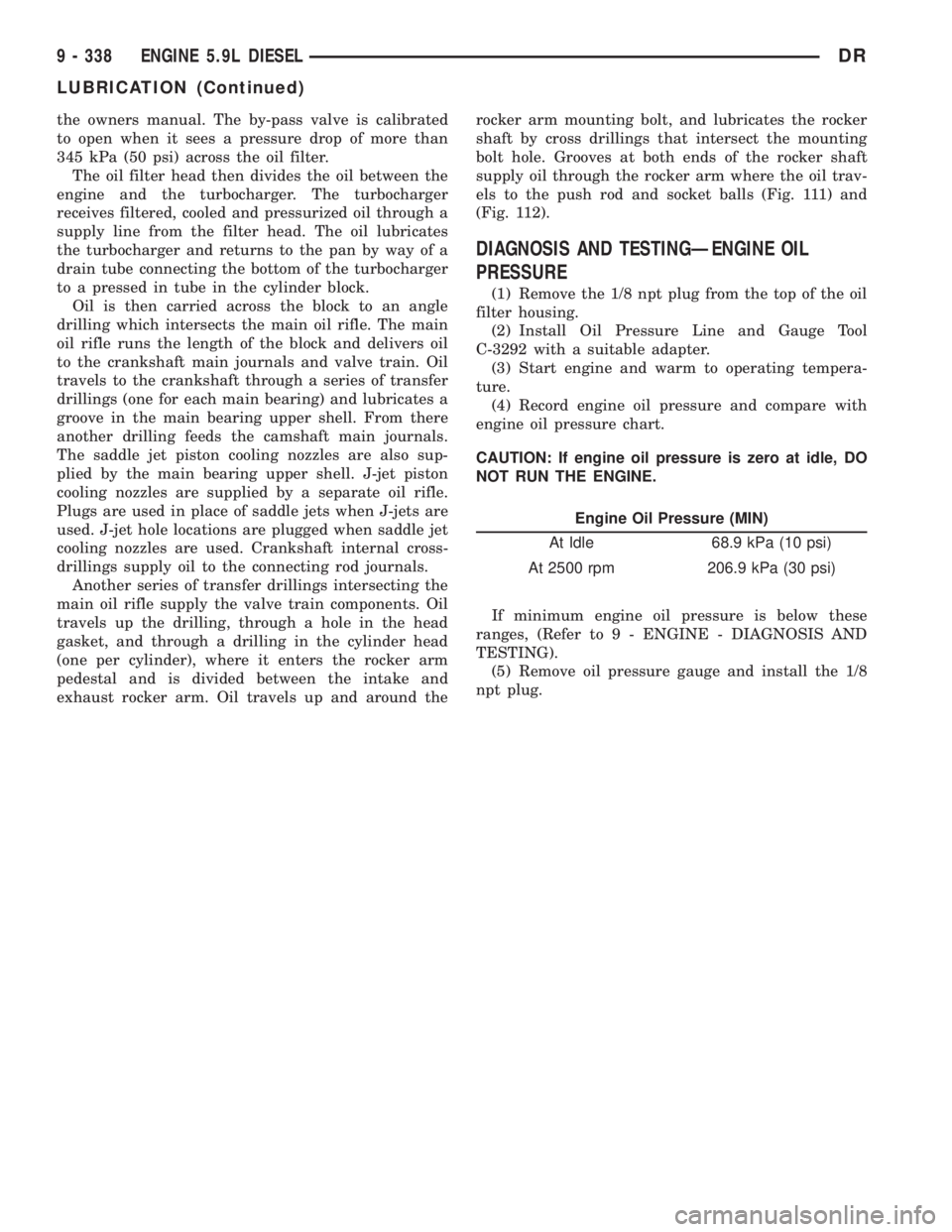
Engine Oil Pressure (MIN)
At Idle 68.9 kPa (10 psi)
At 2500 rpm 206.9 kPa (30 psi)
If minimum engine oil pressure is below these
ranges, (Refer to 9 - ENGINE - DIAGNOSIS AND
TESTING).
(5) Remove oil pressure gauge and install the 1/8
npt plug.
9 - 338 ENGINE 5.9L DIESELDR
LUBRICATION (Continued)
Page 1797 of 2895
DIAGNOSIS AND TESTING - POWER STEERING
FLOW AND PRESSURE
The following procedure is used to test the opera-
tion of the power steering system on the vehicle. This
test will provide the gallons per minute (GPM) or
flow rate of the power steering pump along with the
maximum relief pressure. Perform test any time a
power steering system problem is present. This test
will determine if the power steering pump or power
steering gear is not functioning properly. The follow-
ing pressure and flow test is performed using Power
Steering Analyzer Tool kit 6815 and (Fig. 2) Adapter
Kit 6893.
FLOW AND PRESSURE TEST
(1) Check the power steering belt to ensure it is in
good condition and adjusted properly.
(2) Connect pressure gauge hose from the Power
Steering Analyzer to adapter 6826.
(3) Connect tube 6825A to Power Steering Ana-
lyzer test valve end.
(4) Disconnect the high pressure hose from the
power steering pump.
(5) Connect the tube 6825A to the pump fitting.
(6) Connect the power steering hose from the
steering gear to the adapter 6826.
(7) Open the test valve completely.
(8) Start engine and let idle long enough to circu-
late power steering fluid through flow/pressure test
gauge and to get air out of the fluid. Then shut off
engine.(9) Check fluid level, add fluid as necessary. Start
engine again and let idle.
(10) Gauge should read below 862 kPa (125 psi), if
above, inspect the hoses for restrictions and repair as
necessary. The initial pressure reading should be in
the range of 345-552 kPa (50-80 psi).
(11) Increase the engine speed to 1500 RPM and
read the flow meter. If the flow rate (GPM) is below
specification, (refer to pump specification chart for
GPM) the pump should be replaced.
CAUTION: The following test procedure involves
testing maximum pump pressure output and flow
control valve operation. Do not leave valve closed
for more than three seconds as the pump could be
damaged.
(12) Close valve fully three times and record high-
est pressure indicated each time.All three read-
ings must be above specifications and within
345 kPa (50 psi) of each other.
²Pressures above specifications but not within
345 kPa (50 psi) of each other, replace pump.
²Pressures within 345 kPa (50 psi) of each other
but below specifications, replace pump.
(13) Open the test valve and turn the steering
wheel to the extreme left and right positions three
times against the stops. Record the highest pressure
reading at each position. Compare readings to the
pump specifications chart. If pressures readings are
not within 50 psi of each other, the gear is leaking
internally and must be replaced.
CAUTION: Do not force the pump to operate against
the stops for more than 2 to 3 seconds at a time
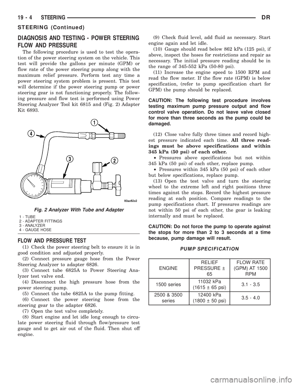
because, pump damage will result.PUMP SPECIFICATION
ENGINERELIEF
PRESSURE
65FLOW RATE
(GPM) AT 1500
RPM
1500 series11032 kPa
(1615 65 psi)3.1 - 3.5
2500 & 3500
series12400 kPa
(1800 50 psi)3.5 - 4.0
Fig. 2 Analyzer With Tube and Adapter
1 - TUBE
2 - ADAPTER FITTINGS
3 - ANALYZER
4 - GAUGE HOSE
19 - 4 STEERINGDR
STEERING (Continued)
Page 2572 of 2895
center caps for more information refer to Owner's
Manual.
The tires on both wheels must be completely raised
off the ground when tightening the lug nuts. This
will ensure correct wheel centering and maximum
wheel clamping.
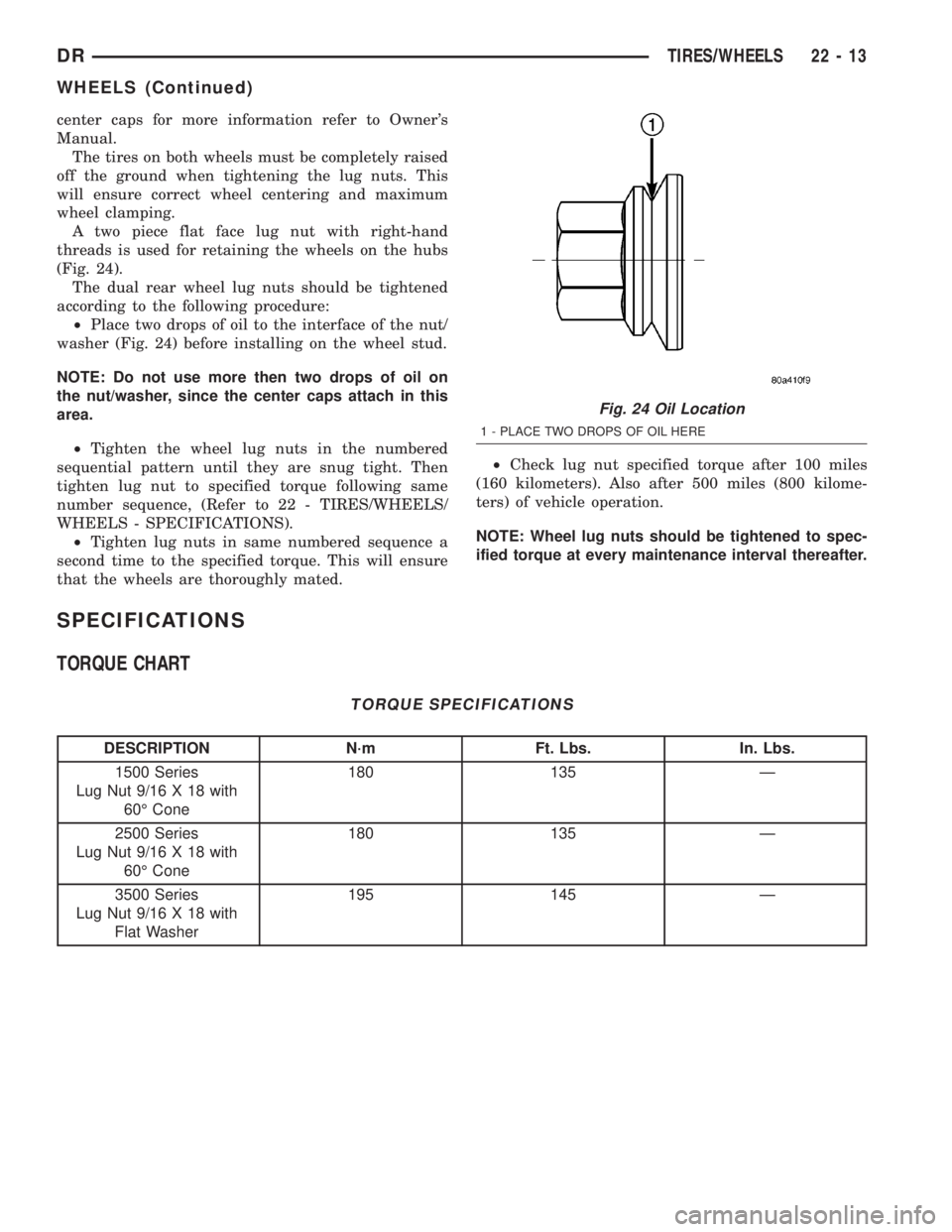
A two piece flat face lug nut with right-hand
threads is used for retaining the wheels on the hubs
(Fig. 24).
The dual rear wheel lug nuts should be tightened
according to the following procedure:
²Place two drops of oil to the interface of the nut/
washer (Fig. 24) before installing on the wheel stud.
NOTE: Do not use more then two drops of oil on
the nut/washer, since the center caps attach in this
area.
²Tighten the wheel lug nuts in the numbered
sequential pattern until they are snug tight. Then
tighten lug nut to specified torque following same
number sequence, (Refer to 22 - TIRES/WHEELS/
WHEELS - SPECIFICATIONS).
²Tighten lug nuts in same numbered sequence a
second time to the specified torque. This will ensure
that the wheels are thoroughly mated.²Check lug nut specified torque after 100 miles
(160 kilometers). Also after 500 miles (800 kilome-
ters) of vehicle operation.
NOTE: Wheel lug nuts should be tightened to spec-
ified torque at every maintenance interval thereafter.
SPECIFICATIONS
TORQUE CHART
TORQUE SPECIFICATIONS
DESCRIPTION N´m Ft. Lbs. In. Lbs.
1500 Series
Lug Nut 9/16 X 18 with
60É Cone180 135 Ð
2500 Series
Lug Nut 9/16 X 18 with
60É Cone180 135 Ð
3500 Series
Lug Nut 9/16 X 18 with
Flat Washer195 145 Ð
Fig. 24 Oil Location
1 - PLACE TWO DROPS OF OIL HERE
DRTIRES/WHEELS 22 - 13
WHEELS (Continued)
Page 2573 of 2895
STUDS
REMOVAL
(1) Raise and support the vehicle.
(2) Remove the wheel and tire assembly.
(3) Remove the brake caliper, caliper adapter and
rotor, (Refer to 5 - BRAKES/HYDRAULIC/MECHAN-
ICAL/ROTORS - REMOVAL).
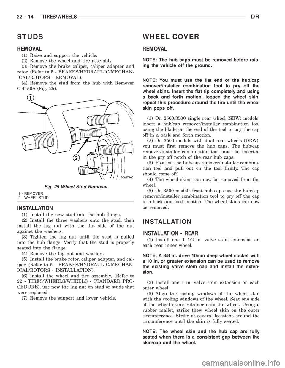
(4) Remove the stud from the hub with Remover
C-4150A (Fig. 25).
INSTALLATION
(1) Install the new stud into the hub flange.
(2) Install the three washers onto the stud, then
install the lug nut with the flat side of the nut
against the washers.
(3) Tighten the lug nut until the stud is pulled
into the hub flange. Verify that the stud is properly
seated into the flange.
(4) Remove the lug nut and washers.
(5) Install the brake rotor, caliper adapter, and cal-
iper, (Refer to 5 - BRAKES/HYDRAULIC/MECHAN-
ICAL/ROTORS - INSTALLATION).
(6) Install the wheel and tire assembly, (Refer to
22 - TIRES/WHEELS/WHEELS - STANDARD PRO-
CEDURE), use new the lug nut on stud or studs that
were replaced.
(7) Remove the support and lower vehicle.
WHEEL COVER
REMOVAL
NOTE: The hub caps must be removed before rais-
ing the vehicle off the ground.
NOTE: You must use the flat end of the hub/cap
remover/installer combination tool to pry off the
wheel skins. Insert the flat tip completely and using
a back and forth motion, loosen the wheel skin.
repeat this procedure around the tire until the wheel
skin pops off.
(1) On 2500/3500 single rear wheel (SRW) models,
insert a hub/cap remover/installer combination tool
using the blade on the end of the tool to pry the cap
off in a back and forth motion.
(2) On 3500 models with dual rear wheels (DRW),
you must first remove the hub caps. The hub/cap
remover/installer combination tool must be inserted
in the pry off notch of the rear hub caps.
(3) Position the hub/cap remover/installer combina-
tion tool and pull out on the tool firmly. The cap
should come off.
(4) The wheel skins can now be removed from the
wheel.
(5) On 3500 models front hub caps use the hub/cap
remover/installer combination tool to pry off the cap
in a back and forth motion. The wheel skins can now
be removed.
INSTALLATION
INSTALLATION - REAR
(1) Install one 1 1/2 in. valve stem extension on
each rear inner wheel.
NOTE: A 3/8 in. drive 10mm deep wheel socket with
a 10 in. or greater extension can be used to remove
the existing valve stem cap and install the exten-
sion.
(2) Install one 1 in. valve stem extension on each
outer wheel.
(3) Align the cooling windows of the wheel skin
with the cooling windows of the wheel. Seat one side
of the wheel skin's retainer onto the wheel. Using a
rubber mallet, strike thew wheel skin on the outer
circumference. Strike at several locations around the
circumference until the skin is fully seated.
NOTE: The wheel skin and the hub cap are fully
seated when there is a consistent gap between the
skin/cap and the wheel.
Fig. 25 Wheel Stud Removal
1 - REMOVER
2 - WHEEL STUD
22 - 14 TIRES/WHEELSDR