5 speed manual transmission DODGE RAM 2003 Service Repair Manual
[x] Cancel search | Manufacturer: DODGE, Model Year: 2003, Model line: RAM, Model: DODGE RAM 2003Pages: 2895, PDF Size: 83.15 MB
Page 1 of 2895
GROUP TAB LOCATOR
Introduction
0Lubrication & Maintenance
2Suspension
3Differential & Driveline
5Brakes
6Clutch
7Cooling
8AAudio
8BChime/Buzzer
8EElectronic Control Modules
8FEngine Systems
8GHeated Systems
8HHorn
8IIgnition Control
8JInstrument Cluster
8LLamps
8MMessage Systems
8NPower Systems
8ORestraints
8PSpeed Control
8QVehicle Theft Security
8RWipers/Washers
8WWiring
9Engine
11Exhaust System
13Frame & Bumpers
14Fuel System
19Steering
21Transmission and Transfer Case
22Tires/Wheels
23Body
24Heating & Air Conditioning
25Emissions Control
Component and System Index
Service Manual Comment Forms (Rear of Manual)
Page 5 of 2895
BODY CODE PLATE
DESCRIPTION
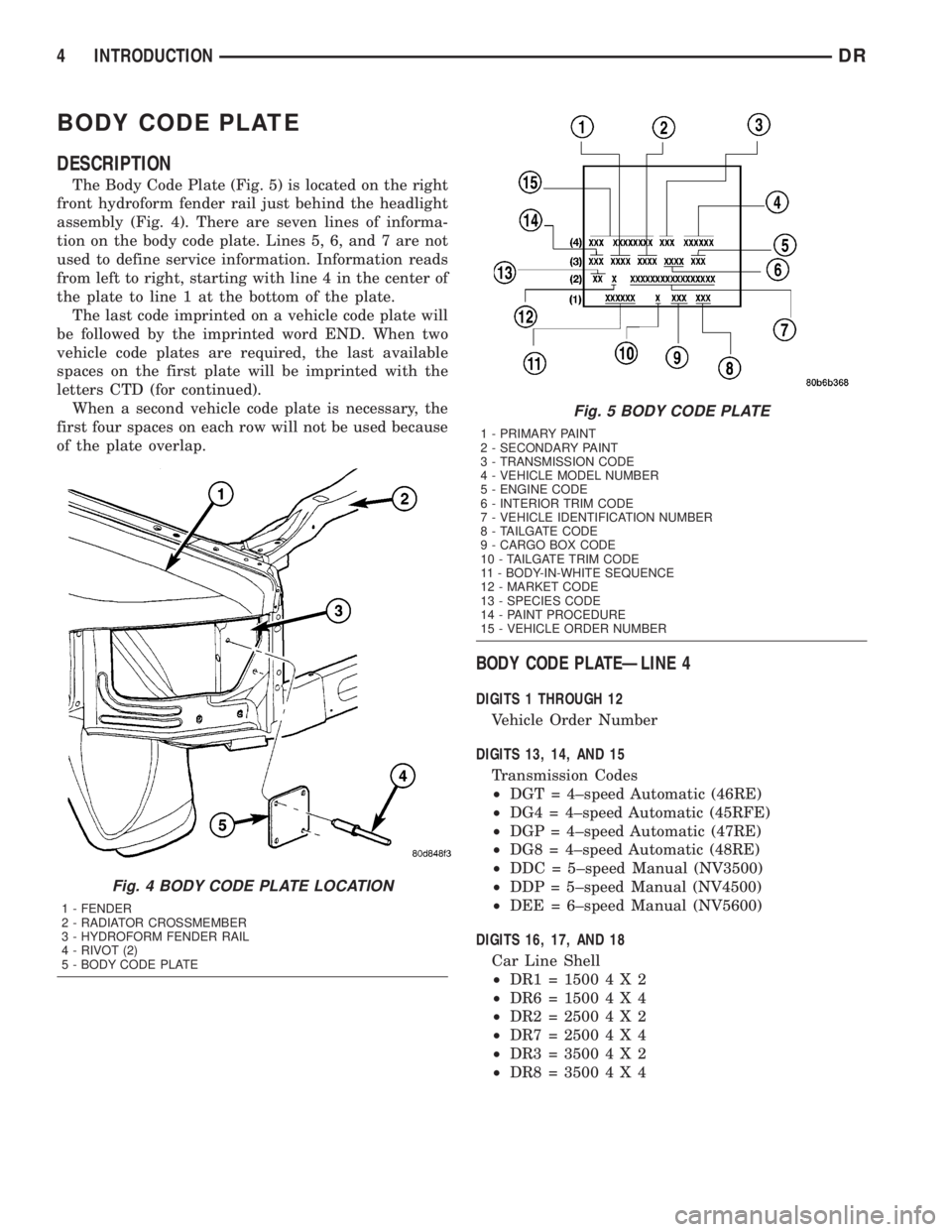
The Body Code Plate (Fig. 5) is located on the right
front hydroform fender rail just behind the headlight
assembly (Fig. 4). There are seven lines of informa-
tion on the body code plate. Lines 5, 6, and 7 are not
used to define service information. Information reads
from left to right, starting with line 4 in the center of
the plate to line 1 at the bottom of the plate.
The last code imprinted on a vehicle code plate will
be followed by the imprinted word END. When two
vehicle code plates are required, the last available
spaces on the first plate will be imprinted with the
letters CTD (for continued).
When a second vehicle code plate is necessary, the
first four spaces on each row will not be used because
of the plate overlap.
BODY CODE PLATEÐLINE 4
DIGITS 1 THROUGH 12
Vehicle Order Number
DIGITS 13, 14, AND 15
Transmission Codes
²DGT = 4±speed Automatic (46RE)
²DG4 = 4±speed Automatic (45RFE)
²DGP = 4±speed Automatic (47RE)
²DG8 = 4±speed Automatic (48RE)
²DDC = 5±speed Manual (NV3500)
²DDP = 5±speed Manual (NV4500)
²DEE = 6±speed Manual (NV5600)
DIGITS 16, 17, AND 18
Car Line Shell
²DR1=15004X2
²DR6=15004X4
²DR2=25004X2
²DR7=25004X4
²DR3=35004X2
²DR8=35004X4
Fig. 4 BODY CODE PLATE LOCATION
1 - FENDER
2 - RADIATOR CROSSMEMBER
3 - HYDROFORM FENDER RAIL
4 - RIVOT (2)
5 - BODY CODE PLATE
Fig. 5 BODY CODE PLATE
1 - PRIMARY PAINT
2 - SECONDARY PAINT
3 - TRANSMISSION CODE
4 - VEHICLE MODEL NUMBER
5 - ENGINE CODE
6 - INTERIOR TRIM CODE
7 - VEHICLE IDENTIFICATION NUMBER
8 - TAILGATE CODE
9 - CARGO BOX CODE
10 - TAILGATE TRIM CODE
11 - BODY-IN-WHITE SEQUENCE
12 - MARKET CODE
13 - SPECIES CODE
14 - PAINT PROCEDURE
15 - VEHICLE ORDER NUMBER
4 INTRODUCTIONDR
Page 19 of 2895
MAINTENANCE SCHEDULES
DESCRIPTION
Maintenance Schedule Information not included in
this section, is located in the appropriate Owner's
Manual.
There are two maintenance schedules that show
therequiredservice for your vehicle.
First is ScheduleªBº. It is for vehicles that are
operated under the conditions that are listed below
and at the beginning of the schedule.
²Day or night temperatures are below 0É C (32É
F).
²Stop and go driving.
²Extensive engine idling.
²Driving in dusty conditions.
²Short trips of less than 16 km (10 miles).
²More than 50% of your driving is at sustained
high speeds during hot weather, above 32É C (90É F).
²Trailer towing.
²Taxi, police, or delivery service (commercial ser-
vice).
²Off-road or desert operation.
²If equipped for and operating with E-85
(ethanol) fuel.
NOTE: Most vehicles are operated under the condi-
tions listed for Schedule(B(.
Second is ScheduleªAº. It is for vehicles that are
not operated under any of the conditions listed under
Schedule9B9.
Use the schedule that best describes your driving
conditions. Where time and mileage are listed, follow
the interval that occurs first.
CAUTION: Failure to perform the required mainte-
nance items may result in damage to the vehicle.
At Each Stop for Fuel
²Check the engine oil level about 5 minutes after
a fully warmed engine is shut off. Checking the oil
level while the vehicle is on level ground will
improve the accuracy of the oil level reading. Add oil
only when the level is at or below the ADD or MIN
mark.
²Check the windshield washer solvent and add if
required.
Once a Month
²Check tire pressure and look for unusual wear
or damage.
²Inspect the battery and clean and tighten the
terminals as required.
²Check the fluid levels of coolant reservoir, brake
master cylinder, power steering and transmission
and add as needed.
²Check all lights and all other electrical items for
correct operation.
At Each Oil Change
²Change the engine oil filter.
²Inspect the exhaust system.
²Inspect the brake hoses.
²Inspect the CV joints (if equipped) and front sus-
pension components.
²Check the automatic transmission fluid level.
²Check the manual transmission fluid level.
²Check the coolant level, hoses, and clamps.
²Rotate the tires at each oil change interval
shown on Schedule ªAº 10 000 km (6,000 miles) or
every other interval shown on Schedule ªBº 10 000
km (6,000 miles).
Schedule ªBº
Follow schedule ªBº if you usually operate your
vehicle under one or more of the following conditions.
²Day or night temperatures are below 0É C (32É
F).
²Stop and go driving.
²Extensive engine idling.
²Driving in dusty conditions.
²Short trips of less than 16 km (10 miles).
²More than 50% of your driving is at sustained
high speeds during hot weather, above 32É C (90É F).
²Trailer towing.
²Taxi, police, or delivery service (commercial ser-
vice).
²Off-road or desert operation.
²If equipped for and operating with E-85
(ethanol) fuel.
0 - 6 LUBRICATION & MAINTENANCEDR
Page 397 of 2895
²Diagnostic Requests
²Manual Transmission and Brake Applied
²PRNDL
²Ignition Status
²ABS Messages
Once the TCCM determines that a requested shift
is allowed, it actuates the bi-directional shift motor
as necessary to achieve the desired transfer case
operating mode. The TCCM also monitors the mode
sensor while controlling the shift motor to determine
the status of the shift attempt.
Several items can cause the requested shift not to
be completed. If the TCCM has recognized a fault
(DTC) of some variety, it will begin operation in one
of four Functionality Levels. These levels are:
²Level Zero- Normal Operation.
²Level One- Only Mode Shifts Are Allowed.
²Level Two- Only Mode Shifts and Shifts Into
LOW Are Allowed (No Neutral Shifts Are Allowed).
²Level Three- No Shifts Are Allowed
The TCCM can also be operating in one of three
possible power modes. These power modes are:
²Full Power Modeis the normal operational
mode of the module. This mode is achieved by normal
PCI bus traffic being present and the ignition being
in the RUN position.
²Reduced Power Modewill be entered when
the ignition has been powered off. In this state, the
module will shut down power supplied to external
devices, and to electronic interface inputs and out-
puts. From this state the module can enter either
Sleep Mode or Full Power Mode. To enter this mode,
the module must receive an ignition message denot-
ing that the ignition is off, or not receive any mes-
sages for 5 0.5 seconds. To exit this mode, themodule must receive one ignition message that
denotes that the ignition is in the RUN position.
²Sleep Modewill be entered, from the Reduced
Power Mode, when no PCI traffic has been sensed for
20 1 seconds. If during Sleep Mode the module
detects PCI bus traffic, it will revert to the Reduced
Power mode while monitoring for ignition messages.
It will remain in this state as long as there is traffic
other than run or start messages, and will return to
Sleep mode if the bus goes without traffic for 20 1
seconds.
SHIFT REQUIREMENTS
If the TCCM is in full power mode and at function-
ality level zero, it uses the following criteria to deter-
mine if a shift is allowed.
If any of the driver controllable conditions are not
met once the shift request is recognized, the TCCM
will solidly illuminate the source position's LED and
flash the desired position's LED for all shifts except
NEUTRAL. The NEUTRAL shift LED strategy will
be discussed later.
Mode shiftswill be allowed regardless of trans-
mission gear or vehicle speed, whenever the following
conditions are met:
²Front and rear wheel speed are within 21 km/hr
(13 mph).
²A change in the Selector switch state indicates
that a mode shift has been requested.
²A valid mode sensor signal is being sensed by
the TCCM.
²Proper transmit/receive messages are occurring
on the PCI bus.
²Ignition key switch is in the RUN position.
Range shiftswill be allowed only if all of the fol-
lowing conditions are met:
²Front and rear wheel speed are within 21 km/hr
(13 mph).
²A change in the Selector Switch state indicating
a range shift has been requested.
²Transmission in NEUTRAL signal must be rec-
ognized for at least 1.5 seconds 100 msec. (Automat-
ic transmissions only)
²Proper transmit/receive messages are occurring
on the PCI bus.
²Clutch signal is recognized for 500 msec 50
msec (Manual transmissions only).
²Vehicle speed is less than or equal to 4.8 km/hr
(3 miles per hour).
²Ignition key switch is in the RUN position.
²A valid mode sensor signal is being sensed by
the TCCM.
Ashift into transfer case Neutralwill be
allowed only if all of the following conditions are met:
²Front and rear wheel speed are within 21 km/hr
(13 mph).
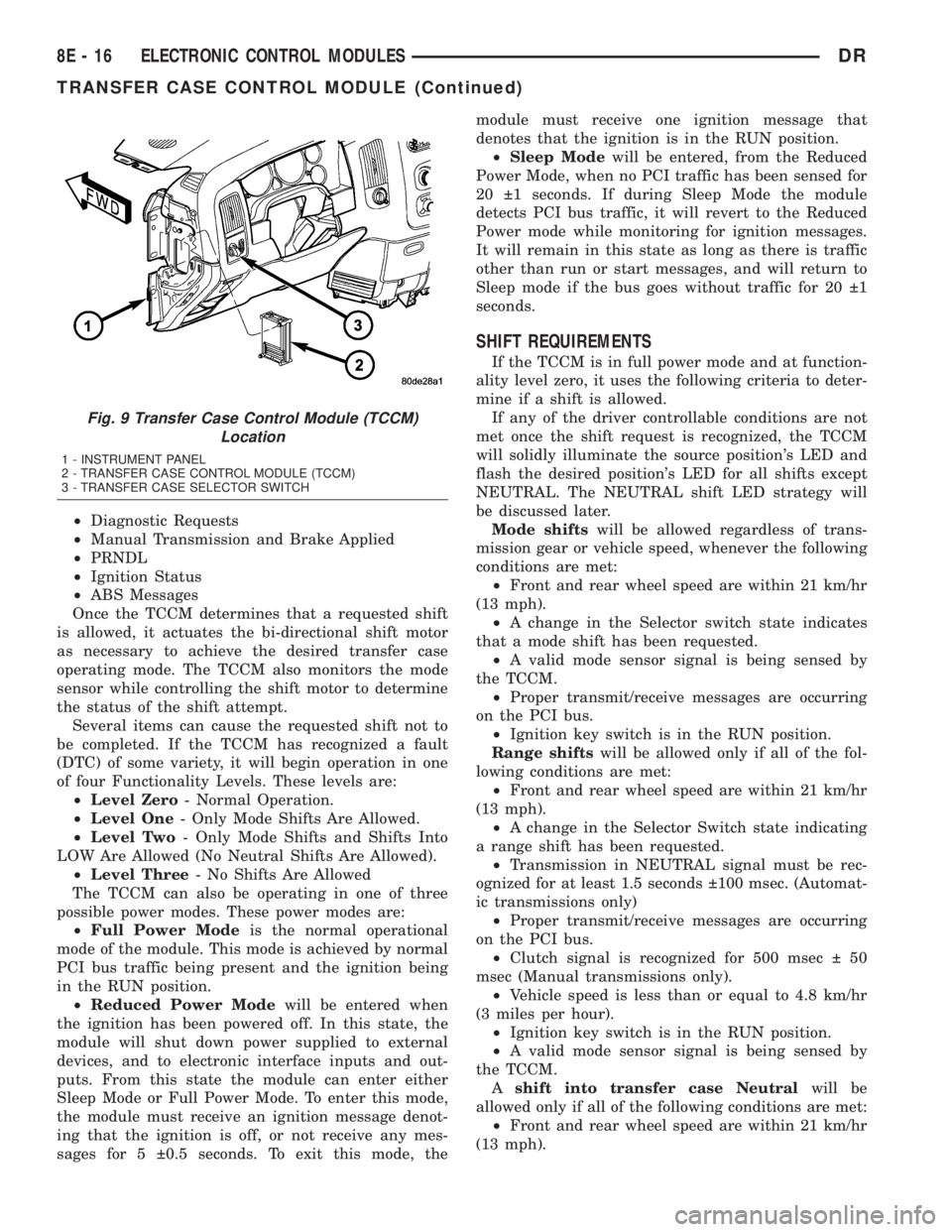
Fig. 9 Transfer Case Control Module (TCCM)
Location
1 - INSTRUMENT PANEL
2 - TRANSFER CASE CONTROL MODULE (TCCM)
3 - TRANSFER CASE SELECTOR SWITCH
8E - 16 ELECTRONIC CONTROL MODULESDR
TRANSFER CASE CONTROL MODULE (Continued)
Page 402 of 2895
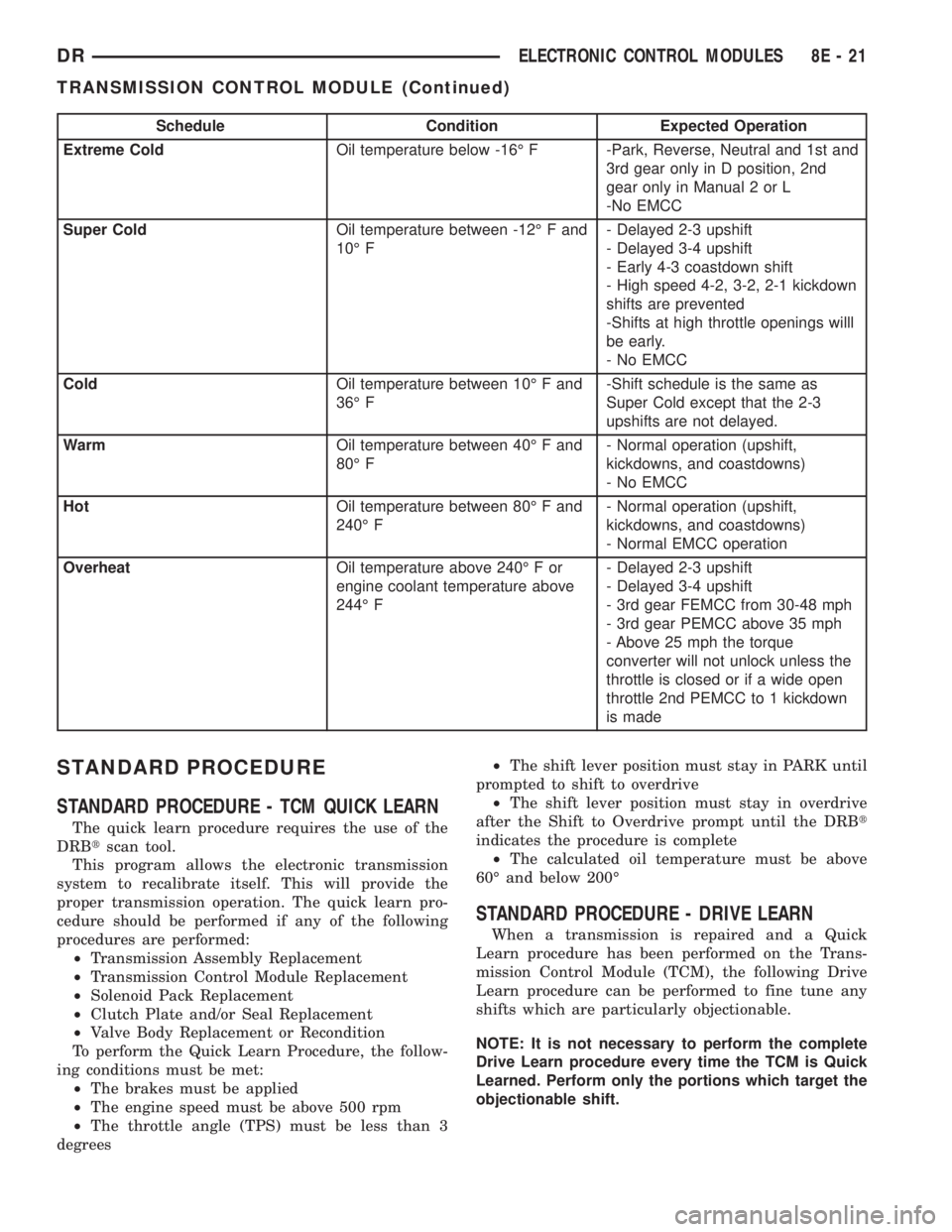
Schedule Condition Expected Operation
Extreme ColdOil temperature below -16É F -Park, Reverse, Neutral and 1st and
3rd gear only in D position, 2nd
gear only in Manual 2 or L
-No EMCC
Super ColdOil temperature between -12É F and
10É F- Delayed 2-3 upshift
- Delayed 3-4 upshift
- Early 4-3 coastdown shift
- High speed 4-2, 3-2, 2-1 kickdown
shifts are prevented
-Shifts at high throttle openings willl
be early.
- No EMCC
ColdOil temperature between 10É F and
36É F-Shift schedule is the same as
Super Cold except that the 2-3
upshifts are not delayed.
WarmOil temperature between 40É F and
80É F- Normal operation (upshift,
kickdowns, and coastdowns)
- No EMCC
HotOil temperature between 80É F and
240É F- Normal operation (upshift,
kickdowns, and coastdowns)
- Normal EMCC operation
OverheatOil temperature above 240É F or
engine coolant temperature above
244É F- Delayed 2-3 upshift
- Delayed 3-4 upshift
- 3rd gear FEMCC from 30-48 mph
- 3rd gear PEMCC above 35 mph
- Above 25 mph the torque
converter will not unlock unless the
throttle is closed or if a wide open
throttle 2nd PEMCC to 1 kickdown
is made
STANDARD PROCEDURE
STANDARD PROCEDURE - TCM QUICK LEARN
The quick learn procedure requires the use of the
DRBtscan tool.
This program allows the electronic transmission
system to recalibrate itself. This will provide the
proper transmission operation. The quick learn pro-
cedure should be performed if any of the following
procedures are performed:
²Transmission Assembly Replacement
²Transmission Control Module Replacement
²Solenoid Pack Replacement
²Clutch Plate and/or Seal Replacement
²Valve Body Replacement or Recondition
To perform the Quick Learn Procedure, the follow-
ing conditions must be met:
²The brakes must be applied
²The engine speed must be above 500 rpm
²The throttle angle (TPS) must be less than 3
degrees²The shift lever position must stay in PARK until
prompted to shift to overdrive
²The shift lever position must stay in overdrive
after the Shift to Overdrive prompt until the DRBt
indicates the procedure is complete
²The calculated oil temperature must be above
60É and below 200É
STANDARD PROCEDURE - DRIVE LEARN
When a transmission is repaired and a Quick
Learn procedure has been performed on the Trans-
mission Control Module (TCM), the following Drive
Learn procedure can be performed to fine tune any
shifts which are particularly objectionable.
NOTE: It is not necessary to perform the complete
Drive Learn procedure every time the TCM is Quick
Learned. Perform only the portions which target the
objectionable shift.
DRELECTRONIC CONTROL MODULES 8E - 21
TRANSMISSION CONTROL MODULE (Continued)
Page 404 of 2895
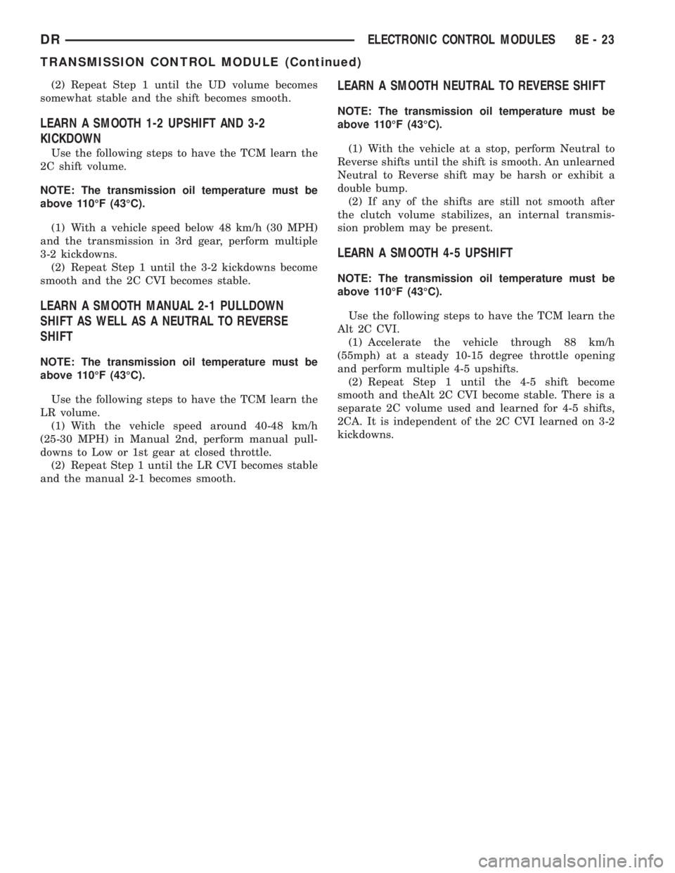
(2) Repeat Step 1 until the UD volume becomes
somewhat stable and the shift becomes smooth.
LEARN A SMOOTH 1-2 UPSHIFT AND 3-2
KICKDOWN
Use the following steps to have the TCM learn the
2C shift volume.
NOTE: The transmission oil temperature must be
above 110ÉF (43ÉC).
(1) With a vehicle speed below 48 km/h (30 MPH)
and the transmission in 3rd gear, perform multiple
3-2 kickdowns.
(2) Repeat Step 1 until the 3-2 kickdowns become
smooth and the 2C CVI becomes stable.
LEARN A SMOOTH MANUAL 2-1 PULLDOWN
SHIFT AS WELL AS A NEUTRAL TO REVERSE
SHIFT
NOTE: The transmission oil temperature must be
above 110ÉF (43ÉC).
Use the following steps to have the TCM learn the
LR volume.
(1) With the vehicle speed around 40-48 km/h
(25-30 MPH) in Manual 2nd, perform manual pull-
downs to Low or 1st gear at closed throttle.
(2) Repeat Step 1 until the LR CVI becomes stable
and the manual 2-1 becomes smooth.
LEARN A SMOOTH NEUTRAL TO REVERSE SHIFT
NOTE: The transmission oil temperature must be
above 110ÉF (43ÉC).
(1) With the vehicle at a stop, perform Neutral to
Reverse shifts until the shift is smooth. An unlearned
Neutral to Reverse shift may be harsh or exhibit a
double bump.
(2) If any of the shifts are still not smooth after
the clutch volume stabilizes, an internal transmis-
sion problem may be present.
LEARN A SMOOTH 4-5 UPSHIFT
NOTE: The transmission oil temperature must be
above 110ÉF (43ÉC).
Use the following steps to have the TCM learn the
Alt 2C CVI.
(1) Accelerate the vehicle through 88 km/h
(55mph) at a steady 10-15 degree throttle opening
and perform multiple 4-5 upshifts.
(2) Repeat Step 1 until the 4-5 shift become
smooth and theAlt 2C CVI become stable. There is a
separate 2C volume used and learned for 4-5 shifts,
2CA. It is independent of the 2C CVI learned on 3-2
kickdowns.
DRELECTRONIC CONTROL MODULES 8E - 23
TRANSMISSION CONTROL MODULE (Continued)
Page 438 of 2895
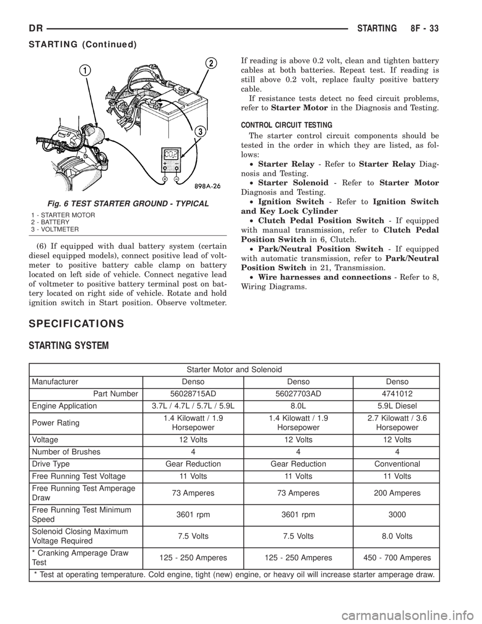
(6) If equipped with dual battery system (certain
diesel equipped models), connect positive lead of volt-
meter to positive battery cable clamp on battery
located on left side of vehicle. Connect negative lead
of voltmeter to positive battery terminal post on bat-
tery located on right side of vehicle. Rotate and hold
ignition switch in Start position. Observe voltmeter.If reading is above 0.2 volt, clean and tighten battery
cables at both batteries. Repeat test. If reading is
still above 0.2 volt, replace faulty positive battery
cable.
If resistance tests detect no feed circuit problems,
refer toStarter Motorin the Diagnosis and Testing.
CONTROL CIRCUIT TESTING
The starter control circuit components should be
tested in the order in which they are listed, as fol-
lows:
²Starter Relay- Refer toStarter RelayDiag-
nosis and Testing.
²Starter Solenoid- Refer toStarter Motor
Diagnosis and Testing.
²Ignition Switch- Refer toIgnition Switch
and Key Lock Cylinder
²Clutch Pedal Position Switch- If equipped
with manual transmission, refer toClutch Pedal
Position Switchin 6, Clutch.
²Park/Neutral Position Switch- If equipped
with automatic transmission, refer toPark/Neutral
Position Switchin 21, Transmission.
²Wire harnesses and connections- Refer to 8,
Wiring Diagrams.
SPECIFICATIONS
STARTING SYSTEM
Starter Motor and Solenoid
Manufacturer Denso Denso Denso
Part Number 56028715AD 56027703AD 4741012
Engine Application 3.7L / 4.7L / 5.7L / 5.9L 8.0L 5.9L Diesel
Power Rating1.4 Kilowatt / 1.9
Horsepower1.4 Kilowatt / 1.9
Horsepower2.7 Kilowatt / 3.6
Horsepower
Voltage 12 Volts 12 Volts 12 Volts
Number of Brushes 4 4 4
Drive Type Gear Reduction Gear Reduction Conventional
Free Running Test Voltage 11 Volts 11 Volts 11 Volts
Free Running Test Amperage
Draw73 Amperes 73 Amperes 200 Amperes
Free Running Test Minimum
Speed3601 rpm 3601 rpm 3000
Solenoid Closing Maximum
Voltage Required7.5 Volts 7.5 Volts 8.0 Volts
* Cranking Amperage Draw
Test125 - 250 Amperes 125 - 250 Amperes 450 - 700 Amperes
* Test at operating temperature. Cold engine, tight (new) engine, or heavy oil will increase starter amperage draw.
Fig. 6 TEST STARTER GROUND - TYPICAL
1 - STARTER MOTOR
2 - BATTERY
3 - VOLTMETER
DRSTARTING 8F - 33
STARTING (Continued)
Page 498 of 2895
the vehicle speed remains greater than about twenty-
four kilometers-per-hour (fifteen miles-per-hour).
²Vacuum Fluorescent Display Synchroniza-
tion- The EMIC transmits electronic panel lamp
dimming level messages which allows all other elec-
tronic modules on the PCI data bus with Vacuum
Fluorescent Display (VFD) units to coordinate their
illumination intensity with that of the EMIC VFD
units.
²Vehicle Theft Security System- The EMIC
monitors inputs from the door cylinder lock switch-
(es), the door ajar switches, the ignition switch, and
the Remote Keyless Entry (RKE) receiver module,
then provides electronic horn and lighting request
messages to the Front Control Module (FCM) located
on the Integrated Power Module (IPM) for the appro-
priate VTSS alarm output features.
²Wiper/Washer System Control- The EMIC
provides electronic wiper and/or washer request mes-
sages to the Front Control Module (FCM) located on
the Integrated Power Module (IPM) for the appropri-
ate wiper and washer system features. (Refer to 8 -
ELECTRICAL/WIPERS/WASHERS - DESCRIP-
TION).
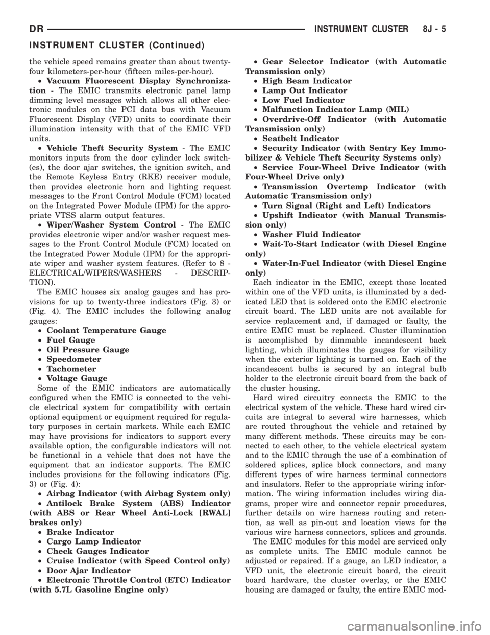
The EMIC houses six analog gauges and has pro-
visions for up to twenty-three indicators (Fig. 3) or
(Fig. 4). The EMIC includes the following analog
gauges:
²Coolant Temperature Gauge
²Fuel Gauge
²Oil Pressure Gauge
²Speedometer
²Tachometer
²Voltage Gauge
Some of the EMIC indicators are automatically
configured when the EMIC is connected to the vehi-
cle electrical system for compatibility with certain
optional equipment or equipment required for regula-
tory purposes in certain markets. While each EMIC
may have provisions for indicators to support every
available option, the configurable indicators will not
be functional in a vehicle that does not have the
equipment that an indicator supports. The EMIC
includes provisions for the following indicators (Fig.
3) or (Fig. 4):
²Airbag Indicator (with Airbag System only)
²Antilock Brake System (ABS) Indicator
(with ABS or Rear Wheel Anti-Lock [RWAL]
brakes only)
²Brake Indicator
²Cargo Lamp Indicator
²Check Gauges Indicator
²Cruise Indicator (with Speed Control only)
²Door Ajar Indicator
²Electronic Throttle Control (ETC) Indicator
(with 5.7L Gasoline Engine only)²Gear Selector Indicator (with Automatic
Transmission only)
²High Beam Indicator
²Lamp Out Indicator
²Low Fuel Indicator
²Malfunction Indicator Lamp (MIL)
²Overdrive-Off Indicator (with Automatic
Transmission only)
²Seatbelt Indicator
²Security Indicator (with Sentry Key Immo-
bilizer & Vehicle Theft Security Systems only)
²Service Four-Wheel Drive Indicator (with
Four-Wheel Drive only)
²Transmission Overtemp Indicator (with
Automatic Transmission only)
²Turn Signal (Right and Left) Indicators
²Upshift Indicator (with Manual Transmis-
sion only)
²Washer Fluid Indicator
²Wait-To-Start Indicator (with Diesel Engine
only)
²Water-In-Fuel Indicator (with Diesel Engine
only)
Each indicator in the EMIC, except those located
within one of the VFD units, is illuminated by a ded-
icated LED that is soldered onto the EMIC electronic
circuit board. The LED units are not available for
service replacement and, if damaged or faulty, the
entire EMIC must be replaced. Cluster illumination
is accomplished by dimmable incandescent back
lighting, which illuminates the gauges for visibility
when the exterior lighting is turned on. Each of the
incandescent bulbs is secured by an integral bulb
holder to the electronic circuit board from the back of
the cluster housing.
Hard wired circuitry connects the EMIC to the
electrical system of the vehicle. These hard wired cir-
cuits are integral to several wire harnesses, which
are routed throughout the vehicle and retained by
many different methods. These circuits may be con-
nected to each other, to the vehicle electrical system
and to the EMIC through the use of a combination of
soldered splices, splice block connectors, and many
different types of wire harness terminal connectors
and insulators. Refer to the appropriate wiring infor-
mation. The wiring information includes wiring dia-
grams, proper wire and connector repair procedures,
further details on wire harness routing and reten-
tion, as well as pin-out and location views for the
various wire harness connectors, splices and grounds.
The EMIC modules for this model are serviced only
as complete units. The EMIC module cannot be
adjusted or repaired. If a gauge, an LED indicator, a
VFD unit, the electronic circuit board, the circuit
board hardware, the cluster overlay, or the EMIC
housing are damaged or faulty, the entire EMIC mod-
DRINSTRUMENT CLUSTER 8J - 5
INSTRUMENT CLUSTER (Continued)
Page 533 of 2895
sages to the Front Control Module (FCM) over the
Programmable Communications Interface (PCI) data
bus and flashes the turn signal indicators on and off
accordingly. For further diagnosis of the turn signal
indicators or the instrument cluster circuitry that
controls the indicators, (Refer to 8 - ELECTRICAL/
INSTRUMENT CLUSTER - DIAGNOSIS AND
TESTING). For proper diagnosis of the turn signal
and hazard warning system, the multi-function
switch, the FCM, the PCI data bus, or the electronic
message inputs to the instrument cluster that control
the turn signal indicators, a DRBIIItscan tool is
required. Refer to the appropriate diagnostic infor-
mation.
UPSHIFT INDICATOR
DESCRIPTION
An upshift indicator is standard equipment on all
instrument clusters. However, on vehicles not
equipped with a manual transmission, this indicator
is electronically disabled. The upshift indicator con-
sists of an upward pointed arrow icon, which appears
on the right side of the electronic gear selector indi-
cator Vacuum Fluorescent Display (VFD) unit. The
VFD is soldered onto the cluster electronic circuit
board and is visible through a window with a smoked
clear lens located on the lower edge of the speedom-
eter gauge dial face of the cluster overlay. The dark
lens over the VFD prevents the indicator from being
clearly visible when it is not illuminated. The icon
appears in a blue-green color and at the same light-
ing level as the odometer/trip odometer information
when it is illuminated by the instrument cluster elec-
tronic circuit board. The upshift indicator is serviced
as a unit with the instrument cluster.
OPERATION
The upshift indicator gives an indication to the
vehicle operator when the manual transmission
should be shifted to the next highest gear in order to
achieve the best fuel economy. This indicator is con-
trolled by the instrument cluster circuit board based
upon cluster programming and electronic messages
received by the cluster from the Powertrain Control
Module (PCM) on vehicles with a gasoline engine, or
from the Engine Control Module (ECM) on vehicles
with a diesel engine over the Programmable Commu-
nications Interface (PCI) data bus. The upshift indi-
cator is completely controlled by the instrument
cluster logic circuit, and that logic will only allow
this indicator to operate when the instrument cluster
receives a battery current input on the fused ignition
switch output (run-start) circuit. Therefore, the indi-
cator will always be off when the ignition switch is inany position except On or Start. The indicator only
illuminates when it is switched to ground by the
instrument cluster circuitry. The instrument cluster
will turn on the upshift indicator for the following
reasons:
²Upshift Lamp-On Message- Each time the
cluster receives an upshift lamp-on message from the
PCM or ECM indicating the engine speed and load
conditions are right for a transmission upshift to
occur, the upshift indicator is illuminated. The indi-
cator remains illuminated until the cluster receives
an upshift lamp-off message from the PCM or ECM,
or until the ignition switch is turned to the Off posi-
tion, whichever occurs first. The PCM or ECM will
normally send an upshift lamp-off message three to
five seconds after a lamp-on message, if an upshift is
not performed. The indicator will then remain off
until the vehicle stops accelerating and is brought
back into the range of indicator operation, or until
the transmission is shifted into another gear.
²Actuator Test- Each time the cluster is put
through the actuator test, the upshift indicator will
be turned on, then off again during the VFD portion
of the test to confirm the functionality of the VFD
and the cluster control circuitry.
On vehicles with a gasoline engine, the PCM con-
tinually monitors the engine speed and load condi-
tions to determine the proper fuel and ignition
requirements. On vehicles with a diesel engine, the
ECM continually monitors the engine speed and load
conditions to determine the proper fuel requirements.
The PCM or ECM then sends the proper upshift indi-
cator lamp-on and lamp-off messages to the instru-
ment cluster. For further diagnosis of the upshift
indicator or the instrument cluster circuitry that con-
trols the indicator, (Refer to 8 - ELECTRICAL/IN-
STRUMENT CLUSTER - DIAGNOSIS AND
TESTING). For proper diagnosis of the PCM, the
ECM, the PCI data bus, or the electronic message
inputs to the instrument cluster that control the
upshift indicator, a DRBIIItscan tool is required.
Refer to the appropriate diagnostic information.
VOLTAGE GAUGE
DESCRIPTION
A voltage gauge is standard equipment on all
instrument clusters. The voltage gauge is located in
the upper left quadrant of the instrument cluster,
above the fuel gauge. The voltage gauge consists of a
movable gauge needle or pointer controlled by the
instrument cluster circuitry and a fixed 90 degree
scale on the cluster overlay that reads left-to-right
from ªLº (or Low) to ªHº (or High) for gasoline
engines. On vehicles with a diesel engine, the scale
8J - 40 INSTRUMENT CLUSTERDR
TURN SIGNAL INDICATOR (Continued)
Page 545 of 2895
OPERATION
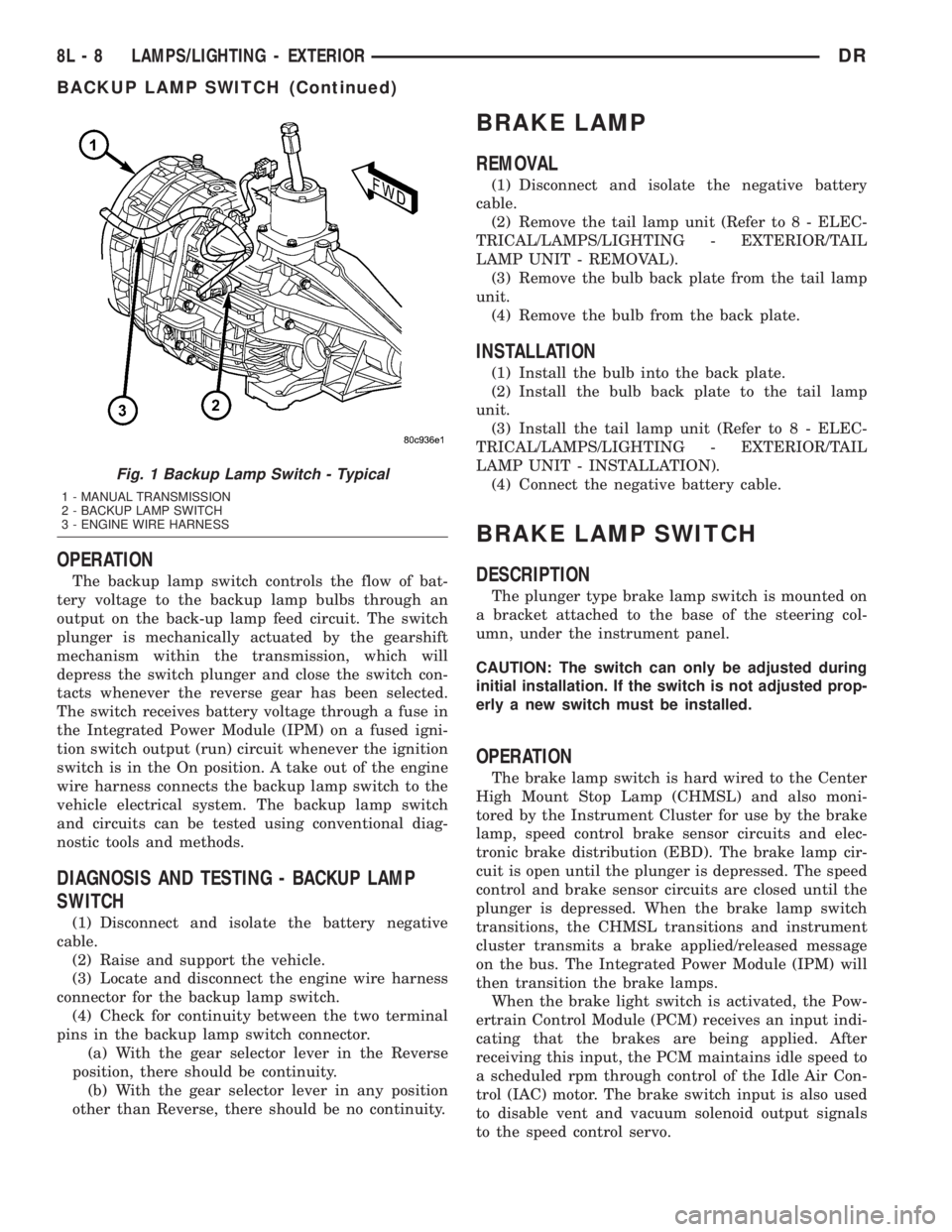
The backup lamp switch controls the flow of bat-
tery voltage to the backup lamp bulbs through an
output on the back-up lamp feed circuit. The switch
plunger is mechanically actuated by the gearshift
mechanism within the transmission, which will
depress the switch plunger and close the switch con-
tacts whenever the reverse gear has been selected.
The switch receives battery voltage through a fuse in
the Integrated Power Module (IPM) on a fused igni-
tion switch output (run) circuit whenever the ignition
switch is in the On position. A take out of the engine
wire harness connects the backup lamp switch to the
vehicle electrical system. The backup lamp switch
and circuits can be tested using conventional diag-
nostic tools and methods.
DIAGNOSIS AND TESTING - BACKUP LAMP
SWITCH
(1) Disconnect and isolate the battery negative
cable.
(2) Raise and support the vehicle.
(3) Locate and disconnect the engine wire harness
connector for the backup lamp switch.
(4) Check for continuity between the two terminal
pins in the backup lamp switch connector.
(a) With the gear selector lever in the Reverse
position, there should be continuity.
(b) With the gear selector lever in any position
other than Reverse, there should be no continuity.
BRAKE LAMP
REMOVAL
(1) Disconnect and isolate the negative battery
cable.
(2) Remove the tail lamp unit (Refer to 8 - ELEC-
TRICAL/LAMPS/LIGHTING - EXTERIOR/TAIL
LAMP UNIT - REMOVAL).
(3) Remove the bulb back plate from the tail lamp
unit.
(4) Remove the bulb from the back plate.
INSTALLATION
(1) Install the bulb into the back plate.
(2) Install the bulb back plate to the tail lamp
unit.
(3) Install the tail lamp unit (Refer to 8 - ELEC-
TRICAL/LAMPS/LIGHTING - EXTERIOR/TAIL
LAMP UNIT - INSTALLATION).
(4) Connect the negative battery cable.
BRAKE LAMP SWITCH
DESCRIPTION
The plunger type brake lamp switch is mounted on
a bracket attached to the base of the steering col-
umn, under the instrument panel.
CAUTION: The switch can only be adjusted during
initial installation. If the switch is not adjusted prop-
erly a new switch must be installed.
OPERATION
The brake lamp switch is hard wired to the Center
High Mount Stop Lamp (CHMSL) and also moni-
tored by the Instrument Cluster for use by the brake
lamp, speed control brake sensor circuits and elec-
tronic brake distribution (EBD). The brake lamp cir-
cuit is open until the plunger is depressed. The speed
control and brake sensor circuits are closed until the
plunger is depressed. When the brake lamp switch
transitions, the CHMSL transitions and instrument
cluster transmits a brake applied/released message
on the bus. The Integrated Power Module (IPM) will
then transition the brake lamps.
When the brake light switch is activated, the Pow-
ertrain Control Module (PCM) receives an input indi-
cating that the brakes are being applied. After
receiving this input, the PCM maintains idle speed to
a scheduled rpm through control of the Idle Air Con-
trol (IAC) motor. The brake switch input is also used
to disable vent and vacuum solenoid output signals
to the speed control servo.
Fig. 1 Backup Lamp Switch - Typical
1 - MANUAL TRANSMISSION
2 - BACKUP LAMP SWITCH
3 - ENGINE WIRE HARNESS
8L - 8 LAMPS/LIGHTING - EXTERIORDR
BACKUP LAMP SWITCH (Continued)