CD changer DODGE RAM 2003 Service Repair Manual
[x] Cancel search | Manufacturer: DODGE, Model Year: 2003, Model line: RAM, Model: DODGE RAM 2003Pages: 2895, PDF Size: 83.15 MB
Page 370 of 2895
INSTALLATION
(1) Install antenna cable to instrument panel by
pressing retaining fasteners into position.
(2) Connect instrument panel antenna cable to
antenna body and cable.
(3) Install radio (Refer to 8 - ELECTRICAL/AU-
DIO/RADIO - INSTALLATION).
(4) Install the instrument panel lower right center
bezel (Refer to 23 - BODY/INSTRUMENT PANEL/IP
LOWER RIGHT CENTER BEZEL - INSTALLA-
TION).
(5) Install the instrument panel center bezel (Refer
to 23 - BODY/INSTRUMENT PANEL/INSTRUMENT
PANEL CENTER BEZEL - INSTALLATION).
(6) Install the glove box (Refer to 23 - BODY/IN-
STRUMENT PANEL/GLOVE BOX - INSTALLA-
TION).
(7) Connect the battery negative cable.
RADIO
DESCRIPTION
Available factory-installed radio receivers for this
model include:
²AM/FM/cassette with CD changer control fea-
ture (RBB sales code)
²AM/FM/cassette/CD/graphic equalizer with CD
changer control feature (RAZ sales code)
²AM/FM/CD with CD changer control feature
(RBK sales code)
²AM/FM/CD with 6 CD changer (RBQ sales code)
²AM/FM/cassette/CD (RBY sales code) - export
only
All factory-installed radio receivers can communi-
cate on the Programmable Communications Interface(PCI) data bus network. All factory-installed receiv-
ers are stereo Electronically Tuned Radios (ETR) and
include an electronic digital clock function.
These radio receivers can only be serviced by an
authorized radio repair station. See the latest War-
ranty Policies and Procedures manual for a current
listing of authorized radio repair stations.
OPERATION
The radio receiver operates on ignition switched
battery current that is available only when the igni-
tion switch is in the On or Accessory positions. The
electronic digital clock function of the radio operates
on fused battery current supplied through the IOD
fuse, regardless of the ignition switch position.
For more information on the features, setting pro-
cedures, and control functions for each of the avail-
able factory-installed radio receivers, refer to the
owner's manual.
REMOVAL
(1) Disconnect and isolate the battery negative
cable.
(2) Remove center instrument panel bezel (Refer to
23 - BODY/INSTRUMENT PANEL/INSTRUMENT
PANEL CENTER BEZEL - REMOVAL).
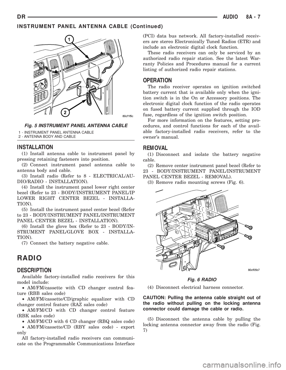
(3) Remove radio mounting screws (Fig. 6).
(4) Disconnect electrical harness connector.
CAUTION: Pulling the antenna cable straight out of
the radio without pulling on the locking antenna
connector could damage the cable or radio.
(5) Disconnect the antenna cable by pulling the
locking antenna connector away from the radio (Fig.
7)
Fig. 5 INSTRUMENT PANEL ANTENNA CABLE
1 - INSTRUMENT PANEL ANTENNA CABLE
2 - ANTENNA BODY AND CABLE
Fig. 6 RADIO
DRAUDIO 8A - 7
INSTRUMENT PANEL ANTENNA CABLE (Continued)
Page 373 of 2895
INSTALLATION
BED TO CAB
(1) Install the ground strap and retaining bolts.
Tighten to 5 N´m (45 in. lbs.).
(2) Connect the battery negative cable.
ENGINE TO HEAT SHIELD
(1) Install the retaining nut and ground strap to
the plenum. Tighten to 8 N´m (70 in. lbs.).
(2) Install the retaining bolt and ground strap to
the engine cylinder heads. Tighten to 12 N´m (106 in.
lbs.).
(3) Connect the battery negative cable.
REMOTE SWITCHES
DESCRIPTION
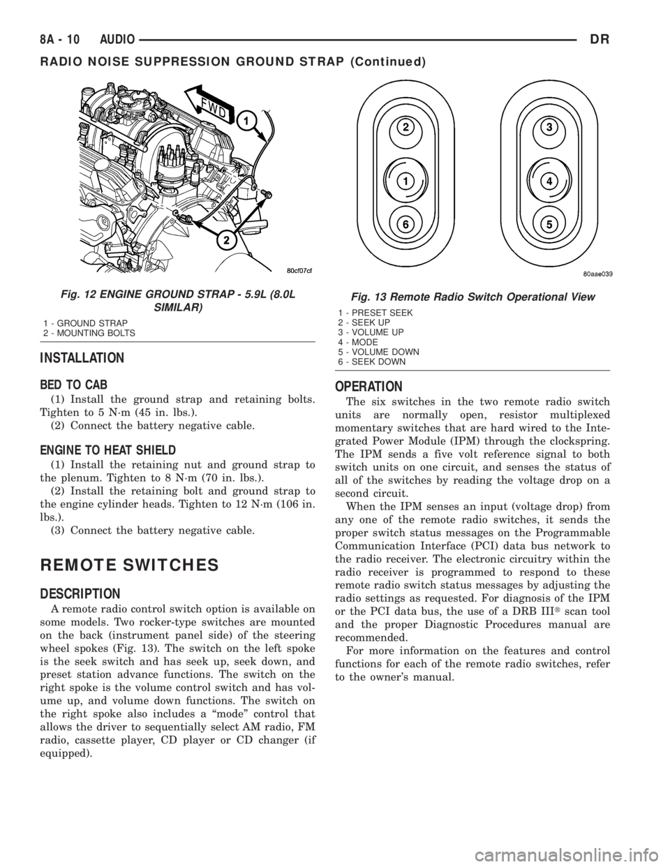
A remote radio control switch option is available on
some models. Two rocker-type switches are mounted
on the back (instrument panel side) of the steering
wheel spokes (Fig. 13). The switch on the left spoke
is the seek switch and has seek up, seek down, and
preset station advance functions. The switch on the
right spoke is the volume control switch and has vol-
ume up, and volume down functions. The switch on
the right spoke also includes a ªmodeº control that
allows the driver to sequentially select AM radio, FM
radio, cassette player, CD player or CD changer (if
equipped).
OPERATION
The six switches in the two remote radio switch
units are normally open, resistor multiplexed
momentary switches that are hard wired to the Inte-
grated Power Module (IPM) through the clockspring.
The IPM sends a five volt reference signal to both
switch units on one circuit, and senses the status of
all of the switches by reading the voltage drop on a
second circuit.
When the IPM senses an input (voltage drop) from
any one of the remote radio switches, it sends the
proper switch status messages on the Programmable
Communication Interface (PCI) data bus network to
the radio receiver. The electronic circuitry within the
radio receiver is programmed to respond to these
remote radio switch status messages by adjusting the
radio settings as requested. For diagnosis of the IPM
or the PCI data bus, the use of a DRB IIItscan tool
and the proper Diagnostic Procedures manual are
recommended.
For more information on the features and control
functions for each of the remote radio switches, refer
to the owner's manual.
Fig. 12 ENGINE GROUND STRAP - 5.9L (8.0L
SIMILAR)
1 - GROUND STRAP
2 - MOUNTING BOLTS
Fig. 13 Remote Radio Switch Operational View
1 - PRESET SEEK
2 - SEEK UP
3 - VOLUME UP
4 - MODE
5 - VOLUME DOWN
6 - SEEK DOWN
8A - 10 AUDIODR
RADIO NOISE SUPPRESSION GROUND STRAP (Continued)
Page 1670 of 2895
(3)Pre-lube the turbocharger.Pour 50 to 60 cc
(2 to 3 oz.) clean engine oil in the oil supply line fit-
ting. Carefully rotate the turbocharger impeller by
hand to distribute the oil thoroughly.
(4) Install and tighten the oil supply line to 24
N´m (18 ft. lbs.) torque.
(5) Position the charge air cooler inlet pipe to the
turbocharger. With the clamp in position, tighten the
clamp nut to 11 N´m (95 in. lbs.) torque.
(6) Position the air inlet hose to the turbocharger
(Fig. 18). Tighten the clamp to 11 N´m (95 in. lbs.)
torque.
(7) Raise vehicle on hoist.
(8) Connect the exhaust pipe to the turbocharger
and tighten the bolts to 34 N´m (25 ft. lbs.) torque.
(9) Lower the vehicle.
(10) Connect the battery negative cables.
(11) Start the engine to check for leaks.
CHARGE AIR COOLER AND
PLUMBING
DESCRIPTION
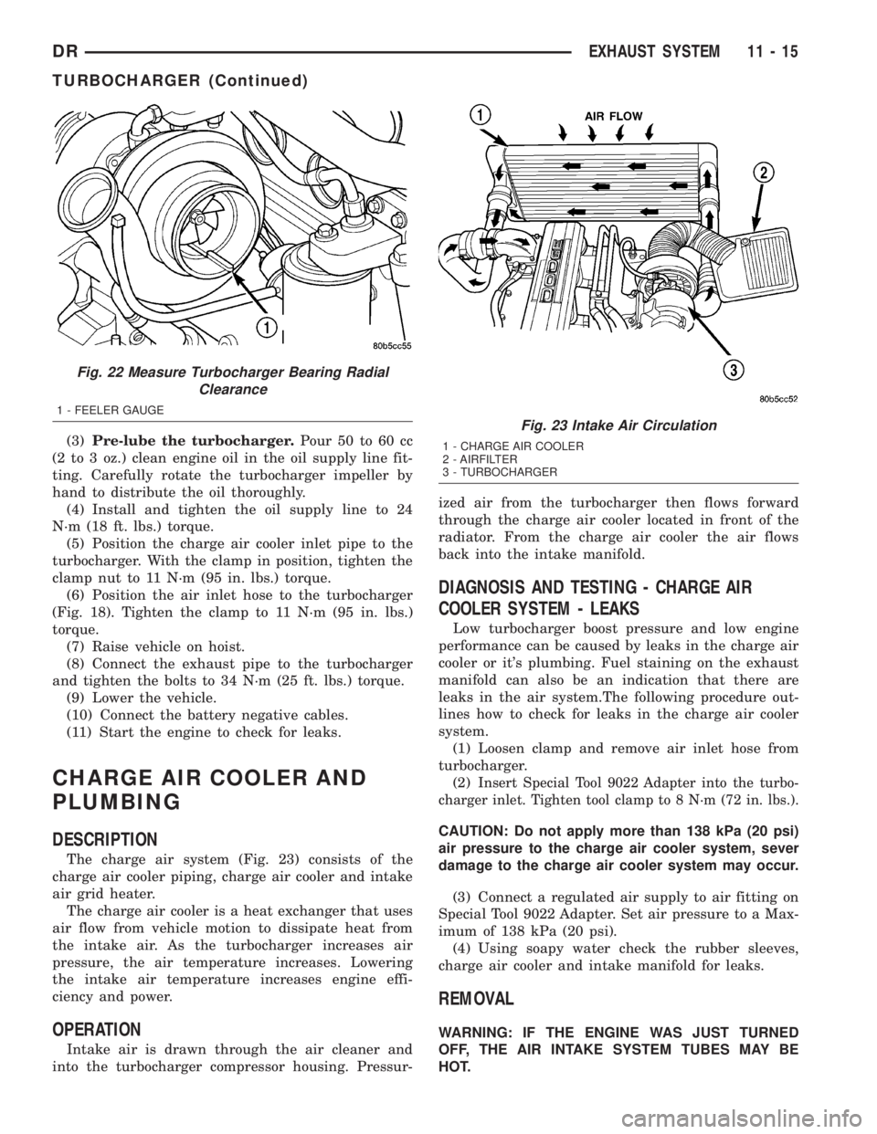
The charge air system (Fig. 23) consists of the
charge air cooler piping, charge air cooler and intake
air grid heater.
The charge air cooler is a heat exchanger that uses
air flow from vehicle motion to dissipate heat from
the intake air. As the turbocharger increases air
pressure, the air temperature increases. Lowering
the intake air temperature increases engine effi-
ciency and power.
OPERATION
Intake air is drawn through the air cleaner and
into the turbocharger compressor housing. Pressur-ized air from the turbocharger then flows forward
through the charge air cooler located in front of the
radiator. From the charge air cooler the air flows
back into the intake manifold.
DIAGNOSIS AND TESTING - CHARGE AIR
COOLER SYSTEM - LEAKS
Low turbocharger boost pressure and low engine
performance can be caused by leaks in the charge air
cooler or it's plumbing. Fuel staining on the exhaust
manifold can also be an indication that there are
leaks in the air system.The following procedure out-
lines how to check for leaks in the charge air cooler
system.
(1) Loosen clamp and remove air inlet hose from
turbocharger.
(2)
Insert Special Tool 9022 Adapter into the turbo-
charger inlet. Tighten tool clamp to 8 N´m (72 in. lbs.).
CAUTION: Do not apply more than 138 kPa (20 psi)
air pressure to the charge air cooler system, sever
damage to the charge air cooler system may occur.
(3) Connect a regulated air supply to air fitting on
Special Tool 9022 Adapter. Set air pressure to a Max-
imum of 138 kPa (20 psi).
(4) Using soapy water check the rubber sleeves,
charge air cooler and intake manifold for leaks.
REMOVAL
WARNING: IF THE ENGINE WAS JUST TURNED
OFF, THE AIR INTAKE SYSTEM TUBES MAY BE
HOT.
Fig. 22 Measure Turbocharger Bearing Radial
Clearance
1 - FEELER GAUGE
Fig. 23 Intake Air Circulation
1 - CHARGE AIR COOLER
2 - AIRFILTER
3 - TURBOCHARGER
DREXHAUST SYSTEM 11 - 15
TURBOCHARGER (Continued)
Page 2814 of 2895
(7) Evacuate the refrigerant system. (Refer to 24 -
HEATING & AIR CONDITIONING/PLUMBING -
STANDARD PROCEDURE - REFRIGERANT SYS-
TEM EVACUATE)
(8) Charge the refrigerant system. (Refer to 24 -
HEATING & AIR CONDITIONING/PLUMBING -
STANDARD PROCEDURE - REFRIGERANT SYS-
TEM CHARGE)
INSTALLATION - 5.9L DIESEL ENGINE
WARNING: REVIEW THE WARNINGS AND CAU-
TIONS IN THE FRONT OF THIS SECTION BEFORE
PERFORMING THE FOLLOWING OPERATION.
(Refer to 24 - HEATING & AIR CONDITIONING/
PLUMBING - WARNING) (Refer to 24 - HEATING &
AIR CONDITIONING/PLUMBING - CAUTION)(Refer to
24 - HEATING & AIR CONDITIONING/PLUMBING -
CAUTION - REFRIGERANT HOSES/LINES/TUBES
PRECAUTIONS)
NOTE: If a replacement compressor is being
installed, be certain to check the refrigerant oil
level. (Refer to 24 - HEATING & AIR CONDITIONING/
PLUMBING/REFRIGERANT OIL - STANDARD PRO-
CEDURE) Use only refrigerant oil of the type
recommended for the compressor in the vehicle.
(Refer to 24 - HEATING & AIR CONDITIONING/
PLUMBING/REFRIGERANT OIL - DESCRIPTION)
(1) Install the compressor to the mounting bracket.
Tighten the four mounting bolts to 24 N´m (210 in.
lbs.).
(2) Remove the tape or plugs from all of the
opened refrigerant line fittings. Install the suction
and discharge line manifold to the compressor. (Refer
to 24 - HEATING & AIR CONDITIONING/PLUMB-
ING/A/C SUCTION AND DISCHARGE LINE -
INSTALLATION)
(3) Install the serpentine drive belt(Refer to 7 -
COOLING/ACCESSORY DRIVE/DRIVE BELTS -
INSTALLATION).
(4) Plug in the compressor clutch coil wire harness
connector.
(5) Connect the battery negative cable.
(6) Evacuate the refrigerant system. (Refer to 24 -
HEATING & AIR CONDITIONING/PLUMBING -
STANDARD PROCEDURE - REFRIGERANT SYS-
TEM EVACUATE)
(7) Charge the refrigerant system. (Refer to 24 -
HEATING & AIR CONDITIONING/PLUMBING -
STANDARD PROCEDURE - REFRIGERANT SYS-
TEM CHARGE)
A/C CONDENSER
DESCRIPTION
The condenser is located in the air flow next to the
engine cooling radiator. The condenser is a heat
exchanger that allows the high-pressure refrigerant
gas being discharged by the compressor to give up its
heat to the air passing over the condenser fins.
OPERATION
When the refrigerant gas gives up its heat, it con-
denses. When the refrigerant leaves the condenser, it
has become a high-pressure liquid refrigerant. The
volume of air flowing over the condenser fins is crit-
ical to the proper cooling performance of the air con-
ditioning system. Therefore, it is important that
there are no objects placed in front of the radiator
grille openings in the front of the vehicle or foreign
material on the condenser fins that might obstruct
proper air flow. Also, any factory-installed air seals or
shrouds must be properly reinstalled following radia-
tor or condenser service.
The condenser cannot be repaired and, if faulty or
damaged, it must be replaced.
REMOVAL
REMOVAL - 3.7, 4.7 and 5.7L ENGINES
WARNING: REVIEW THE WARNINGS AND CAU-
TIONS IN THE FRONT OF THIS SECTION BEFORE
PERFORMING THE FOLLOWING OPERATION.
(Refer to 24 - HEATING & AIR CONDITIONING/
PLUMBING - WARNING) (Refer to 24 - HEATING &
AIR CONDITIONING/PLUMBING - CAUTION)
(1) Disconnect and isolate the battery negative
cable.
(2) Recover the refrigerant from the refrigerant
system. (Refer to 24 - HEATING & AIR CONDI-
TIONING/PLUMBING - STANDARD PROCEDURE -
REFRIGERANT RECOVERY)
(3) Disconnect the discharge line refrigerant line
fitting at the condenser inlet. (Refer to 24 - HEAT-
ING & AIR CONDITIONING/PLUMBING - STAN-
DARD PROCEDURE - A/C LINE COUPLERS)
Install plugs in, or tape over all of the opened refrig-
erant line fittings.
(4) Disconnect the liquid line refrigerant line fit-
ting at the condenser outlet. (Refer to 24 - HEATING
& AIR CONDITIONING/PLUMBING - STANDARD
PROCEDURE - A/C LINE COUPLERS) Install plugs
in, or tape over all of the opened refrigerant line fit-
tings.
DRPLUMBING 24 - 39
A/C COMPRESSOR (Continued)
Page 2825 of 2895
INSTALLATION
WARNING: REVIEW THE WARNINGS AND CAU-
TIONS IN THE FRONT OF THIS SECTION BEFORE
PERFORMING THE FOLLOWING OPERATION.
(Refer to 24 - HEATING & AIR CONDITIONING/
PLUMBING - WARNING) (Refer to 24 - HEATING &
AIR CONDITIONING/PLUMBING - CAUTION)(Refer to
24 - HEATING & AIR CONDITIONING/PLUMBING -
CAUTION - REFRIGERANT HOSES/LINES/TUBES
PRECAUTIONS)
(1) Install the accumulator to the bulkhead but do
not tighten yet.
(2) Remove the tape or plugs from the refrigerant
line fittings on the accumulator inlet and the evapo-
rator outlet. Connect the accumulator inlet refriger-
ant line coupler to the evaporator outlet. (Refer to 24
- HEATING & AIR CONDITIONING/PLUMBING -
STANDARD PROCEDURE - A/C LINE COUPLERS)
(3) Remove the tape or plugs from the refrigerant
line fittings on the suction line and the accumulator
outlet. Connect the suction line refrigerant line cou-
pler to the accumulator outlet. (Refer to 24 - HEAT-
ING & AIR CONDITIONING/PLUMBING -
STANDARD PROCEDURE - A/C LINE COUPLERS)
(4) Tighten the accumulator fasteners to 4.5 N´m
(40 in. lbs.).
(5) Connect the battery negative cable.
(6) Evacuate the refrigerant system. (Refer to 24 -
HEATING & AIR CONDITIONING/PLUMBING -
STANDARD PROCEDURE - REFRIGERANT SYS-
TEM EVACUATE)
(7) Charge the refrigerant system. (Refer to 24 -
HEATING & AIR CONDITIONING/PLUMBING -
STANDARD PROCEDURE - REFRIGERANT SYS-
TEM CHARGE)
NOTE: If the accumulator is replaced, add 60 milli-
liters (2 fluid ounces) of refrigerant oil to the refrig-
erant system. Use only refrigerant oil of the type
recommended for the compressor in the vehicle.
HEATER CORE
DESCRIPTION
The heater core is located in the HVAC housing,
under the instrument panel. It is a heat exchanger
made of rows of tubes and fins.
The heater core is not repairable and if damaged it
must be replaced.
OPERATION
Engine coolant is circulated through heater hoses
to the heater core at all times. As the coolant flowsthrough the heater core, heat removed from the
engine is transferred to the heater core fins and
tubes. Air directed through the heater core picks up
the heat from the heater core fins. The blend door
allows control of the heater output air temperature
by controlling how much of the air flowing through
the HVAC housing is directed through the heater
core. The blower motor speed controls the volume of
air flowing through the HVAC housing.
The heater core cannot be repaired and, if faulty or
damaged, it must be replaced.
REMOVAL
NOTE: Disassembly of the HVAC housing is not
required to remove heater core.
(1) Remove the HVAC housing from the vehicle.
(Refer to 24 - HEATING & AIR CONDITIONING/
DISTRIBUTION/HVAC HOUSING - REMOVAL)
(2) Remove the screws and retainers that secure
the heater core to the HVAC housing.
(3) Lift the heater core out of the heater-A/C hous-
ing.
(4) Inspect all seals and repair or replace as
required.
INSTALLATION
(1) Place the heater core into the HVAC housing.
(2) Snap the retainers for the heater core to the
housing. Install and tighten the screws that secure
the heater core to the HVAC housing (if equipped).
Tighten the screws to 2.2 N´m (20 in. lbs.).
(3) Reinstall the HVAC housing in the vehicle.
(Refer to 24 - HEATING & AIR CONDITIONING/
DISTRIBUTION/HVAC HOUSING - INSTALLA-
TION)
REFRIGERANT
DESCRIPTION
The refrigerant used in this air conditioning sys-
tem is a HydroFluoroCarbon (HFC), type R-134a.
Unlike R-12, which is a ChloroFluoroCarbon (CFC),
R-134a refrigerant does not contain ozone-depleting
chlorine. R-134a refrigerant is a non-toxic, non-flam-
mable, clear, and colorless liquefied gas.
Even though R-134a does not contain chlorine, it
must be reclaimed and recycled just like CFC-type
refrigerants. This is because R-134a is a greenhouse
gas and can contribute to global warming.
OPERATION
R-134a refrigerant is not compatible with R-12
refrigerant in an air conditioning system. Even a
24 - 50 PLUMBINGDR
ACCUMULATOR (Continued)