open hood DODGE RAM 2003 Service Repair Manual
[x] Cancel search | Manufacturer: DODGE, Model Year: 2003, Model line: RAM, Model: DODGE RAM 2003Pages: 2895, PDF Size: 83.15 MB
Page 26 of 2895
JUMP STARTING
STANDARD PROCEDURE - JUMP STARTING
WARNING: REVIEW ALL SAFETY PRECAUTIONS
AND WARNINGS IN THE BATTERY SYSTEM SEC-
TION OF THE SERVICE MANUAL. (Refer to 8 -
ELECTRICAL/BATTERY SYSTEM/BATTERY - STAN-
DARD PROCEDURE)
²DO NOT JUMP START A FROZEN BATTERY,
PERSONAL INJURY CAN RESULT.
²IF EQUIPPED, DO NOT JUMP START WHEN
MAINTENANCE FREE BATTERY INDICATOR DOT IS
YELLOW OR BRIGHT COLOR.
²DO NOT JUMP START A VEHICLE WHEN THE
BATTERY FLUID IS BELOW THE TOP OF LEAD
PLATES.
²DO NOT ALLOW JUMPER CABLE CLAMPS TO
TOUCH EACH OTHER WHEN CONNECTED TO A
BOOSTER SOURCE.
²DO NOT USE OPEN FLAME NEAR BATTERY.
²REMOVE METALLIC JEWELRY WORN ON
HANDS OR WRISTS TO AVOID INJURY BY ACCI-
DENTAL ARCING OF BATTERY CURRENT.
²WHEN USING A HIGH OUTPUT BOOSTING
DEVICE, DO NOT ALLOW BATTERY VOLTAGE TO
EXCEED 16 VOLTS. REFER TO INSTRUCTIONS
PROVIDED WITH DEVICE BEING USED.
FAILURE TO FOLLOW THESE INSTRUCTIONS MAY
RESULT IN PERSONAL INJURY.
CAUTION: When using another vehicle as a
booster, do not allow vehicles to touch. Electrical
systems can be damaged on either vehicle.
TO JUMP START A DISABLED VEHICLE:
(1) Raise hood on disabled vehicle and visually
inspect engine compartment for:
²Battery cable clamp condition, clean if necessary.
²Frozen battery.
²Yellow or bright color test indicator, if equipped.
²Low battery fluid level.
²Generator drive belt condition and tension.
²Fuel fumes or leakage, correct if necessary.CAUTION: If the cause of starting problem on dis-
abled vehicle is severe, damage to booster vehicle
charging system can result.
(2) When using another vehicle as a booster
source, park the booster vehicle within cable reach.
Turn off all accessories, set the parking brake, place
the automatic transmission in PARK or the manual
transmission in NEUTRAL and turn the ignition
OFF.
(3) On disabled vehicle, place gear selector in park
or neutral and set park brake. Turn off all accesso-
ries.
(4) Connect jumper cables to booster battery. RED
clamp to positive terminal (+). BLACK clamp to neg-
ative terminal (-). DO NOT allow clamps at opposite
end of cables to touch, electrical arc will result.
Review all warnings in this procedure.
(5) On disabled vehicle, connect RED jumper cable
clamp to positive (+) terminal. Connect BLACK
jumper cable clamp to engine ground as close to the
ground cable attaching point as possible.
(6) Start the engine in the vehicle which has the
booster battery, let the engine idle a few minutes,
then start the engine in the vehicle with the dis-
charged battery.
CAUTION: Do not crank starter motor on disabled
vehicle for more than 15 seconds, starter will over-
heat and could fail.
(7) Allow battery in disabled vehicle to charge to
at least 12.4 volts (75% charge) before attempting to
start engine. If engine does not start within 15 sec-
onds, stop cranking engine and allow starter to cool
(15 min.), before cranking again.
DISCONNECT CABLE CLAMPS AS FOLLOWS:
²Disconnect BLACK cable clamp from engine
ground on disabled vehicle.
²When using a Booster vehicle, disconnect
BLACK cable clamp from battery negative terminal.
Disconnect RED cable clamp from battery positive
terminal.
²Disconnect RED cable clamp from battery posi-
tive terminal on disabled vehicle.
DRLUBRICATION & MAINTENANCE 0 - 13
Page 271 of 2895
then opens the outlet valve, which also opens the
return circuit to the accumulators. Fluid pressure is
allowed to bleed off (decrease) as needed to prevent
wheel lock.
Once the period of high wheel slip has ended, the
CAB closes the outlet valve and begins a pressure
increase or hold cycle as needed.
PRESSURE HOLD
Both solenoid valves are closed in the pressure
hold cycle but only the inlet valve is energized. Fluid
apply pressure in the control channel is maintained
at a constant rate. The CAB maintains the hold cycle
until sensor inputs indicate a pressure change is nec-
essary.
PRESSURE INCREASE
The inlet valve is open and the outlet valve is
closed during the pressure increase cycle. The pres-
sure increase cycle is used to reapply thew brakes.
This cycle controls re-application of fluid apply pres-
sure.
REMOVAL
(1) Install a prop rod on the brake pedal to keep
pressure on the brake system.
(2) Disconnect the battery cables from the battery.
(3) Remove the battery.
(4) Disconnect the two electrical harness connec-
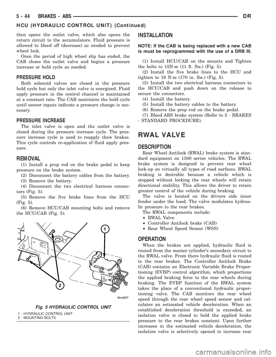
tors (Fig. 5).
(5) Remove the five brake lines from the HCU
(Fig. 5).
(6) Remove HCU/CAB mounting bolts and remove
the HCU/CAB (Fig. 5).
INSTALLATION
NOTE: If the CAB is being replaced with a new CAB
is must be reprogrammed with the use of a DRB III.
(1) Install HCU/CAB on the mounts and Tighten
the bolts to 15N´m (11 ft. lbs.) (Fig. 5).
(2) Install the five brake lines to the HCU and
tighten to 19 N´m (170 in. lbs.) (Fig. 5).
(3) Install the two electrical harness connectors to
the HCU/CAB and push down on the release to
secure the connectors.
(4) Install the battery.
(5) Install the battery cables to the battery.
(6) Remove the prop rod on the brake pedal.
(7) Bleed ABS brake system (Refer to 5 - BRAKES
- STANDARD PROCEDURE).
RWAL VALVE
DESCRIPTION
Rear Wheel Antilock (RWAL) brake system is stan-
dard equipment on 1500 series vehicles. The RWAL
brake system is designed to prevent rear wheel
lock-up on virtually all types of road surfaces. RWAL
braking is desirable because a vehicle which is
stopped without locking the rear wheels will retain
directional stability. This allows the driver to retain
greater control of the vehicle during braking.
The valve is located on the drivers side inner
fender under the hood. The valve modulates hydrau-
lic pressure to the rear brakes.
The RWAL components include:
²RWAL Valve
²Controller Antilock brake (CAB)
²Rear Wheel Speed Sensor (WSS)
OPERATION
When the brakes are applied, hydraulic fluid is
routed from the master cylinder's secondary circuit to
the RWAL valve. From there hydraulic fluid is routed
to the rear brakes. The Controller Antilock Brake
(CAB) contains an Electronic Variable Brake Propor-
tioning (EVBP) control algorithm, which proportions
the applied braking force to the rear wheels during
braking. The EVBP function of the RWAL system
takes the place of a conventional hydraulic propor-
tioning valve. The CAB monitors the rear wheel
speed through the rear wheel speed sensor and cal-
culates an estimated vehicle deceleration. When an
established deceleration threshold is exceeded, an
isolation valve is closed to hold the applied brake
pressure to the rear brakes constant. Upon further
increases in the estimated vehicle deceleration, the
isolation valve is selectively opened to increase rear
Fig. 5 HYDRAULIC CONTROL UNIT
1 - HYDRAULIC CONTROL UNIT
2 - MOUNTING BOLTS
5 - 44 BRAKES - ABSDR
HCU (HYDRAULIC CONTROL UNIT) (Continued)
Page 417 of 2895
ELECTRONIC MODULE IGNITION-OFF DRAW (IOD) TABLE
ModuleTime Out?
(If Yes, Interval And Wake-Up Input)IODIOD After Time
Out
ElectroMechanical
Instrument Cluster
(EMIC)No 0.44 milliampere N/A
Combination Flasher No 0.08 milliampere N/A
(2) Determine that the underhood lamp is operat-
ing properly, then disconnect the lamp wire harness
connector or remove the lamp bulb.
(3) Disconnect the battery negative cable.
(4) Set an electronic digital multi-meter to its
highest amperage scale. Connect the multi-meter
between the disconnected battery negative cable ter-
minal clamp and the battery negative terminal post.
Make sure that the doors remain closed so that the
illuminated entry system is not activated. The multi-
meter amperage reading may remain high for up to
three minutes, or may not give any reading at all
while set in the highest amperage scale, depending
upon the electrical equipment in the vehicle. The
multi-meter leads must be securely clamped to the
battery negative cable terminal clamp and the bat-
tery negative terminal post. If continuity between the
battery negative terminal post and the negative cable
terminal clamp is lost during any part of the IOD
test, the electronic timer function will be activated
and all of the tests will have to be repeated.
(5) After about three minutes, the high-amperage
IOD reading on the multi-meter should become very
low or nonexistent, depending upon the electrical
equipment in the vehicle. If the amperage reading
remains high, remove and replace each fuse or circuit
breaker in the Integrated Power Module (IPM), one
at a time until the amperage reading becomes very
low, or nonexistent. Refer to the appropriate wiring
information in this service manual for complete Inte-
grated Power Module fuse, circuit breaker, and cir-
cuit identification. This will isolate each circuit and
identify the circuit that is the source of the high-am-
perage IOD. If the amperage reading remains high
after removing and replacing each fuse and circuit
breaker, disconnect the wire harness from the gener-
ator. If the amperage reading now becomes very low
or nonexistent, refer to Charging System for the
proper charging system diagnosis and testing proce-
dures. After the high-amperage IOD has been cor-
rected, switch the multi-meter to progressively lower
amperage scales and, if necessary, repeat the fuse
and circuit breaker remove-and-replace process to
identify and correct all sources of excessive IOD. It is
now safe to select the lowest milliampere scale of the
multi-meter to check the low-amperage IOD.CAUTION: Do not open any doors, or turn on any
electrical accessories with the lowest milliampere
scale selected, or the multi-meter may be damaged.
(6) Observe the multi-meter reading. The low-am-
perage IOD should not exceed thirty-five milliam-
peres (0.035 ampere). If the current draw exceeds
thirty-five milliamperes, isolate each circuit using the
fuse and circuit breaker remove-and-replace process
in Step 5. The multi-meter reading will drop to
within the acceptable limit when the source of the
excessive current draw is disconnected. Repair this
circuit as required; whether a wiring short, incorrect
switch adjustment, or a component failure is at fault.
STANDARD PROCEDURE - USING MICRO 420
BATTERY TESTER
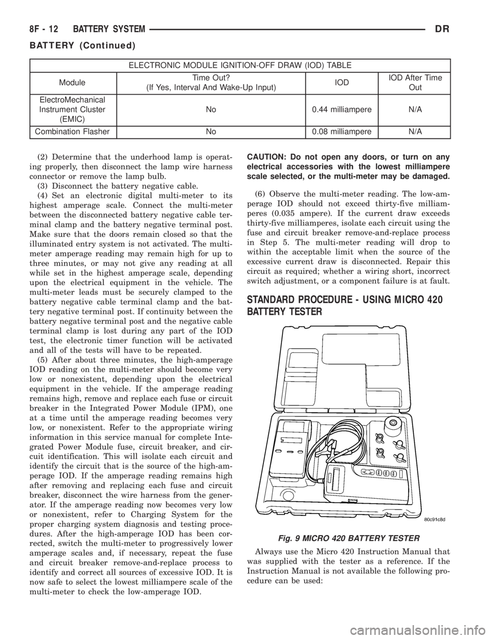
Always use the Micro 420 Instruction Manual that
was supplied with the tester as a reference. If the
Instruction Manual is not available the following pro-
cedure can be used:
Fig. 9 MICRO 420 BATTERY TESTER
8F - 12 BATTERY SYSTEMDR
BATTERY (Continued)
Page 495 of 2895
WASHER FLUID INDICATOR
DESCRIPTION.........................42
OPERATION...........................42WATER-IN-FUEL INDICATOR
DESCRIPTION.........................43
OPERATION...........................43
INSTRUMENT CLUSTER
DESCRIPTION
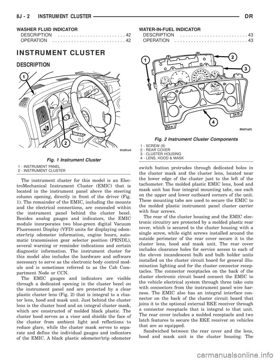
The instrument cluster for this model is an Elec-
troMechanical Instrument Cluster (EMIC) that is
located in the instrument panel above the steering
column opening, directly in front of the driver (Fig.
1). The remainder of the EMIC, including the mounts
and the electrical connections, are concealed within
the instrument panel behind the cluster bezel.
Besides analog gauges and indicators, the EMIC
module incorporates two blue-green digital Vacuum
Fluorescent Display (VFD) units for displaying odom-
eter/trip odometer information, engine hours, auto-
matic transmission gear selector position (PRNDL),
several warning or reminder indications and certain
diagnostic information. The instrument cluster for
this model also includes the hardware and software
necessary to serve as the electronic body control mod-
ule and is sometimes referred to as the Cab Com-
partment Node or CCN.
The EMIC gauges and indicators are visible
through a dedicated opening in the cluster bezel on
the instrument panel and are protected by a clear
plastic cluster lens (Fig. 2) that is integral to a clus-
ter lens, hood and mask unit. Just behind the cluster
lens is the cluster hood and an integral cluster mask,
which are constructed of molded black plastic. The
cluster hood serves as a visor and shields the face of
the cluster from ambient light and reflections to
reduce glare, while the cluster mask serves to sepa-
rate and define the individual gauges and indicators
of the EMIC. A black plastic odometer/trip odometerswitch button protrudes through dedicated holes in
the cluster mask and the cluster lens, located near
the lower edge of the cluster just to the left of the
tachometer. The molded plastic EMIC lens, hood and
mask unit has four integral mounting tabs, one each
on the upper and lower outboard corners of the unit.
These mounting tabs are used to secure the EMIC to
the molded plastic instrument panel cluster carrier
with four screws.
The rear of the cluster housing and the EMIC elec-
tronic circuitry are protected by a molded plastic rear
cover, which is secured to the cluster housing with a
single screw, while eight screws installed around the
outside perimeter of the rear cover secure it to the
cluster lens, hood and mask unit. The rear cover
includes clearance holes for service access to each of
the eleven incandescent bulb and bulb holder units
installed on the cluster circuit board for general illu-
mination lighting and for the cluster connector recep-
tacles. The connector receptacles on the back of the
cluster electronic circuit board connect the EMIC to
the vehicle electrical system through three take outs
with connectors from the instrument panel wire har-
ness. The EMIC also has an integral interface con-
nector on the back of the cluster circuit board that
joins it to the optional external RKE receiver through
a connector receptacle that is integral to that unit.
The rear cover includes a molded receptacle and two
latch features to secure the RKE receiver on vehicles
that are so equipped.
Sandwiched between the rear cover and the lens,
hood and mask unit is the cluster housing. The
Fig. 1 Instrument Cluster
1 - INSTRUMENT PANEL
2 - INSTRUMENT CLUSTER
Fig. 2 Instrument Cluster Components
1 - SCREW (9)
2 - REAR COVER
3 - CLUSTER HOUSING
4 - LENS, HOOD & MASK
8J - 2 INSTRUMENT CLUSTERDR
Page 539 of 2895
MULTI-FUNCTION SWITCH
DESCRIPTION - TURN SIGNAL SYSTEM.....17
OPERATION - TURN SIGNAL SYSTEM.......18
DIAGNOSIS AND TESTING - MULTI-
FUNCTION SWITCH...................18
REMOVAL.............................18
INSTALLATION.........................19
PARK LAMP RELAY
DESCRIPTION.........................19
OPERATION...........................19
DIAGNOSIS AND TESTING - PARK LAMP
RELAY..............................20
REMOVAL.............................20
INSTALLATION.........................21
PARK/TURN SIGNAL LAMP
REMOVAL.............................21
INSTALLATION.........................21TAIL LAMP
REMOVAL.............................21
INSTALLATION.........................21
TAIL LAMP UNIT
REMOVAL.............................21
INSTALLATION.........................21
TRAILER TOW WIRING
DESCRIPTION.........................22
TURN LAMP
REMOVAL.............................22
INSTALLATION.........................22
UNDERHOOD LAMP
REMOVAL.............................22
INSTALLATION.........................22
UNDERHOOD LAMP UNIT
REMOVAL.............................22
INSTALLATION.........................23
LAMPS/LIGHTING - EXTERIOR
DESCRIPTION
The exterior lighting system for this model include
the following components:
²Backup Lamps
²Brake Lamps
²Daytime Running Lamps
²Front Fog Lamps
²Hazard Warning Lamps
²Headlamps
²Park Lamps
²Turn Signal Lamps
Other components of the exterior lighting system
for this model include:
²Backup Lamp Switch
²Brake Lamp Switch
²Front Control Module
²Front Fog Lamp Relay
²Hazard Switch
²Multi-Function Switch
²Park Lamp Relay
²Trailer Tow Connectors
Some of the interior and exterior lighting functions
are governed by the front control module. The head-
lamp, dome, and door ajar switchs provide signals to
the instrument cluster. The instrument cluster sends
a J1850 message to the front control module to
enable the necessary components for illumination.
Hard wired circuitry connects the exterior lighting
system components to the electrical system of the
vehicle. Refer to the appropriate wiring information.
OPERATION
DAYTIME RUNNING LAMPS
Power is reduced using pulse-width modulation to
the high beams, where by the power is switched on
and off rapidly instead of remaining on continuously.
The duration and interval of the power pulses is pro-
grammed into the Front Control Module (FCM).
HEADLAMP SYSTEM
The instrument cluster monitors both the multi-
plexed headlamp and multifunction switches. The
instrument cluster transmits a J1850 bus message to
the front control module (FCM) to activate the head-
lamps. The headlamp system will default to head-
lamps ON position when ignition switch is ON and
when an open or short circuit failure occurs on the
headlamp switch input to the instrument cluster. The
system will return to normal operation when the
open or short is repaired. A fault will be reported by
the Instrument Cluster when a failure occurs on the
dimmer or headlamp switch input.
If the exterior lamps are ON, and the headlamp
switch is in any position other than OFF, with the
ignition switch OFF (LOCK) after 5 minutes, the
Instrument Cluster transmits a message via J1850
informing the the FCM. The FCM will then turn off
the headlamps, park lamps and fog lamps. This fea-
ture (load shed) prevents the vehicle battery from
being discharged when the vehicle lights have been
left ON.
HEADLAMP TIME DELAY SYSTEM
The headlamp time delay system is activated by
turning the headlamps ON (high or low beam) while
the engine is running, turning the ignition switch
OFF, and then turning the headlamp switch OFF
8L - 2 LAMPS/LIGHTING - EXTERIORDR
Page 566 of 2895
(1) With the ignition switch in the Off position,
simultaneously depress and hold theSTEP and
RESET buttons.
(2) Turn the ignition switch to the On position.
(3) Following completion of the test, the electronics
module will display one of the following messages:
a.Pass Self Test (EVIC only), PASS (CMTC)-
The electronics module is working properly.
b.Failed Self Test (EVIC only), FAIL (CMTC)-
The electronics module has an internal failure. The
electronics module is faulty and must be replaced.
c.Failed J1850 Communication (EVIC only),
BUS (CMTC)- The electronics module is not receiv-
ing proper message input through the J1850 PCI
data bus circuit. This can result from one or more
faulty electronic modules in the vehicle, or from a
faulty PCI data bus. The use of a DRB IIItscan tool
and the proper Diagnostic Procedures manual are
required for further diagnosis.
NOTE: If the compass functions, but accuracy is
suspect, it may be necessary to perform a variation
adjustment. This procedure allows the compass
unit to accommodate variations in the earth's mag-
netic field strength, based on geographic location.
Refer to Compass Variation Adjustment in the Stan-
dard Procedures section of this group.
NOTE: If the compass reading displays dashes, and
only ªCALº appears in the display, demagnetizing
may be necessary to remove excessive residual
magnetic fields from the vehicle. Refer to Compass
Demagnetizing in the Standard Procedures section
of this group.
STANDARD PROCEDURE
STANDARD PROCEDURE - READING/
COURTESY LAMP REPLACEMENT
(1) Open hood, disconnect and isolate the negative
battery cable.
(2) Remove the reading/courtesy lamp lens. Using
a trim stick, gently pry the forward edge of the read-
ing/courtesy lamp lens outward.
(3) Remove the reading/courtesy lamp socket from
the overhead console. Rotate the reading/courtesy
lamp socket one quarter turn counter clockwise.
(4) Remove the lamp and socket assembly.
(5) Reverse the above procedure to install.
STANDARD PROCEDURE - MODULE LENS
REPLACEMENT
(1) Remove the overhead console (Refer to 8 -
ELECTRICAL/OVERHEAD CONSOLE - REMOV-
AL).
(2) Remove the electronics module from the over-
head console. Refer to the procedure later in this sec-
tion.
(3) Unsnap the lens from the module and replace
lens as necessary.
STANDARD PROCEDURE - MODULE LAMP
REPLACEMENT
(1) Remove the overhead console (Refer to 8 -
ELECTRICAL/OVERHEAD CONSOLE - REMOV-
AL).
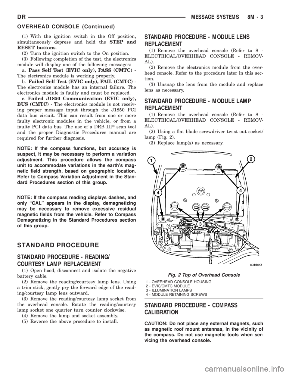
(2) Using a flat blade screwdriver twist out socket/
lamp (Fig. 2).
(3) Replace lamp(s) as necessary.
STANDARD PROCEDURE - COMPASS
CALIBRATION
CAUTION: Do not place any external magnets, such
as magnetic roof mount antennas, in the vicinity of
the compass. Do not use magnetic tools when ser-
vicing the overhead console.
Fig. 2 Top of Overhead Console
1 - OVERHEAD CONSOLE HOUSING
2 - EVIC/CMTC MODULE
3 - ILLUMINATION LAMPS
4 - MODULE RETAINING SCREWS
DRMESSAGE SYSTEMS 8M - 3
OVERHEAD CONSOLE (Continued)
Page 574 of 2895
then sends the proper ambient temperature mes-
sages to the EVIC, CMTC over the PCI J1850 data
bus.
The temperature function is supported by the
ambient temperature sensor, a wiring circuit, the
Front Control Module, the Programmable Communi-
cations Interface (PCI) data bus, and a portion of the
Electronics module. If any portion of the ambient
temperature sensor circuit fails, the Front Control
Module will self-diagnose the circuit.
For complete circuit diagrams, refer toWiring.
DIAGNOSIS AND TESTING
DIAGNOSIS AND TESTING - AMBIENT
TEMPERATURE SENSOR
(1) Turn the ignition switch to the Off position.
Disconnect and isolate the battery negative cable.
Disconnect the ambient temperature sensor wire har-
ness connector.
(2) Measure the resistance of the ambient temper-
ature sensor. At 24É C (75É F), the sensor resistance
should be approximately 10.3 kilohms. At 30É C (86É
F), the sensor resistance should be approximately
7.57 kilohms. The sensor resistance should decrease
as the temperature rises. If OK, refer toDiagnosis
and Testing - Ambient Temperature Sensor Cir-
cuitin this group. If not OK, replace the faulty
ambient temperature sensor.
NOTE: The ambient temperature sensor is a very
sensitive device. When testing, be certain the tem-
perature sensor has had time to stabilize (room
temperature) before attempting to read the sensor
resistance. Failure to let the ambient temperature
sensor temperature stabilize could result in a mis-
leading test.
DIAGNOSIS AND TESTING - AMBIENT
TEMPERATURE SENSOR CIRCUIT
(1) Turn the ignition switch to the Off position.
Disconnect and isolate the battery negative cable.
Disconnect the ambient temperature sensor wire har-
ness connector and the Front Control Module wire
harness connector.
(2) Connect a jumper wire between the two termi-
nals of the ambient temperature sensor wire harness
connector.
(3) Check for continuity between the sensor return
circuit and the ambient temperature sensor signal
circuit cavities of the Front Control Module wire har-
ness connector. There should be continuity. If OK, go
to Step 4. If not OK, repair the open sensor return or
signal circuit as required.(4) Remove the jumper wire from the ambient tem-
perature sensor wire harness connector. Check for
continuity between the sensor return circuit cavity of
the Front Control Module wire harness connector
and a good ground. There should be no continuity. If
OK, go to Step 5. If not OK, repair the shorted sen-
sor return circuit as required.
(5) Check for continuity between the ambient tem-
perature sensor signal circuit cavity of the Front
Control Module wire harness connector and a good
ground. There should be no continuity. If OK, refer to
Diagnosis and Testing - Overhead Consolein
this group. If not OK, repair the shorted ambient
temperature sensor signal circuit as required.
REMOVAL
(1) Open the hood.
(2) Disconnect and isolate the battery negative
cable.
(3) Working on the underside of the hood, remove
screw holding sensor to hood panel.
(4) Disconnect the sensor electrical connector and
remove sensor from vehicle.
INSTALLATION
(1) Connect the sensor electrical connector.
(2) Working on the underside of the hood, install
screw holding sensor to hood panel.
(3) Connect the battery negative cable.
(4) Close the hood.
UNIVERSAL TRANSMITTER
DESCRIPTION
Some DR models are equipped with a universal
transmitter transceiver. The universal transmitter is
integral to the Electronic Vehicle Information Center
(EVIC) and the Compass Mini-Trip Computer
(CMTC), which is located in the overhead console.
The only visible component of the universal transmit-
ter are the three transmitter push buttons centered
between the modules push buttons located just rear-
ward of the display screen in the overhead console.
The three universal transmitter push buttons are
identified with one, two or three light indicators so
that they be easily identified.
Each of the three universal transmitter push but-
tons control an independent radio transmitter chan-
nel. Each of these three channels can be trained to
transmit a different radio frequency signal for the
remote operation of garage door openers, motorized
gate openers, home or office lighting, security sys-
tems or just about any other device that can be
equipped with a radio receiver in the 286 to 399
MegaHertz (MHz) frequency range for remote opera-
DRMESSAGE SYSTEMS 8M - 11
AMBIENT TEMP SENSOR (Continued)
Page 683 of 2895
CHECK VALVE
DESCRIPTION
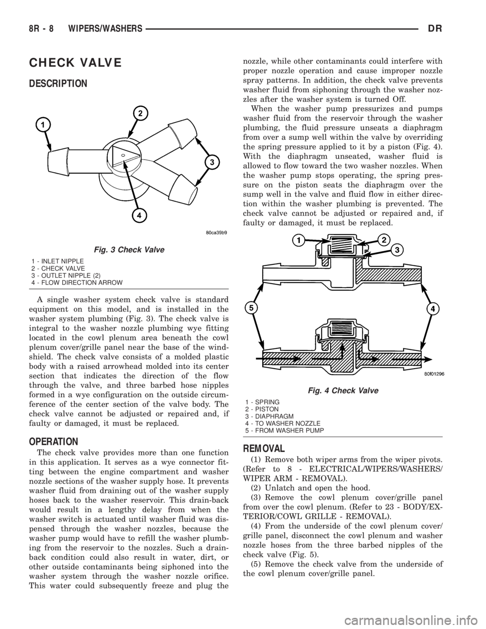
A single washer system check valve is standard
equipment on this model, and is installed in the
washer system plumbing (Fig. 3). The check valve is
integral to the washer nozzle plumbing wye fitting
located in the cowl plenum area beneath the cowl
plenum cover/grille panel near the base of the wind-
shield. The check valve consists of a molded plastic
body with a raised arrowhead molded into its center
section that indicates the direction of the flow
through the valve, and three barbed hose nipples
formed in a wye configuration on the outside circum-
ference of the center section of the valve body. The
check valve cannot be adjusted or repaired and, if
faulty or damaged, it must be replaced.
OPERATION
The check valve provides more than one function
in this application. It serves as a wye connector fit-
ting between the engine compartment and washer
nozzle sections of the washer supply hose. It prevents
washer fluid from draining out of the washer supply
hoses back to the washer reservoir. This drain-back
would result in a lengthy delay from when the
washer switch is actuated until washer fluid was dis-
pensed through the washer nozzles, because the
washer pump would have to refill the washer plumb-
ing from the reservoir to the nozzles. Such a drain-
back condition could also result in water, dirt, or
other outside contaminants being siphoned into the
washer system through the washer nozzle orifice.
This water could subsequently freeze and plug thenozzle, while other contaminants could interfere with
proper nozzle operation and cause improper nozzle
spray patterns. In addition, the check valve prevents
washer fluid from siphoning through the washer noz-
zles after the washer system is turned Off.
When the washer pump pressurizes and pumps
washer fluid from the reservoir through the washer
plumbing, the fluid pressure unseats a diaphragm
from over a sump well within the valve by overriding
the spring pressure applied to it by a piston (Fig. 4).
With the diaphragm unseated, washer fluid is
allowed to flow toward the two washer nozzles. When
the washer pump stops operating, the spring pres-
sure on the piston seats the diaphragm over the
sump well in the valve and fluid flow in either direc-
tion within the washer plumbing is prevented. The
check valve cannot be adjusted or repaired and, if
faulty or damaged, it must be replaced.REMOVAL
(1) Remove both wiper arms from the wiper pivots.
(Refer to 8 - ELECTRICAL/WIPERS/WASHERS/
WIPER ARM - REMOVAL).
(2) Unlatch and open the hood.
(3) Remove the cowl plenum cover/grille panel
from over the cowl plenum. (Refer to 23 - BODY/EX-
TERIOR/COWL GRILLE - REMOVAL).
(4) From the underside of the cowl plenum cover/
grille panel, disconnect the cowl plenum and washer
nozzle hoses from the three barbed nipples of the
check valve (Fig. 5).
(5) Remove the check valve from the underside of
the cowl plenum cover/grille panel.
Fig. 3 Check Valve
1 - INLET NIPPLE
2 - CHECK VALVE
3 - OUTLET NIPPLE (2)
4 - FLOW DIRECTION ARROW
Fig. 4 Check Valve
1 - SPRING
2 - PISTON
3 - DIAPHRAGM
4 - TO WASHER NOZZLE
5 - FROM WASHER PUMP
8R - 8 WIPERS/WASHERSDR
Page 684 of 2895
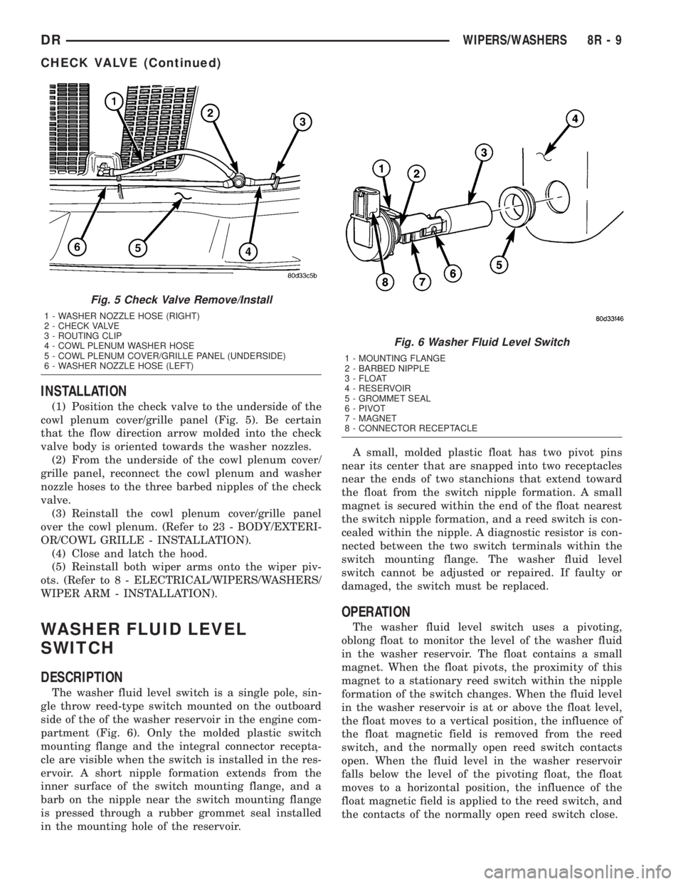
INSTALLATION
(1) Position the check valve to the underside of the
cowl plenum cover/grille panel (Fig. 5). Be certain
that the flow direction arrow molded into the check
valve body is oriented towards the washer nozzles.
(2) From the underside of the cowl plenum cover/
grille panel, reconnect the cowl plenum and washer
nozzle hoses to the three barbed nipples of the check
valve.
(3) Reinstall the cowl plenum cover/grille panel
over the cowl plenum. (Refer to 23 - BODY/EXTERI-
OR/COWL GRILLE - INSTALLATION).
(4) Close and latch the hood.
(5) Reinstall both wiper arms onto the wiper piv-
ots. (Refer to 8 - ELECTRICAL/WIPERS/WASHERS/
WIPER ARM - INSTALLATION).
WASHER FLUID LEVEL
SWITCH
DESCRIPTION
The washer fluid level switch is a single pole, sin-
gle throw reed-type switch mounted on the outboard
side of the of the washer reservoir in the engine com-
partment (Fig. 6). Only the molded plastic switch
mounting flange and the integral connector recepta-
cle are visible when the switch is installed in the res-
ervoir. A short nipple formation extends from the
inner surface of the switch mounting flange, and a
barb on the nipple near the switch mounting flange
is pressed through a rubber grommet seal installed
in the mounting hole of the reservoir.A small, molded plastic float has two pivot pins
near its center that are snapped into two receptacles
near the ends of two stanchions that extend toward
the float from the switch nipple formation. A small
magnet is secured within the end of the float nearest
the switch nipple formation, and a reed switch is con-
cealed within the nipple. A diagnostic resistor is con-
nected between the two switch terminals within the
switch mounting flange. The washer fluid level
switch cannot be adjusted or repaired. If faulty or
damaged, the switch must be replaced.
OPERATION
The washer fluid level switch uses a pivoting,
oblong float to monitor the level of the washer fluid
in the washer reservoir. The float contains a small
magnet. When the float pivots, the proximity of this
magnet to a stationary reed switch within the nipple
formation of the switch changes. When the fluid level
in the washer reservoir is at or above the float level,
the float moves to a vertical position, the influence of
the float magnetic field is removed from the reed
switch, and the normally open reed switch contacts
open. When the fluid level in the washer reservoir
falls below the level of the pivoting float, the float
moves to a horizontal position, the influence of the
float magnetic field is applied to the reed switch, and
the contacts of the normally open reed switch close.
Fig. 5 Check Valve Remove/Install
1 - WASHER NOZZLE HOSE (RIGHT)
2 - CHECK VALVE
3 - ROUTING CLIP
4 - COWL PLENUM WASHER HOSE
5 - COWL PLENUM COVER/GRILLE PANEL (UNDERSIDE)
6 - WASHER NOZZLE HOSE (LEFT)
Fig. 6 Washer Fluid Level Switch
1 - MOUNTING FLANGE
2 - BARBED NIPPLE
3 - FLOAT
4 - RESERVOIR
5 - GROMMET SEAL
6 - PIVOT
7 - MAGNET
8 - CONNECTOR RECEPTACLE
DRWIPERS/WASHERS 8R - 9
CHECK VALVE (Continued)
Page 685 of 2895
The washer fluid level switch is connected to the
vehicle electrical system through a dedicated take
out and connector of the right (except V-10 and diesel
engines) or left (V-10 and diesel engines only) head-
lamp and dash wire harness. The switch is connected
in series between a clean ground output of the Front
Control Module (FCM) on a sensor return circuit and
the washer fluid switch sense input to the FCM.
When the switch closes, the FMC senses the ground
on the washer fluid switch sense circuit. The FMC is
programmed to respond to this input by sending an
electronic washer fluid indicator lamp-on message to
the instrument cluster over the Programmable Com-
munications Interface (PCI) data bus. The instru-
ment cluster responds to this message by
illuminating the washer fluid indicator and by sound-
ing an audible chime tone warning.
The washer fluid level switch may be diagnosed
and tested using conventional diagnostic tools and
procedures. However, conventional diagnostic meth-
ods may not prove conclusive in the diagnosis of the
instrument cluster, the Front Control Module (FCM),
or the electronic message inputs to or outputs from
the instrument cluster and the FCM that control the
operation of the washer fluid visual and/or audible
indicators. The most reliable, efficient, and accurate
means to diagnose the washer fluid level indicator,
the instrument cluster, the FCM, or the electronic
message inputs and outputs related to the washer
fluid indicator requires the use of a DRBIIItscan
tool. Refer to the appropriate diagnostic information.
REMOVAL
The washer fluid level switch can be removed from
the washer reservoir without removing the reservoir
from the vehicle.
(1) Unlatch and open the hood.
(2) Disconnect and isolate the battery negative
cable.
(3) Disconnect the washer hose from the barbed
outlet nipple of the washer pump/motor unit and
allow the washer fluid to drain into a clean container
for reuse.
(4) Disconnect the right (except V-10 and diesel
engine) or left (V-10 and diesel engine only) head-
lamp and dash wire harness connector for the washer
fluid level switch from the switch connector recepta-
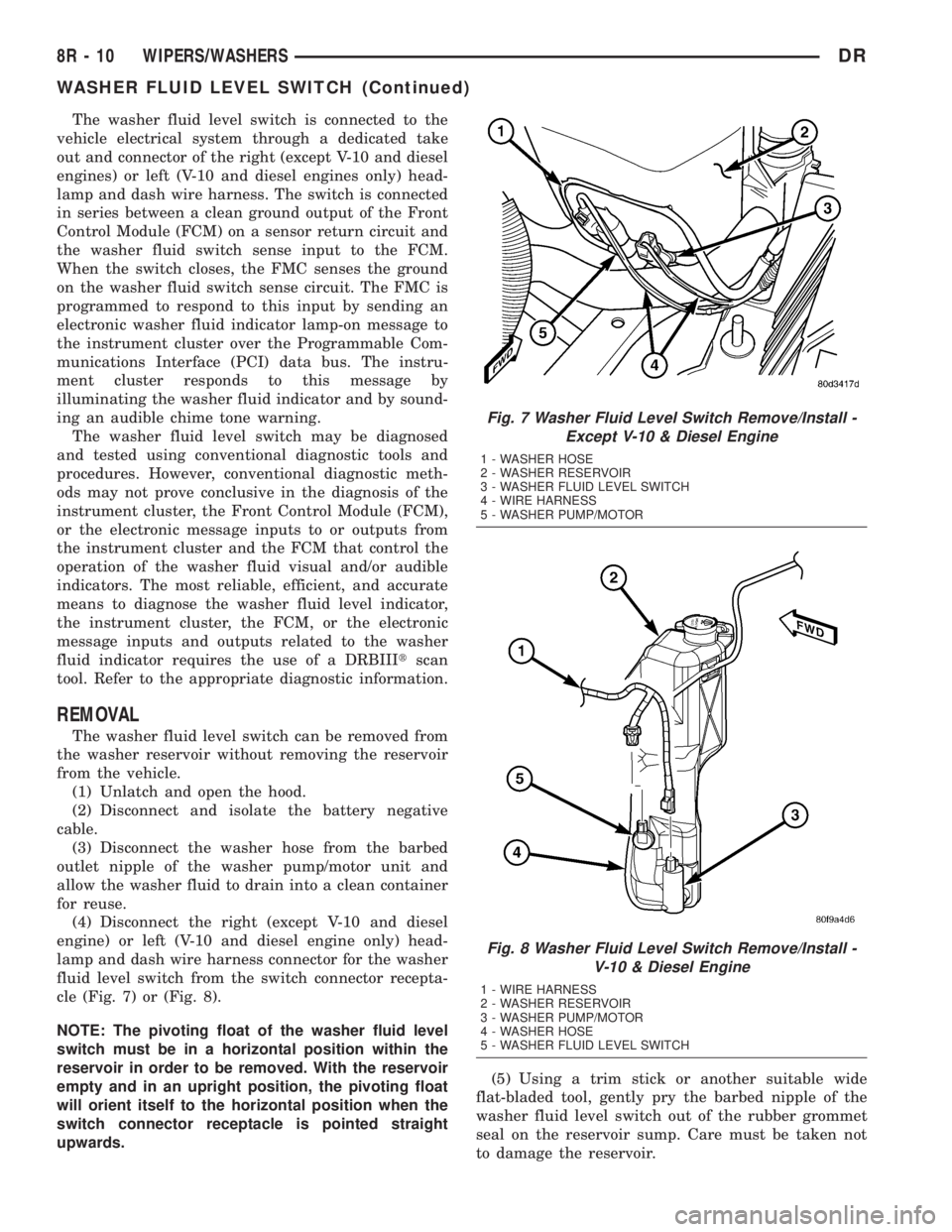
cle (Fig. 7) or (Fig. 8).
NOTE: The pivoting float of the washer fluid level
switch must be in a horizontal position within the
reservoir in order to be removed. With the reservoir
empty and in an upright position, the pivoting float
will orient itself to the horizontal position when the
switch connector receptacle is pointed straight
upwards.(5) Using a trim stick or another suitable wide
flat-bladed tool, gently pry the barbed nipple of the
washer fluid level switch out of the rubber grommet
seal on the reservoir sump. Care must be taken not
to damage the reservoir.
Fig. 7 Washer Fluid Level Switch Remove/Install -
Except V-10 & Diesel Engine
1 - WASHER HOSE
2 - WASHER RESERVOIR
3 - WASHER FLUID LEVEL SWITCH
4 - WIRE HARNESS
5 - WASHER PUMP/MOTOR
Fig. 8 Washer Fluid Level Switch Remove/Install -
V-10 & Diesel Engine
1 - WIRE HARNESS
2 - WASHER RESERVOIR
3 - WASHER PUMP/MOTOR
4 - WASHER HOSE
5 - WASHER FLUID LEVEL SWITCH
8R - 10 WIPERS/WASHERSDR
WASHER FLUID LEVEL SWITCH (Continued)