Ignition coil ground wire DODGE RAM 2003 Service Repair Manual
[x] Cancel search | Manufacturer: DODGE, Model Year: 2003, Model line: RAM, Model: DODGE RAM 2003Pages: 2895, PDF Size: 83.15 MB
Page 392 of 2895
OPERATION
OPERATION - PCM
The PCM operates the fuel system. The PCM is a
pre-programmed, triple microprocessor digital com-
puter. It regulates ignition timing, air-fuel ratio,
emission control devices, charging system, certain
transmission features, speed control, air conditioning
compressor clutch engagement and idle speed. The
PCM can adapt its programming to meet changing
operating conditions.
The PCM receives input signals from various
switches and sensors. Based on these inputs, the
PCM regulates various engine and vehicle operations
through different system components. These compo-
nents are referred to as Powertrain Control Module
(PCM) Outputs. The sensors and switches that pro-
vide inputs to the PCM are considered Powertrain
Control Module (PCM) Inputs.
The PCM adjusts ignition timing based upon
inputs it receives from sensors that react to: engine
rpm, manifold absolute pressure, engine coolant tem-
perature, throttle position, transmission gear selec-
tion (automatic transmission), vehicle speed, power
steering pump pressure, and the brake switch.
The PCM adjusts idle speed based on inputs it
receives from sensors that react to: throttle position,
vehicle speed, transmission gear selection, engine
coolant temperature and from inputs it receives from
the air conditioning clutch switch and brake switch.
Based on inputs that it receives, the PCM adjusts
ignition coil dwell. The PCM also adjusts the gener-
ator charge rate through control of the generator
field and provides speed control operation.
NOTE: PCM Inputs:
²ABS module (if equipped)
²A/C request (if equipped with factory A/C)
²A/C select (if equipped with factory A/C)
²A/C pressure transducer
²Auto shutdown (ASD) sense
²Battery temperature sensor
²Battery voltage
²Brake switch
²J1850 bus (+) circuits
²J1850 bus (-) circuits
²Camshaft position sensor signal
²Crankshaft position sensor
²Data link connection for DRB scan tool
²EATX module (if equipped)
²Engine coolant temperature sensor
²Fuel level (through J1850 circuitry)
²Generator (battery voltage) output
²Ignition circuit sense (ignition switch in on/off/
crank/run position)²Intake manifold air temperature sensor
²Knock sensors (2 on 3.7L engine)
²Leak detection pump (switch) sense (if equipped)
²Manifold absolute pressure (MAP) sensor
²Oil pressure
²Oxygen sensors
²Park/neutral switch (auto. trans. only)
²Power ground
²Power steering pressure switch (if equipped)
²Sensor return
²Signal ground
²Speed control multiplexed single wire input
²Throttle position sensor
²Transfer case switch (4WD range position)
²Vehicle speed signal
NOTE: PCM Outputs:
²A/C clutch relay
²Auto shutdown (ASD) relay
²J1850 bus (+/-) circuits for: speedometer, voltme-
ter, fuel gauge, oil pressure gauge/lamp, engine temp.
gauge and speed control warn. lamp
²Data link connection for DRB scan tool
²EGR valve control solenoid (if equipped)
²EVAP canister purge solenoid
²Five volt sensor supply (primary)
²Five volt sensor supply (secondary)
²Fuel injectors
²Fuel pump relay
²Generator field driver (-)
²Generator field driver (+)
²Idle air control (IAC) motor
²Ignition coil(s)
²Leak detection pump (if equipped)
²Malfunction indicator lamp (Check engine lamp).
Driven through J1850 circuits.
²Oxygen sensor heater relays
²Oxygen sensors (pulse width modulated)
²Radiator cooling fan relay (pulse width modu-
lated)
²Speed control vacuum solenoid
²Speed control vent solenoid
²Tachometer (if equipped). Driven through J1850
circuits.
²Transmission convertor clutch circuit. Driven
through J1850 circuits.
OPERATION - 5 VOLT SUPPLIES
Primary 5±volt supply:
²supplies the required 5 volt power source to the
Crankshaft Position (CKP) sensor.
²supplies the required 5 volt power source to the
Camshaft Position (CMP) sensor.
²supplies a reference voltage for the Manifold
Absolute Pressure (MAP) sensor.
DRELECTRONIC CONTROL MODULES 8E - 11
POWERTRAIN CONTROL MODULE (Continued)
Page 433 of 2895
STARTING
TABLE OF CONTENTS
page page
STARTING
DESCRIPTION.........................28
OPERATION...........................28
DIAGNOSIS AND TESTING - STARTING
SYSTEM............................29
SPECIFICATIONS
STARTING SYSTEM...................33
SPECIFICATIONS - TORQUE - STARTING
SYSTEM............................34
STARTER MOTOR
DIAGNOSIS AND TESTING - STARTER
MOTOR .............................34REMOVAL.............................34
INSTALLATION.........................37
STARTER MOTOR RELAY
DESCRIPTION.........................38
OPERATION...........................38
DIAGNOSIS AND TESTING - STARTER RELAY . 38
REMOVAL.............................39
INSTALLATION.........................39
STARTING
DESCRIPTION
The starting system consists of:
²Starter relay
²Starter motor (including an integral starter sole-
noid)
Other components to be considered as part of start-
ing system are:
²Battery
²Battery cables
²Ignition switch and key lock cylinder
²Clutch pedal position switch (manual transmis-
sion)
²Park/neutral position switch (automatic trans-
mission)
²Wire harnesses and connections.
The Battery, Starting, and Charging systems oper-
ate in conjunction with one another, and must be
tested as a complete system. For correct operation of
starting/charging systems, all components used in
these 3 systems must perform within specifications.
When attempting to diagnose any of these systems, it
is important that you keep their interdependency in
mind.
The diagnostic procedures used in each of these
groups include the most basic conventional diagnostic
methods, to the more sophisticated On-Board Diag-
nostics (OBD) built into the Powertrain Control Mod-
ule (PCM). Use of an induction-type milliampere
ammeter, volt/ohmmeter, battery charger, carbon pile
rheostat (load tester), and 12-volt test lamp may be
required.
Certain starting system components are monitored
by the PCM and may produce a Diagnostic TroubleCode (DTC). Refer to Diagnostic Trouble Codes in
Emission Control for a list of codes.OPERATION
The starting system components form two separate
circuits. A high-amperage feed circuit that feeds the
starter motor between 150 and 350 amperes (700
amperes - diesel engine), and a low-amperage control
circuit that operates on less than 20 amperes. The
high-amperage feed circuit components include the
battery, the battery cables, the contact disc portion of
the starter solenoid, and the starter motor. The low-
amperage control circuit components include the igni-
tion switch, the clutch pedal position switch (manual
transmission), the park/neutral position switch (auto-
matic transmission), the starter relay, the electro-
magnetic windings of the starter solenoid, and the
connecting wire harness components.
If the vehicle is equipped with a manual transmis-
sion, it has a clutch pedal position switch installed in
series between the ignition switch and the coil bat-
tery terminal of the starter relay. This normally open
switch prevents the starter relay from being ener-
gized when the ignition switch is turned to the Start
position, unless the clutch pedal is depressed. This
feature prevents starter motor operation while the
clutch disc and the flywheel are engaged. The starter
relay coil ground terminal is always grounded on
vehicles with a manual transmission.
If the vehicle is equipped with an automatic trans-
mission, battery voltage is supplied through the low-
amperage control circuit to the coil battery terminal
of the starter relay when the ignition switch is
turned to the Start position. The park/neutral posi-
tion switch is installed in series between the starter
relay coil ground terminal and ground. This normally
8F - 28 STARTINGDR
Page 464 of 2895
DIAGNOSIS AND TESTING - ASD AND FUEL
PUMP RELAYS
The following description of operation and
tests apply only to the Automatic Shutdown
(ASD) and fuel pump relays. The terminals on the
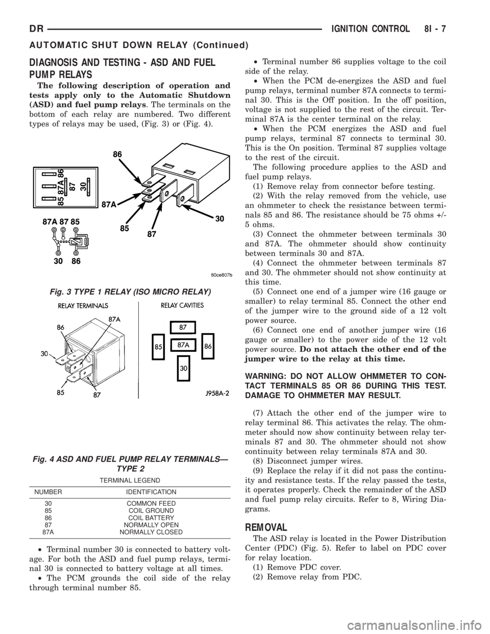
bottom of each relay are numbered. Two different
types of relays may be used, (Fig. 3) or (Fig. 4).
²Terminal number 30 is connected to battery volt-
age. For both the ASD and fuel pump relays, termi-
nal 30 is connected to battery voltage at all times.
²The PCM grounds the coil side of the relay
through terminal number 85.²Terminal number 86 supplies voltage to the coil
side of the relay.
²When the PCM de-energizes the ASD and fuel
pump relays, terminal number 87A connects to termi-
nal 30. This is the Off position. In the off position,
voltage is not supplied to the rest of the circuit. Ter-
minal 87A is the center terminal on the relay.
²When the PCM energizes the ASD and fuel
pump relays, terminal 87 connects to terminal 30.
This is the On position. Terminal 87 supplies voltage
to the rest of the circuit.
The following procedure applies to the ASD and
fuel pump relays.
(1) Remove relay from connector before testing.
(2) With the relay removed from the vehicle, use
an ohmmeter to check the resistance between termi-
nals 85 and 86. The resistance should be 75 ohms +/-
5 ohms.
(3) Connect the ohmmeter between terminals 30
and 87A. The ohmmeter should show continuity
between terminals 30 and 87A.
(4) Connect the ohmmeter between terminals 87
and 30. The ohmmeter should not show continuity at
this time.
(5) Connect one end of a jumper wire (16 gauge or
smaller) to relay terminal 85. Connect the other end
of the jumper wire to the ground side of a 12 volt
power source.
(6) Connect one end of another jumper wire (16
gauge or smaller) to the power side of the 12 volt
power source.Do not attach the other end of the
jumper wire to the relay at this time.
WARNING: DO NOT ALLOW OHMMETER TO CON-
TACT TERMINALS 85 OR 86 DURING THIS TEST.
DAMAGE TO OHMMETER MAY RESULT.
(7) Attach the other end of the jumper wire to
relay terminal 86. This activates the relay. The ohm-
meter should now show continuity between relay ter-
minals 87 and 30. The ohmmeter should not show
continuity between relay terminals 87A and 30.
(8) Disconnect jumper wires.
(9) Replace the relay if it did not pass the continu-
ity and resistance tests. If the relay passed the tests,
it operates properly. Check the remainder of the ASD
and fuel pump relay circuits. Refer to 8, Wiring Dia-
grams.
REMOVAL
The ASD relay is located in the Power Distribution
Center (PDC) (Fig. 5). Refer to label on PDC cover
for relay location.
(1) Remove PDC cover.
(2) Remove relay from PDC.
Fig. 3 TYPE 1 RELAY (ISO MICRO RELAY)
Fig. 4 ASD AND FUEL PUMP RELAY TERMINALSÐ
TYPE 2
TERMINAL LEGEND
NUMBER IDENTIFICATION
30 COMMON FEED
85 COIL GROUND
86 COIL BATTERY
87 NORMALLY OPEN
87A NORMALLY CLOSED
DRIGNITION CONTROL 8I - 7
AUTOMATIC SHUT DOWN RELAY (Continued)
Page 490 of 2895
IGNITION COIL CAPACITOR
DESCRIPTION
One coil capacitor is used. It is located in the right-
rear section of the engine compartment.
OPERATION
The coil capacitor(s) help dampen the amount of
conducted electrical noise to the camshaft position
sensor, crankshaft position sensor, and throttle posi-
tion sensor. This noise is generated on the 12V sup-
ply wire to the ignition coils and fuel injectors.
REMOVAL
The coil capacitor is located in the right-rear sec-
tion of the engine compartment. It is attached with a
mounting stud and nut.
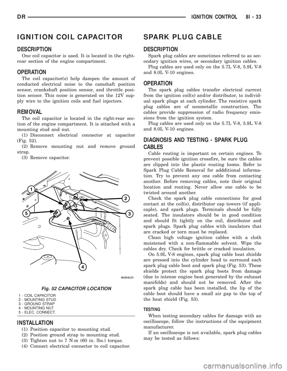
(1) Disconnect electrical connector at capacitor
(Fig. 52).
(2) Remove mounting nut and remove ground
strap.
(3) Remove capacitor.
INSTALLATION
(1) Position capacitor to mounting stud.
(2) Position ground strap to mounting stud.
(3) Tighten nut to 7 N´m (60 in. lbs.) torque.
(4) Connect electrical connector to coil capacitor.
SPARK PLUG CABLE
DESCRIPTION
Spark plug cables are sometimes referred to as sec-
ondary ignition wires, or secondary ignition cables.
Plug cables are used only on the 5.7L V-8, 5.9L V-8
and 8.0L V-10 engines.
OPERATION
The spark plug cables transfer electrical current
from the ignition coil(s) and/or distributor, to individ-
ual spark plugs at each cylinder. The resistive spark
plug cables are of nonmetallic construction. The
cables provide suppression of radio frequency emis-
sions from the ignition system.
Plug cables are used only on the 5.7L V-8, 5.9L V-8
and 8.0L V-10 engines.
DIAGNOSIS AND TESTING - SPARK PLUG
CABLES
Cable routing is important on certain engines. To
prevent possible ignition crossfire, be sure the cables
are clipped into the plastic routing looms. Refer to
Spark Plug Cable Removal for addditional informa-
tion. Try to prevent any one cable from contacting
another. Before removing cables, note their original
location and routing. Never allow one cable to be
twisted around another.
Check the spark plug cable connections for good
contact at the coil(s), distributor cap towers (if appli-
caple), and spark plugs. Terminals should be fully
seated. The insulators should be in good condition
and should fit tightly on the coil, distributor and
spark plugs. Spark plug cables with insulators that
are cracked or torn must be replaced.
Clean high voltage ignition cables with a cloth
moistened with a non-flammable solvent. Wipe the
cables dry. Check for brittle or cracked insulation.
On 5.9L V-8 engines, spark plug cable heat shields
are pressed into the cylinder head to surround each
spark plug cable boot and spark plug (Fig. 53). These
shields protect the spark plug boots from damage
(due to intense engine heat generated by the exhaust
manifolds) and should not be removed. After the
spark plug cable has been installed, the lip of the
cable boot should have a small air gap to the top of
the heat shield (Fig. 53).
TESTING
When testing secondary cables for damage with an
oscilloscope, follow the instructions of the equipment
manufacturer.
If an oscilloscope is not available, spark plug cables
may be tested as follows:
Fig. 52 CAPACITOR LOCATION
1 - COIL CAPACITOR
2 - MOUNTING STUD
3 - GROUND STRAP
4 - MOUNTING NUT
5 - ELEC. CONNECT.
DRIGNITION CONTROL 8I - 33
Page 650 of 2895
outboard seat belt and retractor unit must be
replaced. (Refer to 8 - ELECTRICAL/RESTRAINTS/
FRONT OUTBOARD SEAT BELT & RETRACTOR -
REMOVAL).
OPERATION
The seat belt tension reducer is controlled by a
ground signal received from the seat belt switch on
the seat belt switch sense circuit and a battery cur-
rent signal received from the ignition switch on the
fused ignition switch output (run-accessory) circuit.
When the seat belt switch is closed (the driver side
front seat belt is fastened) and the ignition switch is
in the On or Accessory positions, the seat belt tension
reducer solenoid is energized. When the solenoid is
energized, it actuates a mechanism within the driver
side front outboard seat belt retractor to reduce the
normal recoil spring tension exerted by the retractor
spool, which is designed to reel in the seat belt web-
bing onto the spool. When the driver side seat belt is
unbuckled or if the ignition switch is turned to any
position except On or Accessory, the tension reducer
solenoid is de-energized and the normal recoil spring
tension of the retractor is restored.
The action of the seat belt tension reducer results
in improved seat belt comfort for the driver. Reducing
the seat belt retractor recoil spring tension is desir-
able on standard cab models of this vehicle and not
on the quad cab model due to the different mounting
position required for the seat belt turning loop on the
B-pillar relative to the driver's seat position on the
standard cab model. The seat belt tension reducer
may be diagnosed using conventional diagnostic tools
and methods.
DIAGNOSIS AND TESTING - SEAT BELT
TENSION REDUCER
Refer to the appropriate wiring information. The
wiring information includes wiring diagrams, proper
wire and connector repair procedures, details of wire
harness routing and retention, connector pin-out
information and location views for the various wire
harness connectors, splices and grounds.
WARNING: ON VEHICLES EQUIPPED WITH AIR-
BAGS, DISABLE THE SUPPLEMENTAL RESTRAINTSYSTEM BEFORE ATTEMPTING ANY STEERING
WHEEL, STEERING COLUMN, DRIVER AIRBAG,
PASSENGER AIRBAG, SEAT BELT TENSIONER,
SIDE CURTAIN AIRBAG, OR INSTRUMENT PANEL
COMPONENT DIAGNOSIS OR SERVICE. DISCON-
NECT AND ISOLATE THE BATTERY NEGATIVE
(GROUND) CABLE, THEN WAIT TWO MINUTES FOR
THE SYSTEM CAPACITOR TO DISCHARGE BEFORE
PERFORMING FURTHER DIAGNOSIS OR SERVICE.
THIS IS THE ONLY SURE WAY TO DISABLE THE
SUPPLEMENTAL RESTRAINT SYSTEM. FAILURE TO
TAKE THE PROPER PRECAUTIONS COULD
RESULT IN ACCIDENTAL AIRBAG DEPLOYMENT
AND POSSIBLE PERSONAL INJURY.
(1) Disconnect and isolate the battery negative
cable. Disconnect the body wire harness connector for
the seat belt tension reducer from the tension
reducer connector receptacle on the driver side front
outboard seat belt and retractor unit. Using an ohm-
meter, measure the resistance between the seat belt
switch sense circuit terminal pin and the fused igni-
tion switch output (run-accessory) circuit terminal
pin in the tension reducer connector receptacle on
the retractor. Resistance through the tension reducer
solenoid coil should be 53 ohms at 20É C (68É F). If
OK, go to Step 2. If not OK, replace the faulty driver
side front outboard seat belt and retractor unit.
(2) Check for continuity between the seat belt
switch sense circuit cavity of the body wire harness
connector for the seat belt tension reducer and a good
ground. There should be continuity with the driver
side front seat belt buckled, and no continuity with
the driver side front seat belt unbuckled. If OK, go to
Step 3. If not OK, repair the shorted or open seat
belt switch sense circuit between the tension reducer
and the seat belt switch as required.
(3) Reconnect the battery negative cable. Check for
battery current at the fused ignition switch output
(run-accessory) circuit of the body wire harness con-
nector for the seat belt tension reducer. There should
be battery current with the ignition switch in the On
or Accessory positions, and no battery current with
the ignition switch in any other position. If not OK,
repair the shorted or open fused ignition switch out-
put (run-accessory) circuit between the tension
reducer and the ignition switch as required.
DRRESTRAINTS 8O - 49
SEAT BELT TENSION REDUCER (Continued)
Page 696 of 2895
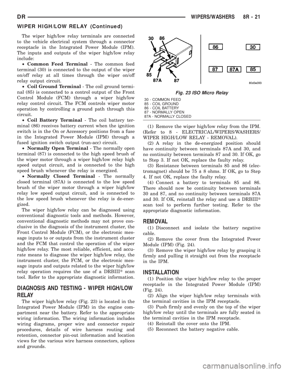
The wiper high/low relay terminals are connected
to the vehicle electrical system through a connector
receptacle in the Integrated Power Module (IPM).
The inputs and outputs of the wiper high/low relay
include:
²Common Feed Terminal- The common feed
terminal (30) is connected to the output of the wiper
on/off relay at all times through the wiper on/off
relay output circuit.
²Coil Ground Terminal- The coil ground termi-
nal (85) is connected to a control output of the Front
Control Module (FCM) through a wiper high/low
relay control circuit. The FCM controls wiper motor
operation by controlling a ground path through this
circuit.
²Coil Battery Terminal- The coil battery ter-
minal (86) receives battery current when the ignition
switch is in the On or Accessory positions from a fuse
in the Integrated Power Module (IPM) through a
fused ignition switch output (run-acc) circuit.
²Normally Open Terminal- The normally open
terminal (87) is connected to the high speed brush of
the wiper motor through a wiper high/low relay high
speed output circuit, and is connected to the high
speed brush whenever the relay is energized.
²Normally Closed Terminal- The normally
closed terminal (87A) is connected to the low speed
brush of the wiper motor through a wiper high/low
relay low speed output circuit, and is connected to
the low speed brush whenever the relay is de-ener-
gized.
The wiper high/low relay can be diagnosed using
conventional diagnostic tools and methods. However,
conventional diagnostic methods may not prove con-
clusive in the diagnosis of the instrument cluster, the
Front Control Module (FCM), or the electronic mes-
sage inputs to or outputs from the instrument cluster
and the FCM that control the operation of the wiper
high/low relay. The most reliable, efficient, and accu-
rate means to diagnose the wiper high/low relay, the
instrument cluster, the FCM, or the electronic mes-
sage inputs and outputs related to the wiper high/low
relay operation requires the use of a DRBIIItscan
tool. Refer to the appropriate diagnostic information.
DIAGNOSIS AND TESTING - WIPER HIGH/LOW
RELAY
The wiper high/low relay (Fig. 23) is located in the
Integrated Power Module (IPM) in the engine com-
partment near the battery. Refer to the appropriate
wiring information. The wiring information includes
wiring diagrams, proper wire and connector repair
procedures, details of wire harness routing and
retention, connector pin-out information and location
views for the various wire harness connectors, splices
and grounds.(1) Remove the wiper high/low relay from the IPM.
(Refer to 8 - ELECTRICAL/WIPERS/WASHERS/
WIPER HIGH/LOW RELAY - REMOVAL).
(2) A relay in the de-energized position should
have continuity between terminals 87A and 30, and
no continuity between terminals 87 and 30. If OK, go
to Step 3. If not OK, replace the faulty relay.
(3) Resistance between terminals 85 and 86 (elec-
tromagnet) should be 75 8 ohms. If OK, go to Step
4. If not OK, replace the faulty relay.
(4) Connect a battery to terminals 85 and 86.
There should now be continuity between terminals
30 and 87, and no continuity between terminals 87A
and 30. If OK, reinstall the relay and use a DRBIIIt
scan tool to perform further testing. Refer to the
appropriate diagnostic information.
REMOVAL
(1) Disconnect and isolate the battery negative
cable.
(2) Remove the cover from the Integrated Power
Module (IPM) (Fig. 24).
(3) Remove the wiper high/low relay by grasping it
firmly and pulling it straight out from the receptacle
in the IPM.
INSTALLATION
(1) Position the wiper high/low relay to the proper
receptacle in the Integrated Power Module (IPM)
(Fig. 24).
(2) Align the wiper high/low relay terminals with
the terminal cavities in the IPM receptacle.
(3) Push firmly and evenly on the top of the wiper
high/low relay until the terminals are fully seated in
the terminal cavities in the IPM receptacle.
(4) Reinstall the cover onto the IPM.
(5) Reconnect the battery negative cable.
Fig. 23 ISO Micro Relay
30 - COMMON FEED
85 - COIL GROUND
86 - COIL BATTERY
87 - NORMALLY OPEN
87A - NORMALLY CLOSED
DRWIPERS/WASHERS 8R - 21
WIPER HIGH/LOW RELAY (Continued)
Page 700 of 2895
WIPER ON/OFF RELAY
DESCRIPTION
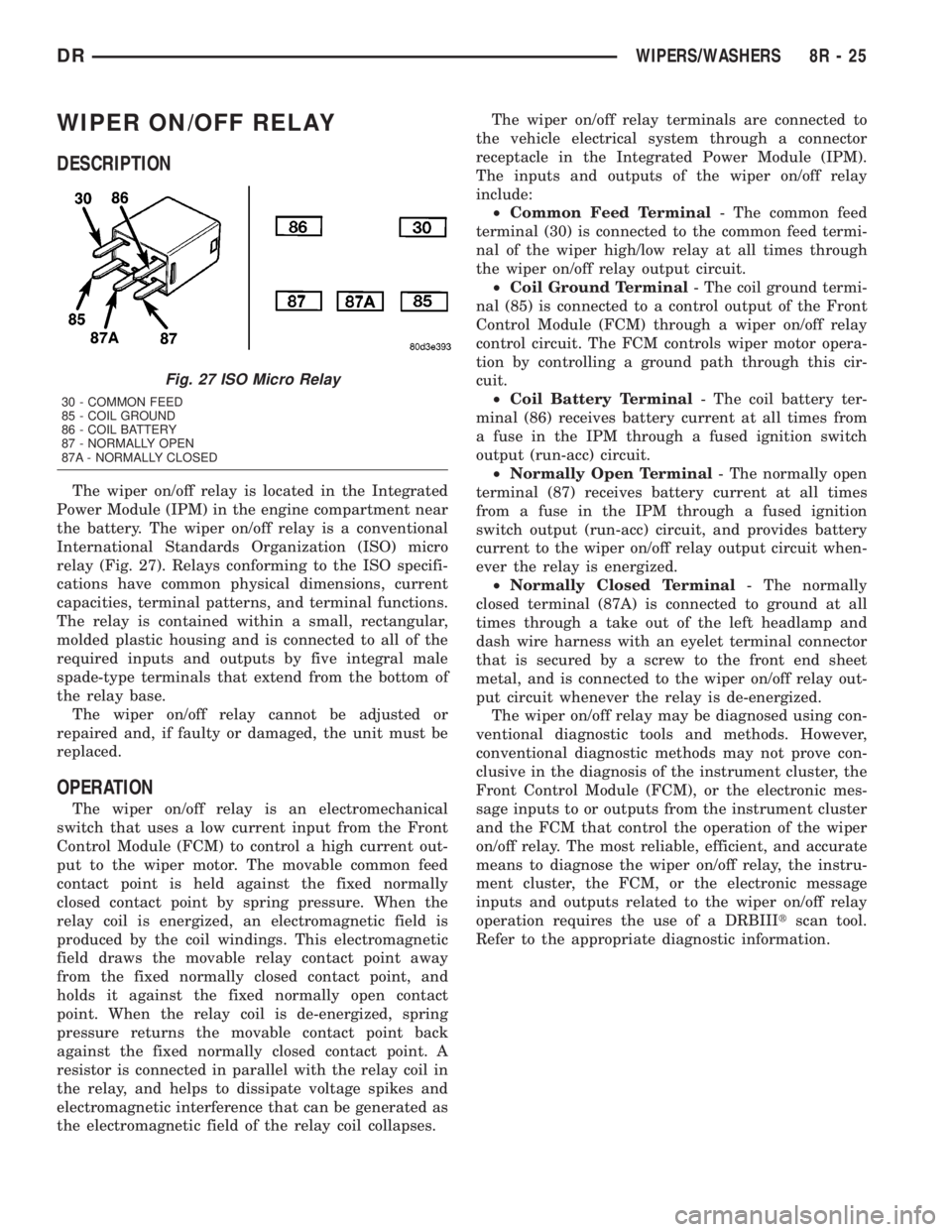
The wiper on/off relay is located in the Integrated
Power Module (IPM) in the engine compartment near
the battery. The wiper on/off relay is a conventional
International Standards Organization (ISO) micro
relay (Fig. 27). Relays conforming to the ISO specifi-
cations have common physical dimensions, current
capacities, terminal patterns, and terminal functions.
The relay is contained within a small, rectangular,
molded plastic housing and is connected to all of the
required inputs and outputs by five integral male
spade-type terminals that extend from the bottom of
the relay base.
The wiper on/off relay cannot be adjusted or
repaired and, if faulty or damaged, the unit must be
replaced.
OPERATION
The wiper on/off relay is an electromechanical
switch that uses a low current input from the Front
Control Module (FCM) to control a high current out-
put to the wiper motor. The movable common feed
contact point is held against the fixed normally
closed contact point by spring pressure. When the
relay coil is energized, an electromagnetic field is
produced by the coil windings. This electromagnetic
field draws the movable relay contact point away
from the fixed normally closed contact point, and
holds it against the fixed normally open contact
point. When the relay coil is de-energized, spring
pressure returns the movable contact point back
against the fixed normally closed contact point. A
resistor is connected in parallel with the relay coil in
the relay, and helps to dissipate voltage spikes and
electromagnetic interference that can be generated as
the electromagnetic field of the relay coil collapses.The wiper on/off relay terminals are connected to
the vehicle electrical system through a connector
receptacle in the Integrated Power Module (IPM).
The inputs and outputs of the wiper on/off relay
include:
²Common Feed Terminal- The common feed
terminal (30) is connected to the common feed termi-
nal of the wiper high/low relay at all times through
the wiper on/off relay output circuit.
²Coil Ground Terminal- The coil ground termi-
nal (85) is connected to a control output of the Front
Control Module (FCM) through a wiper on/off relay
control circuit. The FCM controls wiper motor opera-
tion by controlling a ground path through this cir-
cuit.
²Coil Battery Terminal- The coil battery ter-
minal (86) receives battery current at all times from
a fuse in the IPM through a fused ignition switch
output (run-acc) circuit.
²Normally Open Terminal- The normally open
terminal (87) receives battery current at all times
from a fuse in the IPM through a fused ignition
switch output (run-acc) circuit, and provides battery
current to the wiper on/off relay output circuit when-
ever the relay is energized.
²Normally Closed Terminal- The normally
closed terminal (87A) is connected to ground at all
times through a take out of the left headlamp and
dash wire harness with an eyelet terminal connector
that is secured by a screw to the front end sheet
metal, and is connected to the wiper on/off relay out-
put circuit whenever the relay is de-energized.
The wiper on/off relay may be diagnosed using con-
ventional diagnostic tools and methods. However,
conventional diagnostic methods may not prove con-
clusive in the diagnosis of the instrument cluster, the
Front Control Module (FCM), or the electronic mes-
sage inputs to or outputs from the instrument cluster
and the FCM that control the operation of the wiper
on/off relay. The most reliable, efficient, and accurate
means to diagnose the wiper on/off relay, the instru-
ment cluster, the FCM, or the electronic message
inputs and outputs related to the wiper on/off relay
operation requires the use of a DRBIIItscan tool.
Refer to the appropriate diagnostic information.
Fig. 27 ISO Micro Relay
30 - COMMON FEED
85 - COIL GROUND
86 - COIL BATTERY
87 - NORMALLY OPEN
87A - NORMALLY CLOSED
DRWIPERS/WASHERS 8R - 25
Page 1241 of 2895
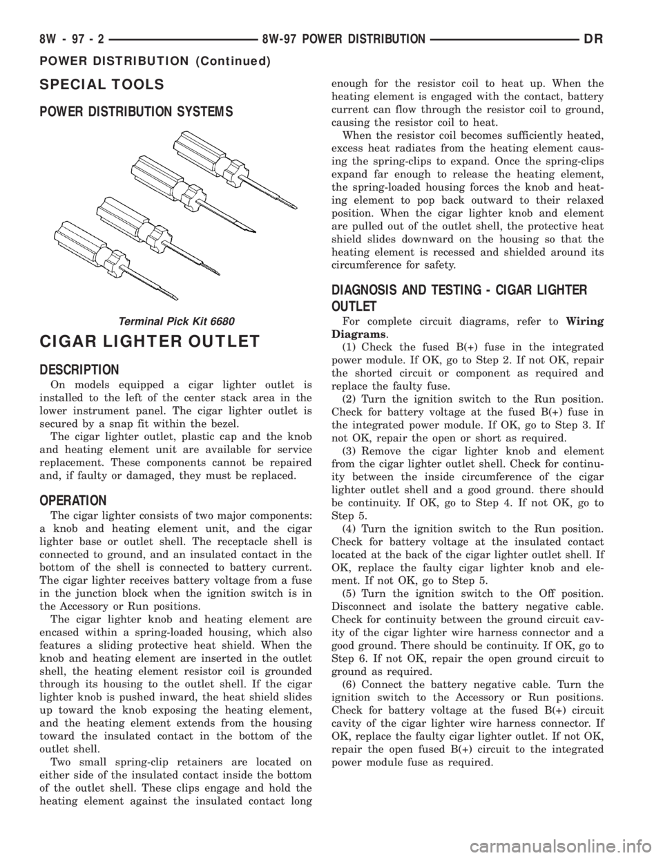
SPECIAL TOOLS
POWER DISTRIBUTION SYSTEMS
CIGAR LIGHTER OUTLET
DESCRIPTION
On models equipped a cigar lighter outlet is
installed to the left of the center stack area in the
lower instrument panel. The cigar lighter outlet is
secured by a snap fit within the bezel.
The cigar lighter outlet, plastic cap and the knob
and heating element unit are available for service
replacement. These components cannot be repaired
and, if faulty or damaged, they must be replaced.
OPERATION
The cigar lighter consists of two major components:
a knob and heating element unit, and the cigar
lighter base or outlet shell. The receptacle shell is
connected to ground, and an insulated contact in the
bottom of the shell is connected to battery current.
The cigar lighter receives battery voltage from a fuse
in the junction block when the ignition switch is in
the Accessory or Run positions.
The cigar lighter knob and heating element are
encased within a spring-loaded housing, which also
features a sliding protective heat shield. When the
knob and heating element are inserted in the outlet
shell, the heating element resistor coil is grounded
through its housing to the outlet shell. If the cigar
lighter knob is pushed inward, the heat shield slides
up toward the knob exposing the heating element,
and the heating element extends from the housing
toward the insulated contact in the bottom of the
outlet shell.
Two small spring-clip retainers are located on
either side of the insulated contact inside the bottom
of the outlet shell. These clips engage and hold the
heating element against the insulated contact longenough for the resistor coil to heat up. When the
heating element is engaged with the contact, battery
current can flow through the resistor coil to ground,
causing the resistor coil to heat.
When the resistor coil becomes sufficiently heated,
excess heat radiates from the heating element caus-
ing the spring-clips to expand. Once the spring-clips
expand far enough to release the heating element,
the spring-loaded housing forces the knob and heat-
ing element to pop back outward to their relaxed
position. When the cigar lighter knob and element
are pulled out of the outlet shell, the protective heat
shield slides downward on the housing so that the
heating element is recessed and shielded around its
circumference for safety.
DIAGNOSIS AND TESTING - CIGAR LIGHTER
OUTLET
For complete circuit diagrams, refer toWiring
Diagrams.
(1) Check the fused B(+) fuse in the integrated
power module. If OK, go to Step 2. If not OK, repair
the shorted circuit or component as required and
replace the faulty fuse.
(2) Turn the ignition switch to the Run position.
Check for battery voltage at the fused B(+) fuse in
the integrated power module. If OK, go to Step 3. If
not OK, repair the open or short as required.
(3) Remove the cigar lighter knob and element
from the cigar lighter outlet shell. Check for continu-
ity between the inside circumference of the cigar
lighter outlet shell and a good ground. there should
be continuity. If OK, go to Step 4. If not OK, go to
Step 5.
(4) Turn the ignition switch to the Run position.
Check for battery voltage at the insulated contact
located at the back of the cigar lighter outlet shell. If
OK, replace the faulty cigar lighter knob and ele-
ment. If not OK, go to Step 5.
(5) Turn the ignition switch to the Off position.
Disconnect and isolate the battery negative cable.
Check for continuity between the ground circuit cav-
ity of the cigar lighter wire harness connector and a
good ground. There should be continuity. If OK, go to
Step 6. If not OK, repair the open ground circuit to
ground as required.
(6) Connect the battery negative cable. Turn the
ignition switch to the Accessory or Run positions.
Check for battery voltage at the fused B(+) circuit
cavity of the cigar lighter wire harness connector. If
OK, replace the faulty cigar lighter outlet. If not OK,
repair the open fused B(+) circuit to the integrated
power module fuse as required.Terminal Pick Kit 6680
8W - 97 - 2 8W-97 POWER DISTRIBUTIONDR
POWER DISTRIBUTION (Continued)
Page 1445 of 2895
CAUTION: The head gaskets are marked ªTOPº to
indicate which side goes up.
(4) Position cylinder heads onto head gaskets and
cylinder block.
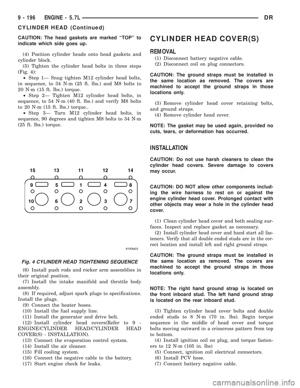
(5) Tighten the cylinder head bolts in three steps
(Fig. 4):
²Step 1Ð Snug tighten M12 cylinder head bolts,
in sequence, to 34 N´m (25 ft. lbs.) and M8 bolts to
20 N´m (15 ft. lbs.) torque.
²Step 2Ð Tighten M12 cylinder head bolts, in
sequence, to 54 N´m (40 ft. lbs.) and verify M8 bolts
to 20 N´m (15 ft. lbs.) torque..
²Step 3Ð Turn M12 cylinder head bolts, in
sequence, 90 degrees and tighten M8 bolts to 34 N´m
(25 ft. lbs.) torque.
(6) Install push rods and rocker arm assemblies in
their original position.
(7) Install the intake manifold and throttle body
assembly.
(8) If required, adjust spark plugs to specifications.
Install the plugs.
(9) Connect the heater hoses.
(10) Install the fuel supply line.
(11) Install the generator and drive belt.
(12) Install cylinder head covers(Refer to 9 -
ENGINE/CYLINDER HEAD/CYLINDER HEAD
COVER(S) - INSTALLATION).
(13) Connect the evaporation control system.
(14) Install the air cleaner.
(15) Fill cooling system.
(16) Connect the negative cable to the battery.
(17) Start engine check for leaks.CYLINDER HEAD COVER(S)
REMOVAL
(1) Disconnect battery negative cable.
(2) Disconnect coil on plug connectors.
CAUTION: The ground straps must be installed in
the same location as removed. The covers are
machined to accept the ground straps in those
locations only.
(3) Remove cylinder head cover retaining bolts,
and ground straps.
(4) Remove cylinder head cover.
NOTE: The gasket may be used again, provided no
cuts, tears, or deformation has occurred.
INSTALLATION
CAUTION: Do not use harsh cleaners to clean the
cylinder head covers. Severe damage to covers
may occur.
CAUTION: DO NOT allow other components includ-
ing the wire harness to rest on or against the
engine cylinder head cover. Prolonged contact with
other objects may wear a hole in the cylinder head
cover.
(1) Clean cylinder head cover and both sealing sur-
faces. Inspect and replace gasket as necessary.
(2)
Install cylinder head cover and hand start all fas-
teners. Verify that all double ended studs are in the cor-
rect location and install left and right ground straps.
CAUTION: The ground straps must be installed in
the same location as removed. The covers are
machined to accept the ground straps in those
locations only.
NOTE: The right hand ground strap is located on
the front inboard stud. The left hand ground strap
is located on the rear inboard stud.
(3) Tighten cylinder head cover bolts and double
ended studs to 8 N´m (70 in. lbs). Begin torque
sequence in the middle of head cover and torque
bolts moving outward in a crisscross pattern from top
to bottom.
(4) Install ignition coil on plug, and torque fasten-
ers to 12 N´m (105 in. lbs)
(5) Connect, ignition coil electrical connectors.
(6) Install PCV hose.
(7) Connect battery negative cable.
Fig. 4 CYLINDER HEAD TIGHTENING SEQUENCE
9 - 196 ENGINE - 5.7LDR
CYLINDER HEAD (Continued)
Page 2788 of 2895
NOTE: The air gap is determined by the spacer
shims. When installing an original, or a new clutch
assembly, try the original shims first. When install-
ing a new clutch onto a compressor that previously
did not have a clutch, use a 1.0, 0.50, and 0.13 mil-
limeter (0.040, 0.020, and 0.005 inch) shims from the
new clutch hardware package that is provided with
the new clutch.
(9) To complete the procedure, (Refer to 24 -
HEATING & AIR CONDITIONING/PLUMBING/A/C
COMPRESSOR - INSTALLATION).
A/C COMPRESSOR CLUTCH
RELAY
DESCRIPTION
The compressor clutch relay is a International
Standards Organization (ISO) micro-relay. The termi-
nal designations and functions are the same as a con-
ventional ISO relay. However, the micro-relay
terminal orientation (footprint) is different, the cur-
rent capacity is lower, and the relay case dimensions
are smaller than those of the conventional ISO relay.
The compressor clutch relay is located in the Power
Distribution Center (PDC) in the engine compart-
ment. Refer to the PDC label for relay identification
and location.
OPERATION
The compressor clutch relay is a electromechanical
device that switches battery current to the compres-
sor clutch coil when the Powertrain Control Module
(PCM) grounds the coil side of the relay. The PCM
responds to inputs from the A/C Heater mode control
switch, the A/C low pressure switch, and the A/C
high pressure switch. (Refer to 24 - HEATING & AIR
CONDITIONING/CONTROLS/A/C COMPRESSOR
CLUTCH RELAY - DIAGNOSIS AND TESTING)
The compressor clutch relay cannot be repaired
and, if faulty or damaged, it must be replaced.
DIAGNOSIS AND TESTING - COMPRESSOR
CLUTCH RELAY
RELAY TEST
The compressor clutch relay (Fig. 10) is located in
the Power Distribution Center (PDC). Refer to the
PDC label for relay identification and location.
Remove the relay from the PDC to perform the fol-
lowing tests:
(1) A relay in the de-energized position should
have continuity between terminals 87A and 30, and
no continuity between terminals 87 and 30. If OK, go
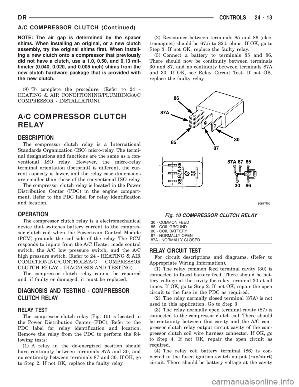
to Step 2. If not OK, replace the faulty relay.(2) Resistance between terminals 85 and 86 (elec-
tromagnet) should be 67.5 to 82.5 ohms. If OK, go to
Step 3. If not OK, replace the faulty relay.
(3) Connect a battery to terminals 85 and 86.
There should now be continuity between terminals
30 and 87, and no continuity between terminals 87A
and 30. If OK, see Relay Circuit Test. If not OK,
replace the faulty relay.
RELAY CIRCUIT TEST
For circuit descriptions and diagrams, (Refer to
Appropriate Wiring Information).
(1) The relay common feed terminal cavity (30) is
connected to fused battery feed. There should be bat-
tery voltage at the cavity for relay terminal 30 at all
times. If OK, go to Step 2. If not OK, repair the open
circuit to the fuse in the PDC as required.
(2) The relay normally closed terminal (87A) is not
used in this application. Go to Step 3.
(3) The relay normally open terminal cavity (87) is
connected to the compressor clutch coil. There should
be continuity between this cavity and the A/C com-
pressor clutch relay output circuit cavity of the com-
pressor clutch coil wire harness connector. If OK, go
to Step 4. If not OK, repair the open circuit as
required.
(4) The relay coil battery terminal (86) is con-
nected to the fused ignition switch output (run/start)
circuit. There should be battery voltage at the cavity
Fig. 10 COMPRESSOR CLUTCH RELAY
30 - COMMON FEED
85 - COIL GROUND
86 - COIL BATTERY
87 - NORMALLY OPEN
87A - NORMALLY CLOSED
DRCONTROLS 24 - 13
A/C COMPRESSOR CLUTCH (Continued)