Pcv valve DODGE RAM 2003 Service Repair Manual
[x] Cancel search | Manufacturer: DODGE, Model Year: 2003, Model line: RAM, Model: DODGE RAM 2003Pages: 2895, PDF Size: 83.15 MB
Page 20 of 2895
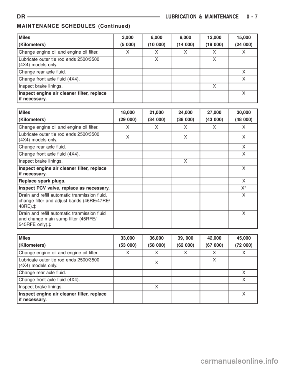
Miles 3,000 6,000 9,000 12,000 15,000
(Kilometers) (5 000) (10 000) (14 000) (19 000) (24 000)
Change engine oil and engine oil filter.XXXX X
Lubricate outer tie rod ends 2500/3500
(4X4) models only.XX
Change rear axle fluid.X
Change front axle fluid (4X4).X
Inspect brake linings.X
Inspect engine air cleaner filter, replace
if necessary.X
Miles 18,000 21,000 24,000 27,000 30,000
(Kilometers) (29 000) (34 000) (38 000) (43 000) (48 000)
Change engine oil and engine oil filter.XXXX X
Lubricate outer tie rod ends 2500/3500
(4X4) models only.XX X
Change rear axle fluid.X
Change front axle fluid (4X4).X
Inspect brake linings. X
Inspect engine air cleaner filter, replace
if necessary.X
Replace spark plugs.X
Inspect PCV valve, replace as necessary.X*
Drain and refill automatic tranmission fluid,
change filter and adjust bands (46RE/47RE/
48RE).³X
Drain and refill automatic tranmission fluid
and change main sump filter (45RFE/
545RFE only).³X
Miles 33,000 36,000 39, 000 42,000 45,000
(Kilometers) (53 000) (58 000) (62 000) (67 000) (72 000)
Change engine oil and engine oil filter.XXXX X
Lubricate outer tie rod ends 2500/3500
(4X4) models only.XX
Change rear axle fluid.X
Change front axle fluid (4X4).X
Inspect brake linings. X
Inspect engine air cleaner filter, replace
if necessary.X
DRLUBRICATION & MAINTENANCE 0 - 7
MAINTENANCE SCHEDULES (Continued)
Page 21 of 2895
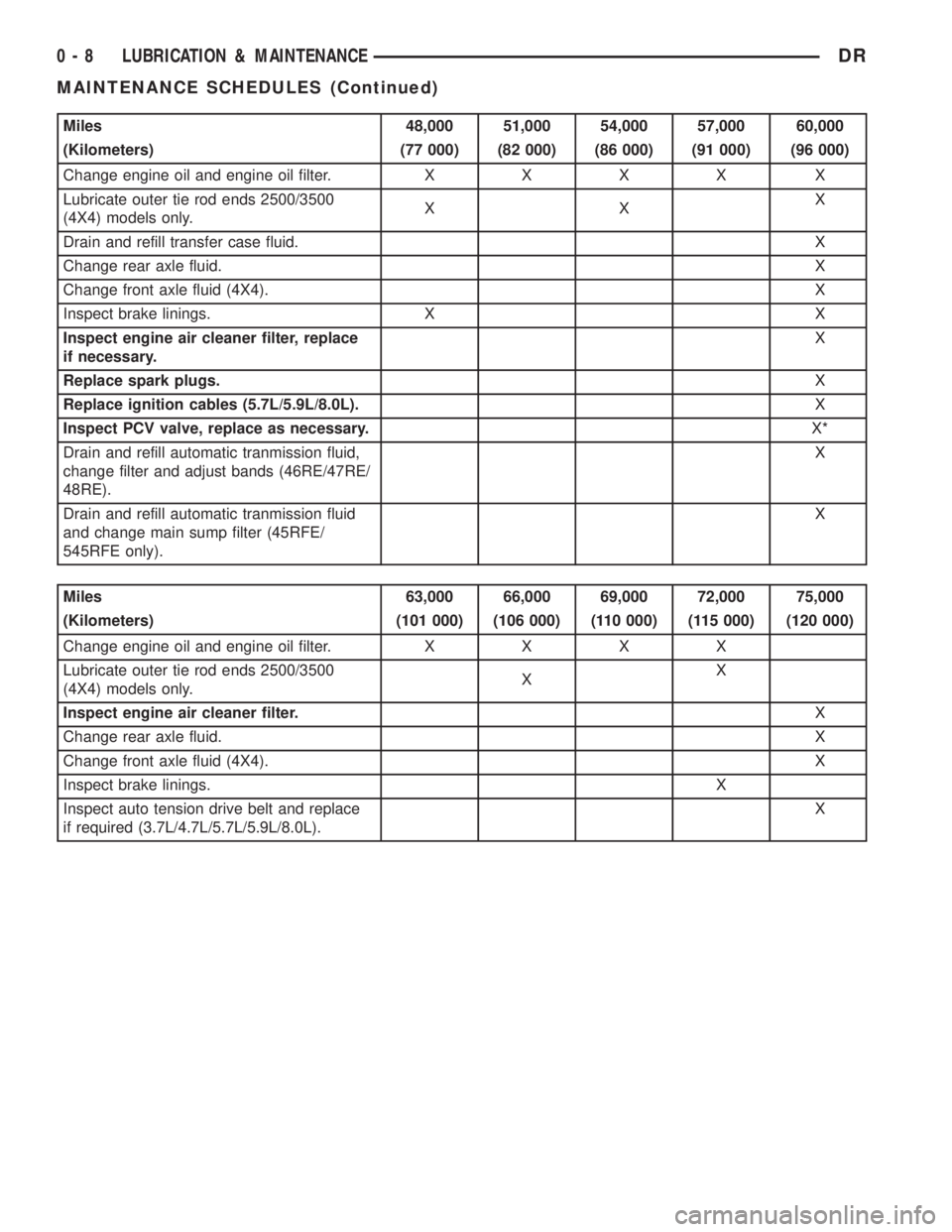
Miles 48,000 51,000 54,000 57,000 60,000
(Kilometers) (77 000) (82 000) (86 000) (91 000) (96 000)
Change engine oil and engine oil filter.XXXX X
Lubricate outer tie rod ends 2500/3500
(4X4) models only.XXX
Drain and refill transfer case fluid.X
Change rear axle fluid.X
Change front axle fluid (4X4).X
Inspect brake linings. X X
Inspect engine air cleaner filter, replace
if necessary.X
Replace spark plugs.X
Replace ignition cables (5.7L/5.9L/8.0L).X
Inspect PCV valve, replace as necessary.X*
Drain and refill automatic tranmission fluid,
change filter and adjust bands (46RE/47RE/
48RE).X
Drain and refill automatic tranmission fluid
and change main sump filter (45RFE/
545RFE only).X
Miles 63,000 66,000 69,000 72,000 75,000
(Kilometers) (101 000) (106 000) (110 000) (115 000) (120 000)
Change engine oil and engine oil filter.XXXX
Lubricate outer tie rod ends 2500/3500
(4X4) models only.XX
Inspect engine air cleaner filter.X
Change rear axle fluid.X
Change front axle fluid (4X4).X
Inspect brake linings.X
Inspect auto tension drive belt and replace
if required (3.7L/4.7L/5.7L/5.9L/8.0L).X
0 - 8 LUBRICATION & MAINTENANCEDR
MAINTENANCE SCHEDULES (Continued)
Page 22 of 2895
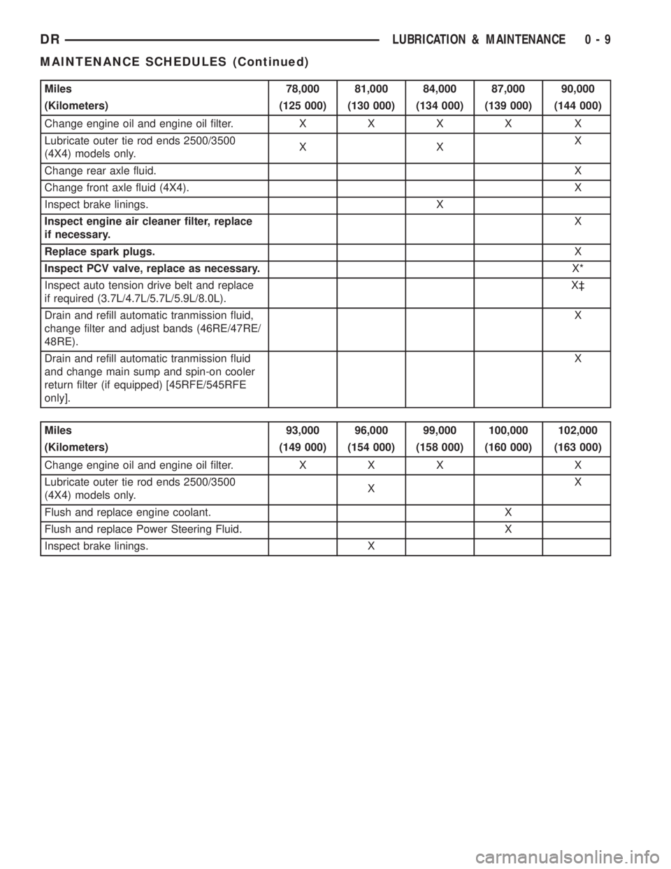
Miles 78,000 81,000 84,000 87,000 90,000
(Kilometers) (125 000) (130 000) (134 000) (139 000) (144 000)
Change engine oil and engine oil filter.XXXX X
Lubricate outer tie rod ends 2500/3500
(4X4) models only.XXX
Change rear axle fluid.X
Change front axle fluid (4X4).X
Inspect brake linings. X
Inspect engine air cleaner filter, replace
if necessary.X
Replace spark plugs.X
Inspect PCV valve, replace as necessary.X*
Inspect auto tension drive belt and replace
if required (3.7L/4.7L/5.7L/5.9L/8.0L).X³
Drain and refill automatic tranmission fluid,
change filter and adjust bands (46RE/47RE/
48RE).X
Drain and refill automatic tranmission fluid
and change main sump and spin-on cooler
return filter (if equipped) [45RFE/545RFE
only].X
Miles 93,000 96,000 99,000 100,000 102,000
(Kilometers) (149 000) (154 000) (158 000) (160 000) (163 000)
Change engine oil and engine oil filter. X X X X
Lubricate outer tie rod ends 2500/3500
(4X4) models only.XX
Flush and replace engine coolant. X
Flush and replace Power Steering Fluid. X
Inspect brake linings. X
DRLUBRICATION & MAINTENANCE 0 - 9
MAINTENANCE SCHEDULES (Continued)
Page 23 of 2895
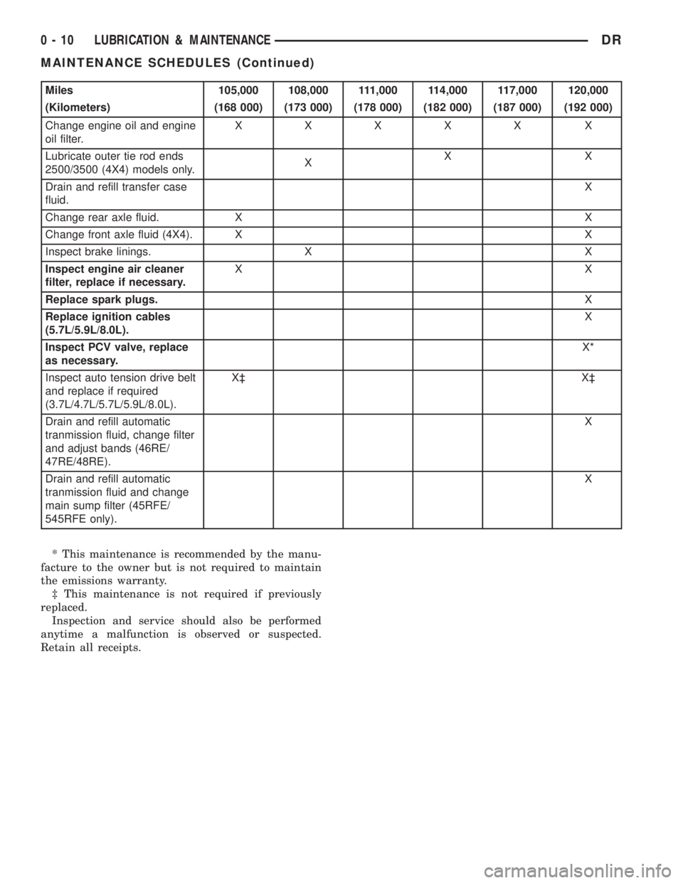
Miles 105,000 108,000 111,000 114,000 117,000 120,000
(Kilometers) (168 000) (173 000) (178 000) (182 000) (187 000) (192 000)
Change engine oil and engine
oil filter.XXXXX X
Lubricate outer tie rod ends
2500/3500 (4X4) models only.XXX
Drain and refill transfer case
fluid.X
Change rear axle fluid. X X
Change front axle fluid (4X4). X X
Inspect brake linings. X X
Inspect engine air cleaner
filter, replace if necessary.XX
Replace spark plugs.X
Replace ignition cables
(5.7L/5.9L/8.0L).X
Inspect PCV valve, replace
as necessary.X*
Inspect auto tension drive belt
and replace if required
(3.7L/4.7L/5.7L/5.9L/8.0L).X³ X³
Drain and refill automatic
tranmission fluid, change filter
and adjust bands (46RE/
47RE/48RE).X
Drain and refill automatic
tranmission fluid and change
main sump filter (45RFE/
545RFE only).X
* This maintenance is recommended by the manu-
facture to the owner but is not required to maintain
the emissions warranty.
³ This maintenance is not required if previously
replaced.
Inspection and service should also be performed
anytime a malfunction is observed or suspected.
Retain all receipts.
0 - 10 LUBRICATION & MAINTENANCEDR
MAINTENANCE SCHEDULES (Continued)
Page 24 of 2895
![DODGE RAM 2003 Service Repair Manual Schedule ªAº
Miles 6,000 12,000 18,000 24,000 30,000
(Kilometers) (10 000) (19 000) (29 000) (38 000) (48 000)
[Months] [6] [12] [18] [24] [30]
Change engine oil and engine oil filter.XXXX X
Check t](/img/12/56913/w960_56913-23.png "DODGE RAM 2003 Service Repair Manual Schedule ªAº
Miles 6,000 12,000 18,000 24,000 30,000
(Kilometers) (10 000) (19 000) (29 000) (38 000) (48 000)
[Months] [6] [12] [18] [24] [30]
Change engine oil and engine oil filter.XXXX X
Check t")
Schedule ªAº
Miles 6,000 12,000 18,000 24,000 30,000
(Kilometers) (10 000) (19 000) (29 000) (38 000) (48 000)
[Months] [6] [12] [18] [24] [30]
Change engine oil and engine oil filter.XXXX X
Check transfer case fluid level.X
Lubricate outer tie rod ends 2500/3500
(4X4) models only.XXXX X
Inspect brake linings. X
Replace engine air cleaner filter.X
Replace spark plugs.X
Miles 36,000 42,000 48,000 54,000 60,000 66,000
(Kilometers) (58 000) (67 000) (77 000) (84 000) (96 000) (106 000)
[Months] [36] [42] [48] [54] [60] [66]
Change engine oil and engine
oil filter.XXXXX
X
Check transfer case fluid
level.X
Lubricate outer tie rod ends
2500/3500 (4X4) models only.XXXXX X
Flush and replace engine
coolant at 60 months,
regardless of mileage.X
Inspect brake linings. X X
Replace engine air cleaner
filter.X
Replace spark plugs.X
Inspect PCV valve, replace
as necessary.X*
Replace ignition cables
(5.7L/5.9L/8.0L).X
DRLUBRICATION & MAINTENANCE 0 - 11
MAINTENANCE SCHEDULES (Continued)
Page 25 of 2895
![DODGE RAM 2003 Service Repair Manual Miles 72,000 78,000 84,000 90,000 96,000 100,000
(Kilometers) (115 000) (125 000) (134 000) (144 000) (154 000) (160 000)
[Months] [72] [78] [84] [90] [96]
Change engine oil and engine oil filter.XXXX](/img/12/56913/w960_56913-24.png "DODGE RAM 2003 Service Repair Manual Miles 72,000 78,000 84,000 90,000 96,000 100,000
(Kilometers) (115 000) (125 000) (134 000) (144 000) (154 000) (160 000)
[Months] [72] [78] [84] [90] [96]
Change engine oil and engine oil filter.XXXX")
Miles 72,000 78,000 84,000 90,000 96,000 100,000
(Kilometers) (115 000) (125 000) (134 000) (144 000) (154 000) (160 000)
[Months] [72] [78] [84] [90] [96]
Change engine oil and engine oil filter.XXXXX
Lubricate outer tie rod ends 2500/3500
(4X4) models only.XXXXX
Drain and refill transfer case fluid. X
Flush and replace engine coolant, if not
done at 60 mos.X
Flush and replace Power Steering Fluid.X
Inspect brake linings. X X
Replace engine air cleaner filter.X
Replace spark plugs.X
Replace ignition cables (5.7L/5.9L/
8.0L).X
Inspect PCV valve, replace as
necessary.X*
Inspect auto tension drive belt and
replace if required (3.7L/4.7L/5.7L/5.9L/
8.0L).X
Drain and refill automatic tranmission
fluid, change filter and adjust bands
(46RE/47RE/48RE).X
Drain and refill automatic tranmission
fluid and change main sump filter and
spin-on cooler return filter (if equipped)
[45RFE/545RFE only].X
Miles 102,000 108,000 114,000 120,000
(Kilometers) (163 000) (173 000) (182 000) (192 000)
[Months] [102] [108] [114] [120]
Change engine oil and engine oil filter. X X X X
Check transfer case fluid level.X
Lubricate outer tie rod ends 2500/3500 (4X4) models only. X X X X
Inspect brake linings. X
Inspect auto tension drive belt and replace if required
(3.7L/4.7L/5.7L/5.9L/8.0L).X³X³
Replace engine air cleaner filter.X
Replace spark plugs.X
* This maintenance is recommended by the manu-
facture to the owner but is not required to maintain
the emissions warranty.
³ This maintenance is not required if previously
replaced.
Inspection and service should also be performed
anytime a malfunction is observed or suspected.
Retain all receipts.WARNING: You can be badly injured working on or
around a motor vehicle. Do only that service work
for which you have the knowledge and the right
equipment. If you have any doubt about your ability
to perform a service job, take your vehicle to a
competent mechanic.
0 - 12 LUBRICATION & MAINTENANCEDR
MAINTENANCE SCHEDULES (Continued)
Page 1261 of 2895
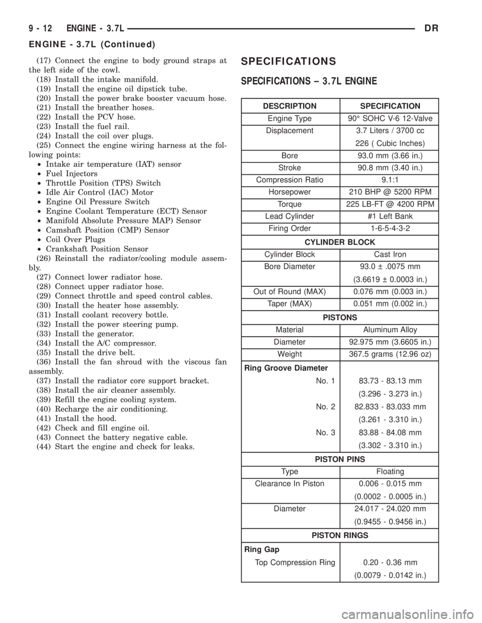
(17) Connect the engine to body ground straps at
the left side of the cowl.
(18) Install the intake manifold.
(19) Install the engine oil dipstick tube.
(20) Install the power brake booster vacuum hose.
(21) Install the breather hoses.
(22) Install the PCV hose.
(23) Install the fuel rail.
(24) Install the coil over plugs.
(25) Connect the engine wiring harness at the fol-
lowing points:
²Intake air temperature (IAT) sensor
²Fuel Injectors
²Throttle Position (TPS) Switch
²Idle Air Control (IAC) Motor
²Engine Oil Pressure Switch
²Engine Coolant Temperature (ECT) Sensor
²Manifold Absolute Pressure MAP) Sensor
²Camshaft Position (CMP) Sensor
²Coil Over Plugs
²Crankshaft Position Sensor
(26) Reinstall the radiator/cooling module assem-
bly.
(27) Connect lower radiator hose.
(28) Connect upper radiator hose.
(29) Connect throttle and speed control cables.
(30) Install the heater hose assembly.
(31) Install coolant recovery bottle.
(32) Install the power steering pump.
(33) Install the generator.
(34) Install the A/C compressor.
(35) Install the drive belt.
(36) Install the fan shroud with the viscous fan
assembly.
(37) Install the radiator core support bracket.
(38) Install the air cleaner assembly.
(39) Refill the engine cooling system.
(40) Recharge the air conditioning.
(41) Install the hood.
(42) Check and fill engine oil.
(43) Connect the battery negative cable.
(44) Start the engine and check for leaks.SPECIFICATIONS
SPECIFICATIONS ± 3.7L ENGINE
DESCRIPTION SPECIFICATION
Engine Type 90É SOHC V-6 12-Valve
Displacement 3.7 Liters / 3700 cc
226 ( Cubic Inches)
Bore 93.0 mm (3.66 in.)
Stroke 90.8 mm (3.40 in.)
Compression Ratio 9.1:1
Horsepower 210 BHP @ 5200 RPM
Torque 225 LB-FT @ 4200 RPM
Lead Cylinder #1 Left Bank
Firing Order 1-6-5-4-3-2
CYLINDER BLOCK
Cylinder Block Cast Iron
Bore Diameter 93.0 .0075 mm
(3.6619 0.0003 in.)
Out of Round (MAX) 0.076 mm (0.003 in.)
Taper (MAX) 0.051 mm (0.002 in.)
PISTONS
Material Aluminum Alloy
Diameter 92.975 mm (3.6605 in.)
Weight 367.5 grams (12.96 oz)
Ring Groove Diameter
No. 1 83.73 - 83.13 mm
(3.296 - 3.273 in.)
No. 2 82.833 - 83.033 mm
(3.261 - 3.310 in.)
No. 3 83.88 - 84.08 mm
(3.302 - 3.310 in.)
PISTON PINS
Type Floating
Clearance In Piston 0.006 - 0.015 mm
(0.0002 - 0.0005 in.)
Diameter 24.017 - 24.020 mm
(0.9455 - 0.9456 in.)
PISTON RINGS
Ring Gap
Top Compression Ring 0.20 - 0.36 mm
(0.0079 - 0.0142 in.)
9 - 12 ENGINE - 3.7LDR
ENGINE - 3.7L (Continued)
Page 1285 of 2895
(12) Remove cylinder head cover retaining bolts.
(13) Remove cylinder head cover.
INSTALLATION
CAUTION: Do not use harsh cleaners to clean the
cylinder head covers. Severe damage to covers
may occur.
NOTE: The gasket may be used again, provided no
cuts, tears, or deformation has occurred.
(1) Clean cylinder head cover and both sealing sur-
faces. Inspect and replace gasket as necessary.
(2) Tighten cylinder head cover bolts and double
ended studs to 12 N´m (105 in. lbs).
(3) Install right rear breather tube and filter
assembly.
(4) Connect injector, ignition coil electrical connec-
tors and harness retaining clips.
(5) Install the oil fill tube.
(6) Install PCV hose.
(7) Install heater hoses.
(8) Install air conditioning compressor retaining
bolts.
(9) Install accessory drive belt(Refer to 7 - COOL-
ING/ACCESSORY DRIVE/DRIVE BELTS - INSTAL-
LATION).
(10) Fill Cooling system(Refer to 7 - COOLING -
STANDARD PROCEDURE).
(11) Install air cleaner assembly, resonator assem-
bly and air inlet hose.
(12) Connect battery negative cable.
ROCKER ARM
DESCRIPTION
The rocker arms are steel stampings with an inte-
gral roller bearing. The rocker arms incorporate a 2.8
mm (0.11 inch) oil hole in the lash adjuster socket for
roller and camshaft lubrication.
REMOVAL
NOTE: Disconnect the battery negative cable to pre-
vent accidental starter engagement.
(1) Remove the cylinder head cover (Refer to 9 -
ENGINE/CYLINDER HEAD/CYLINDER HEAD
COVER(S) - REMOVAL).
(2) For rocker arm removal on cylinder #4, Rotate
the crankshaft until cylinder #1 is at BDC intake
stroke.(3) For rocker arm removal on cylinder #1, Rotate
the crankshaft until cylinder #1 is at BDC combus-
tion stroke.
(4) For rocker arm removal on cylinders #3 and #5,
Rotate the crankshaft until cylinder #1 is at TDC
exhaust stroke.
(5) For rocker arm removal on cylinders #2 and #6,
Rotate the crankshaft until cylinder #1 is at TDC
ignition stroke.
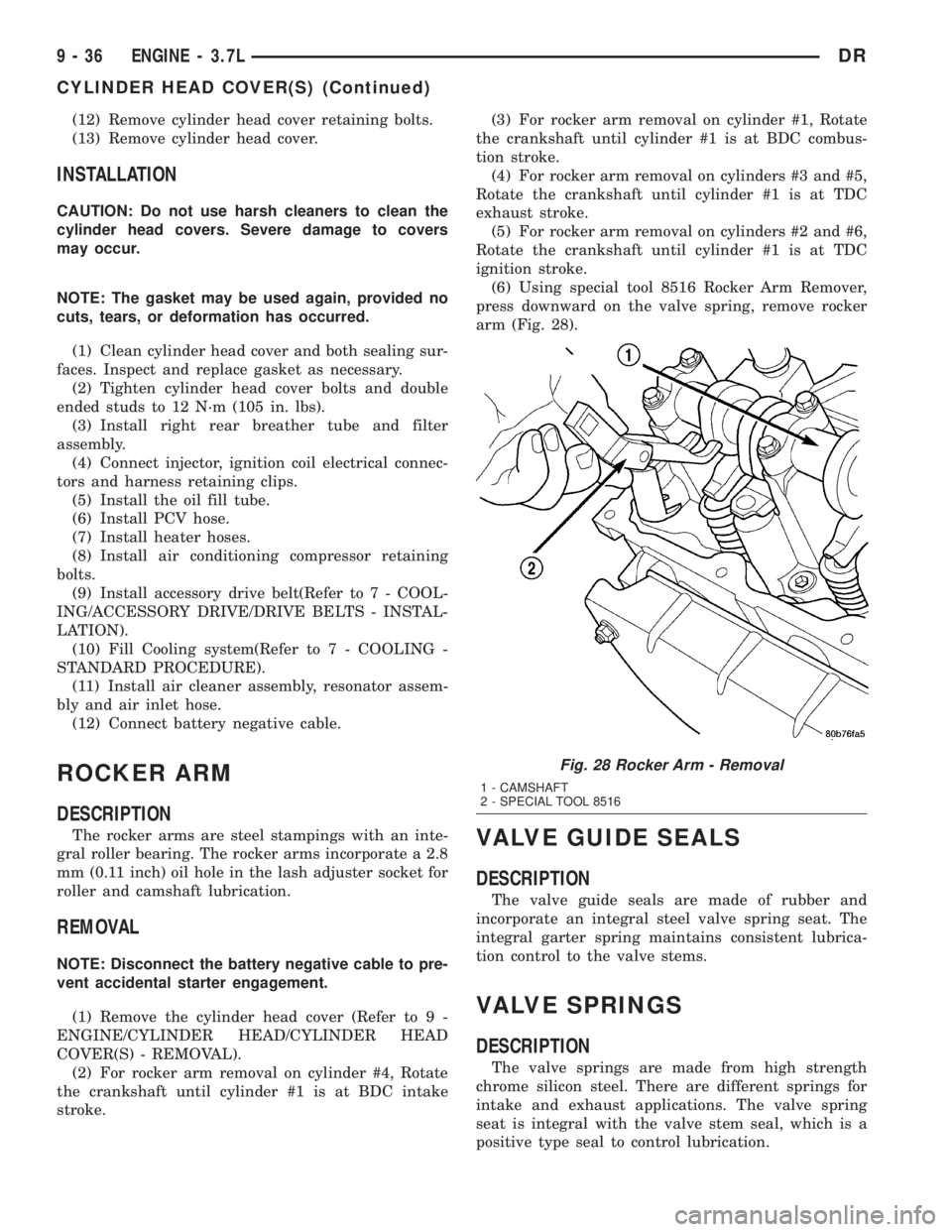
(6) Using special tool 8516 Rocker Arm Remover,
press downward on the valve spring, remove rocker
arm (Fig. 28).
VALVE GUIDE SEALS
DESCRIPTION
The valve guide seals are made of rubber and
incorporate an integral steel valve spring seat. The
integral garter spring maintains consistent lubrica-
tion control to the valve stems.
VALVE SPRINGS
DESCRIPTION
The valve springs are made from high strength
chrome silicon steel. There are different springs for
intake and exhaust applications. The valve spring
seat is integral with the valve stem seal, which is a
positive type seal to control lubrication.
Fig. 28 Rocker Arm - Removal
1 - CAMSHAFT
2 - SPECIAL TOOL 8516
9 - 36 ENGINE - 3.7LDR
CYLINDER HEAD COVER(S) (Continued)
Page 1312 of 2895
DIAGNOSIS AND TESTING
DIAGNOSIS AND TESTINGÐENGINE OIL LEAK
Begin with a thorough visual inspection of the
engine, particularly at the area of the suspected leak.
If an oil leak source is not readily identifiable, the
following steps should be followed:
(1) Do not clean or degrease the engine at this
time because some solvents may cause rubber to
swell, temporarily stopping the leak.
(2) Add an oil soluble dye (use as recommended by
manufacturer). Start the engine and let idle for
approximately 15 minutes. Check the oil dipstick to
make sure the dye is thoroughly mixed as indicated
with a bright yellow color under a black light.
(3) Using a black light, inspect the entire engine
for fluorescent dye, particularly at the suspected area
of oil leak. If the oil leak is found and identified,
repair per service manual instructions.
(4) If dye is not observed, drive the vehicle at var-
ious speeds for approximately 24 km (15 miles), and
repeat inspection.If the oil leak source is not pos-
itively identified at this time, proceed with the air
leak detection test method.
Air Leak Detection Test Method
(1) Disconnect the breather cap to air cleaner hose
at the breather cap end. Cap or plug breather cap
nipple.
(2) Remove the PCV valve from the cylinder head
cover. Cap or plug the PCV valve grommet.
(3) Attach an air hose with pressure gauge and
regulator to the dipstick tube.
CAUTION: Do not subject the engine assembly to
more than 20.6 kPa (3 PSI) of test pressure.
(4) Gradually apply air pressure from 1 psi to 2.5
psi maximum while applying soapy water at the sus-
pected source. Adjust the regulator to the suitable
test pressure that provide the best bubbles which
will pinpoint the leak source. If the oil leak is
detected and identified, repair per service manual
procedures.
(5) If the leakage occurs at the rear oil seal area,
refer to the section, Inspection for Rear Seal Area
Leak.
(6) If no leaks are detected, turn off the air supply
and remove the air hose and all plugs and caps.
Install the PCV valve and breather cap hose.(7) Clean the oil off the suspect oil leak area using
a suitable solvent. Drive the vehicle at various
speeds approximately 24 km (15 miles). Inspect the
engine for signs of an oil leak by using a black light.
INSPECTION FOR REAR SEAL AREA LEAKS
Since it is sometimes difficult to determine the
source of an oil leak in the rear seal area of the
engine, a more involved inspection is necessary. The
following steps should be followed to help pinpoint
the source of the leak.
If the leakage occurs at the crankshaft rear oil seal
area:
(1) Disconnect the battery.
(2) Raise the vehicle.
(3) Remove torque converter or clutch housing
cover and inspect rear of block for evidence of oil.
Use a black light to check for the oil leak:
(a) Circular spray pattern generally indicates
seal leakage or crankshaft damage.
(b) Where leakage tends to run straight down,
possible causes are a porous block, distributor seal,
camshaft bore cup plugs oil galley pipe plugs, oil
filter runoff, and main bearing cap to cylinder
block mating surfaces.
(4) If no leaks are detected, pressurize the crank-
case as outlined in the, Inspection (Engine oil Leaks
in general)
CAUTION: Do not exceed 20.6 kPa (3 psi).
(5) If the leak is not detected, very slowly turn the
crankshaft and watch for leakage. If a leak is
detected between the crankshaft and seal while
slowly turning the crankshaft, it is possible the
crankshaft seal surface is damaged. The seal area on
the crankshaft could have minor nicks or scratches
that can be polished out with emery cloth.
CAUTION: Use extreme caution when crankshaft
polishing is necessary to remove minor nicks and
scratches. The crankshaft seal flange is especially
machined to complement the function of the rear oil
seal.
(6) For bubbles that remain steady with shaft
rotation, no further inspection can be done until dis-
assembled.
DRENGINE - 3.7L 9 - 63
LUBRICATION (Continued)
Page 1399 of 2895
DIAGNOSIS AND TESTING
DIAGNOSIS AND TESTING - CHECKING
ENGINE OIL PRESSURE
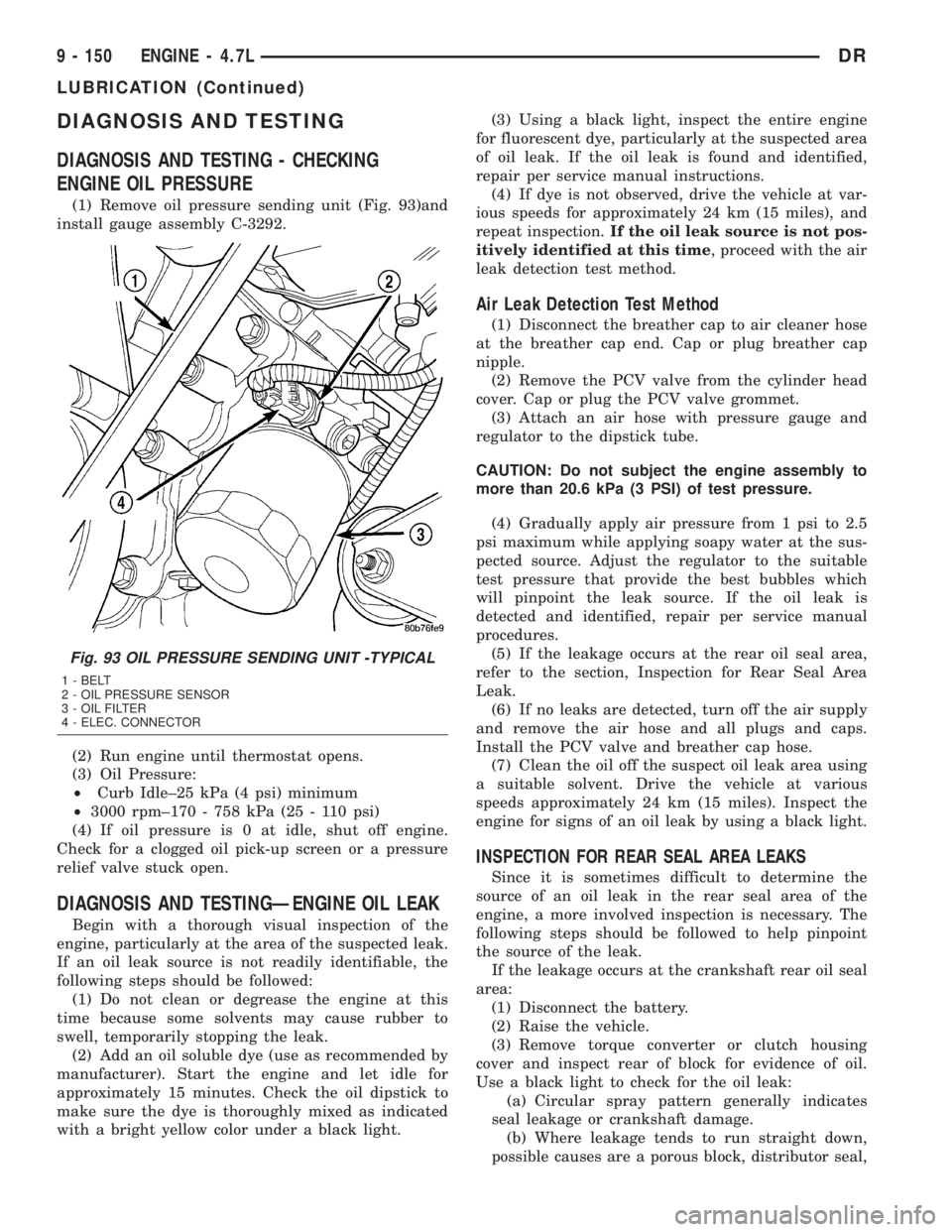
(1) Remove oil pressure sending unit (Fig. 93)and
install gauge assembly C-3292.
(2) Run engine until thermostat opens.
(3) Oil Pressure:
²Curb Idle±25 kPa (4 psi) minimum
²3000 rpm±170 - 758 kPa (25 - 110 psi)
(4) If oil pressure is 0 at idle, shut off engine.
Check for a clogged oil pick-up screen or a pressure
relief valve stuck open.
DIAGNOSIS AND TESTINGÐENGINE OIL LEAK
Begin with a thorough visual inspection of the
engine, particularly at the area of the suspected leak.
If an oil leak source is not readily identifiable, the
following steps should be followed:
(1) Do not clean or degrease the engine at this
time because some solvents may cause rubber to
swell, temporarily stopping the leak.
(2) Add an oil soluble dye (use as recommended by
manufacturer). Start the engine and let idle for
approximately 15 minutes. Check the oil dipstick to
make sure the dye is thoroughly mixed as indicated
with a bright yellow color under a black light.(3) Using a black light, inspect the entire engine
for fluorescent dye, particularly at the suspected area
of oil leak. If the oil leak is found and identified,
repair per service manual instructions.
(4) If dye is not observed, drive the vehicle at var-
ious speeds for approximately 24 km (15 miles), and
repeat inspection.If the oil leak source is not pos-
itively identified at this time, proceed with the air
leak detection test method.
Air Leak Detection Test Method
(1) Disconnect the breather cap to air cleaner hose
at the breather cap end. Cap or plug breather cap
nipple.
(2) Remove the PCV valve from the cylinder head
cover. Cap or plug the PCV valve grommet.
(3) Attach an air hose with pressure gauge and
regulator to the dipstick tube.
CAUTION: Do not subject the engine assembly to
more than 20.6 kPa (3 PSI) of test pressure.
(4) Gradually apply air pressure from 1 psi to 2.5
psi maximum while applying soapy water at the sus-
pected source. Adjust the regulator to the suitable
test pressure that provide the best bubbles which
will pinpoint the leak source. If the oil leak is
detected and identified, repair per service manual
procedures.
(5) If the leakage occurs at the rear oil seal area,
refer to the section, Inspection for Rear Seal Area
Leak.
(6) If no leaks are detected, turn off the air supply
and remove the air hose and all plugs and caps.
Install the PCV valve and breather cap hose.
(7) Clean the oil off the suspect oil leak area using
a suitable solvent. Drive the vehicle at various
speeds approximately 24 km (15 miles). Inspect the
engine for signs of an oil leak by using a black light.
INSPECTION FOR REAR SEAL AREA LEAKS
Since it is sometimes difficult to determine the
source of an oil leak in the rear seal area of the
engine, a more involved inspection is necessary. The
following steps should be followed to help pinpoint
the source of the leak.
If the leakage occurs at the crankshaft rear oil seal
area:
(1) Disconnect the battery.
(2) Raise the vehicle.
(3) Remove torque converter or clutch housing
cover and inspect rear of block for evidence of oil.
Use a black light to check for the oil leak:
(a) Circular spray pattern generally indicates
seal leakage or crankshaft damage.
(b) Where leakage tends to run straight down,
possible causes are a porous block, distributor seal,
Fig. 93 OIL PRESSURE SENDING UNIT -TYPICAL
1 - BELT
2 - OIL PRESSURE SENSOR
3 - OIL FILTER
4 - ELEC. CONNECTOR
9 - 150 ENGINE - 4.7LDR
LUBRICATION (Continued)