Power DODGE RAM 2003 Service Repair Manual
[x] Cancel search | Manufacturer: DODGE, Model Year: 2003, Model line: RAM, Model: DODGE RAM 2003Pages: 2895, PDF Size: 83.15 MB
Page 1 of 2895
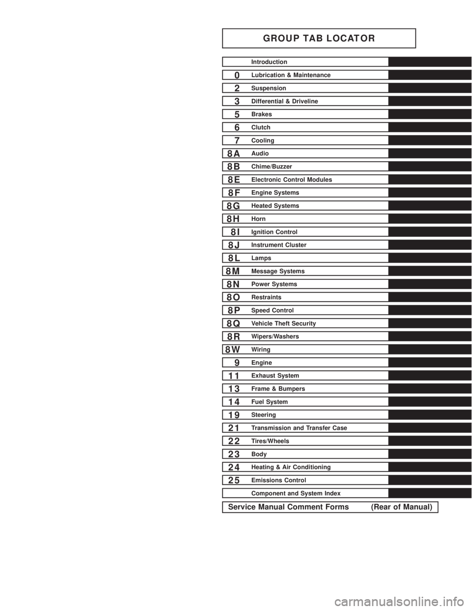
GROUP TAB LOCATOR
Introduction
0Lubrication & Maintenance
2Suspension
3Differential & Driveline
5Brakes
6Clutch
7Cooling
8AAudio
8BChime/Buzzer
8EElectronic Control Modules
8FEngine Systems
8GHeated Systems
8HHorn
8IIgnition Control
8JInstrument Cluster
8LLamps
8MMessage Systems
8NPower Systems
8ORestraints
8PSpeed Control
8QVehicle Theft Security
8RWipers/Washers
8WWiring
9Engine
11Exhaust System
13Frame & Bumpers
14Fuel System
19Steering
21Transmission and Transfer Case
22Tires/Wheels
23Body
24Heating & Air Conditioning
25Emissions Control
Component and System Index
Service Manual Comment Forms (Rear of Manual)
Page 14 of 2895
LUBRICATION & MAINTENANCE
TABLE OF CONTENTS
page page
INTERNATIONAL SYMBOLS
DESCRIPTION..........................1
FLUID TYPES
DESCRIPTION
DESCRIPTION - FUEL REQUIREMENTS -
DIESEL ENGINE.......................1
DESCRIPTION - ENGINE OIL AND
LUBRICANTS.........................2
DESCRIPTION - POWER STEERING FLUID . . 3
DESCRIPTION - ENGINE COOLANT........3
DESCRIPTION - TRANSFER CASE - NV241
GENII...............................4
DESCRIPTION - TRANSFER CASE - NV271 . . 4
DESCRIPTION - TRANSFER CASE - NV243 . . 4
DESCRIPTION - TRANSFER CASE - NV273 . . 4
DESCRIPTION - AXLE...................4DESCRIPTION - MANUAL TRANSMISSION . . . 4
DESCRIPTION - AUTOMATIC
TRANSMISSION FLUID..................4
OPERATION - AUTOMATIC TRANSMISSION
FLUID...............................5
FLUID CAPACITIES
SPECIFICATIONS
FLUID CAPACITIES.....................5
MAINTENANCE SCHEDULES
DESCRIPTION..........................6
JUMP STARTING
STANDARD PROCEDURE - JUMP STARTING...13
HOISTING
STANDARD PROCEDURE - HOISTING.......14
TOWING
STANDARD PROCEDURE - TOWING........15
INTERNATIONAL SYMBOLS
DESCRIPTION
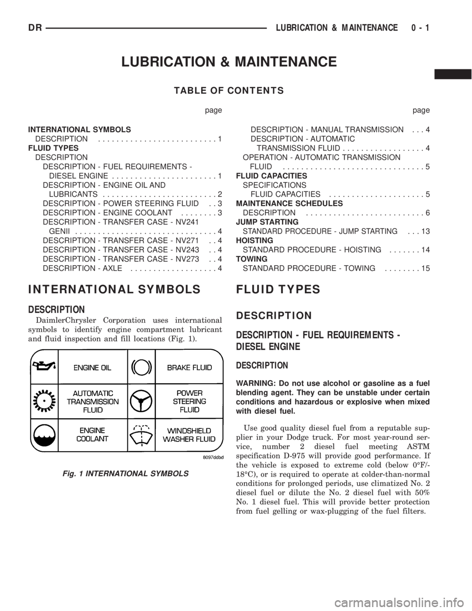
DaimlerChrysler Corporation uses international
symbols to identify engine compartment lubricant
and fluid inspection and fill locations (Fig. 1).
FLUID TYPES
DESCRIPTION
DESCRIPTION - FUEL REQUIREMENTS -
DIESEL ENGINE
DESCRIPTION
WARNING: Do not use alcohol or gasoline as a fuel
blending agent. They can be unstable under certain
conditions and hazardous or explosive when mixed
with diesel fuel.
Use good quality diesel fuel from a reputable sup-
plier in your Dodge truck. For most year-round ser-
vice, number 2 diesel fuel meeting ASTM
specification D-975 will provide good performance. If
the vehicle is exposed to extreme cold (below 0ÉF/-
18ÉC), or is required to operate at colder-than-normal
conditions for prolonged periods, use climatized No. 2
diesel fuel or dilute the No. 2 diesel fuel with 50%
No. 1 diesel fuel. This will provide better protection
from fuel gelling or wax-plugging of the fuel filters.
Fig. 1 INTERNATIONAL SYMBOLS
DRLUBRICATION & MAINTENANCE 0 - 1
Page 16 of 2895
SPECIALIZED LUBRICANTS AND OILS
Some maintenance or repair procedures may
require the use of specialized lubricants or oils. Con-
sult the appropriate sections in this manual for the
correct application of these lubricants.
DESCRIPTION - POWER STEERING FLUID
MopartATF +4, Automatic Transmission Fluid is
required in the power steering system. Substitute
fluids can induce power steering system failure.
MopartATF +4, Automatic Transmission Fluid
when new is red in color. The ATF is dyed red so it
can be identified from other fluids used in the vehicle
such as engine oil or antifreeze. The red color is not
permanent and is not an indicator of fluid condition.
As the vehicle is driven, the ATF will begin to look
darker in color and may eventually become brown.
This is normal.ATF+4 also has a unique odor that
may change with age. Consequently, odor and color
cannot be used to indicate the fluid condition or the
need for a fluid change.
DESCRIPTION - ENGINE COOLANT
WARNING: ANTIFREEZE IS AN ETHYLENE GLYCOL
BASE COOLANT AND IS HARMFUL IF SWAL-
LOWED OR INHALED. IF SWALLOWED, DRINK
TWO GLASSES OF WATER AND INDUCE VOMIT-
ING. IF INHALED, MOVE TO FRESH AIR AREA.
SEEK MEDICAL ATTENTION IMMEDIATELY. DO NOT
STORE IN OPEN OR UNMARKED CONTAINERS.
WASH SKIN AND CLOTHING THOROUGHLY AFTER
COMING IN CONTACT WITH ETHYLENE GLYCOL.
KEEP OUT OF REACH OF CHILDREN. DISPOSE OF
GLYCOL BASE COOLANT PROPERLY, CONTACT
YOUR DEALER OR GOVERNMENT AGENCY FOR
LOCATION OF COLLECTION CENTER IN YOUR
AREA. DO NOT OPEN A COOLING SYSTEM WHEN
THE ENGINE IS AT OPERATING TEMPERATURE OR
HOT UNDER PRESSURE, PERSONAL INJURY CAN
RESULT. AVOID RADIATOR COOLING FAN WHENENGINE COMPARTMENT RELATED SERVICE IS
PERFORMED, PERSONAL INJURY CAN RESULT.
CAUTION: Use of Propylene Glycol based coolants
is not recommended, as they provide less freeze
protection and less corrosion protection.
The cooling system is designed around the coolant.
The coolant must accept heat from engine metal, in
the cylinder head area near the exhaust valves and
engine block. Then coolant carries the heat to the
radiator where the tube/fin radiator can transfer the
heat to the air.
The use of aluminum cylinder blocks, cylinder
heads, and water pumps requires special corrosion
protection. MopartAntifreeze/Coolant, 5
Year/100,000 Mile Formula (MS-9769), or the equiva-
lent ethylene glycol base coolant with organic corro-
sion inhibitors (called HOAT, for Hybrid Organic
Additive Technology) is recommended. This coolant
offers the best engine cooling without corrosion when
mixed with 50% Ethylene Glycol and 50% distilled
water to obtain a freeze point of -37ÉC (-35ÉF). If it
loses color or becomes contaminated, drain, flush,
and replace with fresh properly mixed coolant solu-
tion.
CAUTION: MoparTAntifreeze/Coolant, 5
Year/100,000 Mile Formula (MS-9769) may not be
mixed with any other type of antifreeze. Mixing of
coolants other than specified (non-HOAT or other
HOAT), may result in engine damage that may not
be covered under the new vehicle warranty, and
decreased corrosion protection.
COOLANT PERFORMANCE
The required ethylene-glycol (antifreeze) and water
mixture depends upon climate and vehicle operating
conditions. The coolant performance of various mix-
tures follows:
Pure Water-Water can absorb more heat than a
mixture of water and ethylene-glycol. This is for pur-
pose of heat transfer only. Water also freezes at a
higher temperature and allows corrosion.
100 percent Ethylene-Glycol-The corrosion
inhibiting additives in ethylene-glycol need the pres-
ence of water to dissolve. Without water, additives
form deposits in system. These act as insulation
causing temperature to rise to as high as 149ÉC
(300ÉF). This temperature is hot enough to melt plas-
tic and soften solder. The increased temperature can
result in engine detonation. In addition, 100 percent
ethylene-glycol freezes at -22ÉC (-8ÉF).
50/50 Ethylene-Glycol and Water-Is the recom-
mended mixture, it provides protection against freez-
ing to -37ÉC (-34ÉF). The antifreeze concentration
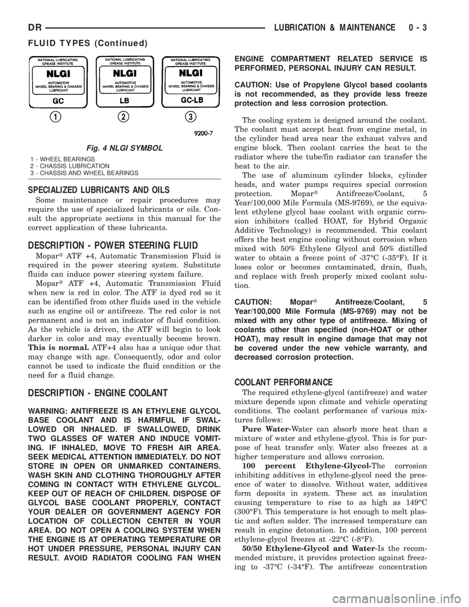
Fig. 4 NLGI SYMBOL
1 - WHEEL BEARINGS
2 - CHASSIS LUBRICATION
3 - CHASSIS AND WHEEL BEARINGS
DRLUBRICATION & MAINTENANCE 0 - 3
FLUID TYPES (Continued)
Page 18 of 2895
FLUID ADDITIVES
DaimlerChrysler strongly recommends against the
addition of any fluids to the transmission, other than
those automatic transmission fluids listed above.
Exceptions to this policy are the use of special dyes
to aid in detecting fluid leaks.
Various ªspecialº additives and supplements exist
that claim to improve shift feel and/or quality. These
additives and others also claim to improve converter
clutch operation and inhibit overheating, oxidation,
varnish, and sludge. These claims have not been sup-
ported to the satisfaction of DaimlerChrysler and
these additivesmust not be used.The use of trans-
mission ªsealersº should also be avoided, since they
may adversely affect the integrity of transmission
seals.
OPERATION - AUTOMATIC TRANSMISSION
FLUID
The automatic transmission fluid is selected based
upon several qualities. The fluid must provide a high
level of protection for the internal components by
providing a lubricating film between adjacent metal
components. The fluid must also be thermally stable
so that it can maintain a consistent viscosity through
a large temperature range. If the viscosity stays con-
stant through the temperature range of operation,
transmission operation and shift feel will remain con-
sistent. Transmission fluid must also be a good con-
ductor of heat. The fluid must absorb heat from the
internal transmission components and transfer that
heat to the transmission case.
FLUID CAPACITIES
SPECIFICATIONS
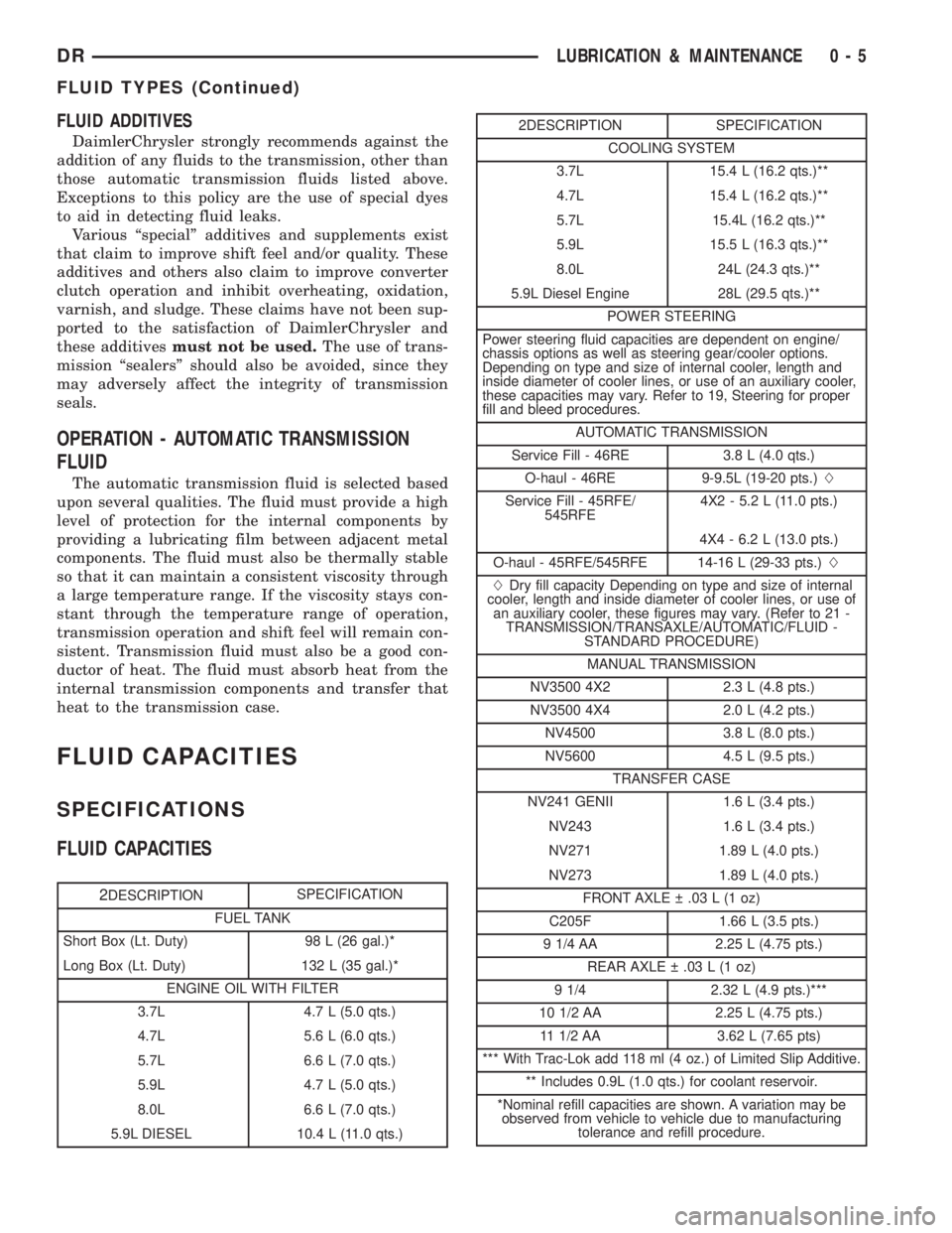
FLUID CAPACITIES
2DESCRIPTIONSPECIFICATION
FUEL TANK
Short Box (Lt. Duty) 98 L (26 gal.)*
Long Box (Lt. Duty) 132 L (35 gal.)*
ENGINE OIL WITH FILTER
3.7L 4.7 L (5.0 qts.)
4.7L 5.6 L (6.0 qts.)
5.7L 6.6 L (7.0 qts.)
5.9L 4.7 L (5.0 qts.)
8.0L 6.6 L (7.0 qts.)
5.9L DIESEL 10.4 L (11.0 qts.)
2DESCRIPTION SPECIFICATION
COOLING SYSTEM
3.7L 15.4 L (16.2 qts.)**
4.7L 15.4 L (16.2 qts.)**
5.7L 15.4L (16.2 qts.)**
5.9L 15.5 L (16.3 qts.)**
8.0L 24L (24.3 qts.)**
5.9L Diesel Engine 28L (29.5 qts.)**
POWER STEERING
Power steering fluid capacities are dependent on engine/
chassis options as well as steering gear/cooler options.
Depending on type and size of internal cooler, length and
inside diameter of cooler lines, or use of an auxiliary cooler,
these capacities may vary. Refer to 19, Steering for proper
fill and bleed procedures.
AUTOMATIC TRANSMISSION
Service Fill - 46RE 3.8 L (4.0 qts.)
O-haul - 46RE 9-9.5L (19-20 pts.)L
Service Fill - 45RFE/
545RFE4X2 - 5.2 L (11.0 pts.)
4X4 - 6.2 L (13.0 pts.)
O-haul - 45RFE/545RFE 14-16 L (29-33 pts.)L
LDry fill capacity Depending on type and size of internal
cooler, length and inside diameter of cooler lines, or use of
an auxiliary cooler, these figures may vary. (Refer to 21 -
TRANSMISSION/TRANSAXLE/AUTOMATIC/FLUID -
STANDARD PROCEDURE)
MANUAL TRANSMISSION
NV3500 4X2 2.3 L (4.8 pts.)
NV3500 4X4 2.0 L (4.2 pts.)
NV4500 3.8 L (8.0 pts.)
NV5600 4.5 L (9.5 pts.)
TRANSFER CASE
NV241 GENII 1.6 L (3.4 pts.)
NV243 1.6 L (3.4 pts.)
NV271 1.89 L (4.0 pts.)
NV273 1.89 L (4.0 pts.)
FRONT AXLE .03 L (1 oz)
C205F 1.66 L (3.5 pts.)
9 1/4 AA 2.25 L (4.75 pts.)
REAR AXLE .03 L (1 oz)
9 1/4 2.32 L (4.9 pts.)***
10 1/2 AA 2.25 L (4.75 pts.)
11 1/2 AA 3.62 L (7.65 pts)
*** With Trac-Lok add 118 ml (4 oz.) of Limited Slip Additive.
** Includes 0.9L (1.0 qts.) for coolant reservoir.
*Nominal refill capacities are shown. A variation may be
observed from vehicle to vehicle due to manufacturing
tolerance and refill procedure.
DRLUBRICATION & MAINTENANCE 0 - 5
FLUID TYPES (Continued)
Page 19 of 2895
MAINTENANCE SCHEDULES
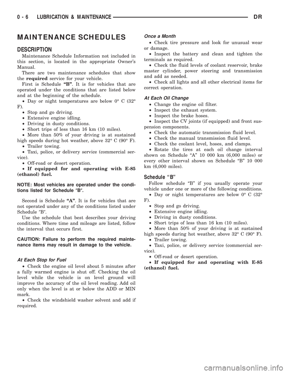
DESCRIPTION
Maintenance Schedule Information not included in
this section, is located in the appropriate Owner's
Manual.
There are two maintenance schedules that show
therequiredservice for your vehicle.
First is ScheduleªBº. It is for vehicles that are
operated under the conditions that are listed below
and at the beginning of the schedule.
²Day or night temperatures are below 0É C (32É
F).
²Stop and go driving.
²Extensive engine idling.
²Driving in dusty conditions.
²Short trips of less than 16 km (10 miles).
²More than 50% of your driving is at sustained
high speeds during hot weather, above 32É C (90É F).
²Trailer towing.
²Taxi, police, or delivery service (commercial ser-
vice).
²Off-road or desert operation.
²If equipped for and operating with E-85
(ethanol) fuel.
NOTE: Most vehicles are operated under the condi-
tions listed for Schedule(B(.
Second is ScheduleªAº. It is for vehicles that are
not operated under any of the conditions listed under
Schedule9B9.
Use the schedule that best describes your driving
conditions. Where time and mileage are listed, follow
the interval that occurs first.
CAUTION: Failure to perform the required mainte-
nance items may result in damage to the vehicle.
At Each Stop for Fuel
²Check the engine oil level about 5 minutes after
a fully warmed engine is shut off. Checking the oil
level while the vehicle is on level ground will
improve the accuracy of the oil level reading. Add oil
only when the level is at or below the ADD or MIN
mark.
²Check the windshield washer solvent and add if
required.
Once a Month
²Check tire pressure and look for unusual wear
or damage.
²Inspect the battery and clean and tighten the
terminals as required.
²Check the fluid levels of coolant reservoir, brake
master cylinder, power steering and transmission
and add as needed.
²Check all lights and all other electrical items for
correct operation.
At Each Oil Change
²Change the engine oil filter.
²Inspect the exhaust system.
²Inspect the brake hoses.
²Inspect the CV joints (if equipped) and front sus-
pension components.
²Check the automatic transmission fluid level.
²Check the manual transmission fluid level.
²Check the coolant level, hoses, and clamps.
²Rotate the tires at each oil change interval
shown on Schedule ªAº 10 000 km (6,000 miles) or
every other interval shown on Schedule ªBº 10 000
km (6,000 miles).
Schedule ªBº
Follow schedule ªBº if you usually operate your
vehicle under one or more of the following conditions.
²Day or night temperatures are below 0É C (32É
F).
²Stop and go driving.
²Extensive engine idling.
²Driving in dusty conditions.
²Short trips of less than 16 km (10 miles).
²More than 50% of your driving is at sustained
high speeds during hot weather, above 32É C (90É F).
²Trailer towing.
²Taxi, police, or delivery service (commercial ser-
vice).
²Off-road or desert operation.
²If equipped for and operating with E-85
(ethanol) fuel.
0 - 6 LUBRICATION & MAINTENANCEDR
Page 22 of 2895
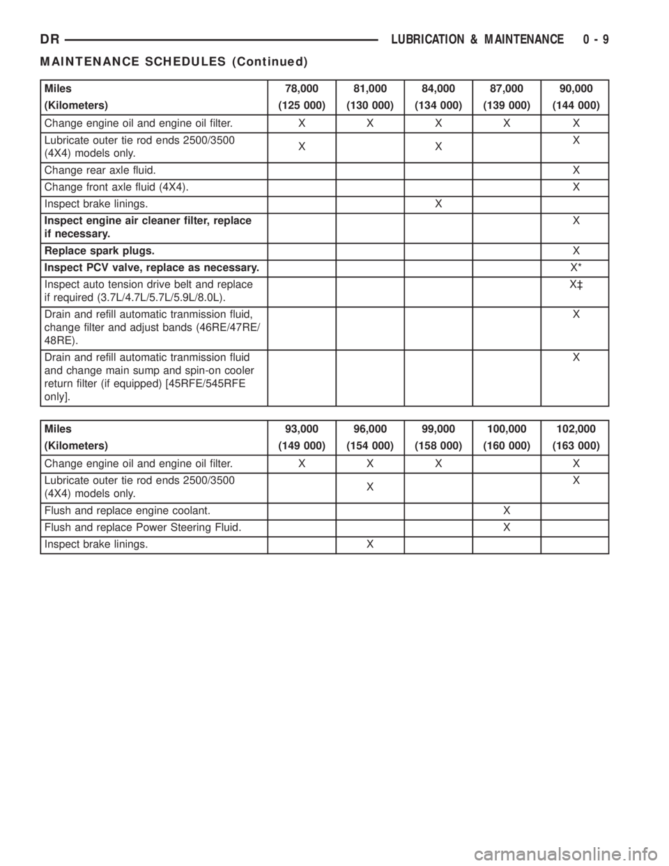
Miles 78,000 81,000 84,000 87,000 90,000
(Kilometers) (125 000) (130 000) (134 000) (139 000) (144 000)
Change engine oil and engine oil filter.XXXX X
Lubricate outer tie rod ends 2500/3500
(4X4) models only.XXX
Change rear axle fluid.X
Change front axle fluid (4X4).X
Inspect brake linings. X
Inspect engine air cleaner filter, replace
if necessary.X
Replace spark plugs.X
Inspect PCV valve, replace as necessary.X*
Inspect auto tension drive belt and replace
if required (3.7L/4.7L/5.7L/5.9L/8.0L).X³
Drain and refill automatic tranmission fluid,
change filter and adjust bands (46RE/47RE/
48RE).X
Drain and refill automatic tranmission fluid
and change main sump and spin-on cooler
return filter (if equipped) [45RFE/545RFE
only].X
Miles 93,000 96,000 99,000 100,000 102,000
(Kilometers) (149 000) (154 000) (158 000) (160 000) (163 000)
Change engine oil and engine oil filter. X X X X
Lubricate outer tie rod ends 2500/3500
(4X4) models only.XX
Flush and replace engine coolant. X
Flush and replace Power Steering Fluid. X
Inspect brake linings. X
DRLUBRICATION & MAINTENANCE 0 - 9
MAINTENANCE SCHEDULES (Continued)
Page 25 of 2895
![DODGE RAM 2003 Service Repair Manual Miles 72,000 78,000 84,000 90,000 96,000 100,000
(Kilometers) (115 000) (125 000) (134 000) (144 000) (154 000) (160 000)
[Months] [72] [78] [84] [90] [96]
Change engine oil and engine oil filter.XXXX](/img/12/56913/w960_56913-24.png "DODGE RAM 2003 Service Repair Manual Miles 72,000 78,000 84,000 90,000 96,000 100,000
(Kilometers) (115 000) (125 000) (134 000) (144 000) (154 000) (160 000)
[Months] [72] [78] [84] [90] [96]
Change engine oil and engine oil filter.XXXX")
Miles 72,000 78,000 84,000 90,000 96,000 100,000
(Kilometers) (115 000) (125 000) (134 000) (144 000) (154 000) (160 000)
[Months] [72] [78] [84] [90] [96]
Change engine oil and engine oil filter.XXXXX
Lubricate outer tie rod ends 2500/3500
(4X4) models only.XXXXX
Drain and refill transfer case fluid. X
Flush and replace engine coolant, if not
done at 60 mos.X
Flush and replace Power Steering Fluid.X
Inspect brake linings. X X
Replace engine air cleaner filter.X
Replace spark plugs.X
Replace ignition cables (5.7L/5.9L/
8.0L).X
Inspect PCV valve, replace as
necessary.X*
Inspect auto tension drive belt and
replace if required (3.7L/4.7L/5.7L/5.9L/
8.0L).X
Drain and refill automatic tranmission
fluid, change filter and adjust bands
(46RE/47RE/48RE).X
Drain and refill automatic tranmission
fluid and change main sump filter and
spin-on cooler return filter (if equipped)
[45RFE/545RFE only].X
Miles 102,000 108,000 114,000 120,000
(Kilometers) (163 000) (173 000) (182 000) (192 000)
[Months] [102] [108] [114] [120]
Change engine oil and engine oil filter. X X X X
Check transfer case fluid level.X
Lubricate outer tie rod ends 2500/3500 (4X4) models only. X X X X
Inspect brake linings. X
Inspect auto tension drive belt and replace if required
(3.7L/4.7L/5.7L/5.9L/8.0L).X³X³
Replace engine air cleaner filter.X
Replace spark plugs.X
* This maintenance is recommended by the manu-
facture to the owner but is not required to maintain
the emissions warranty.
³ This maintenance is not required if previously
replaced.
Inspection and service should also be performed
anytime a malfunction is observed or suspected.
Retain all receipts.WARNING: You can be badly injured working on or
around a motor vehicle. Do only that service work
for which you have the knowledge and the right
equipment. If you have any doubt about your ability
to perform a service job, take your vehicle to a
competent mechanic.
0 - 12 LUBRICATION & MAINTENANCEDR
MAINTENANCE SCHEDULES (Continued)
Page 91 of 2895
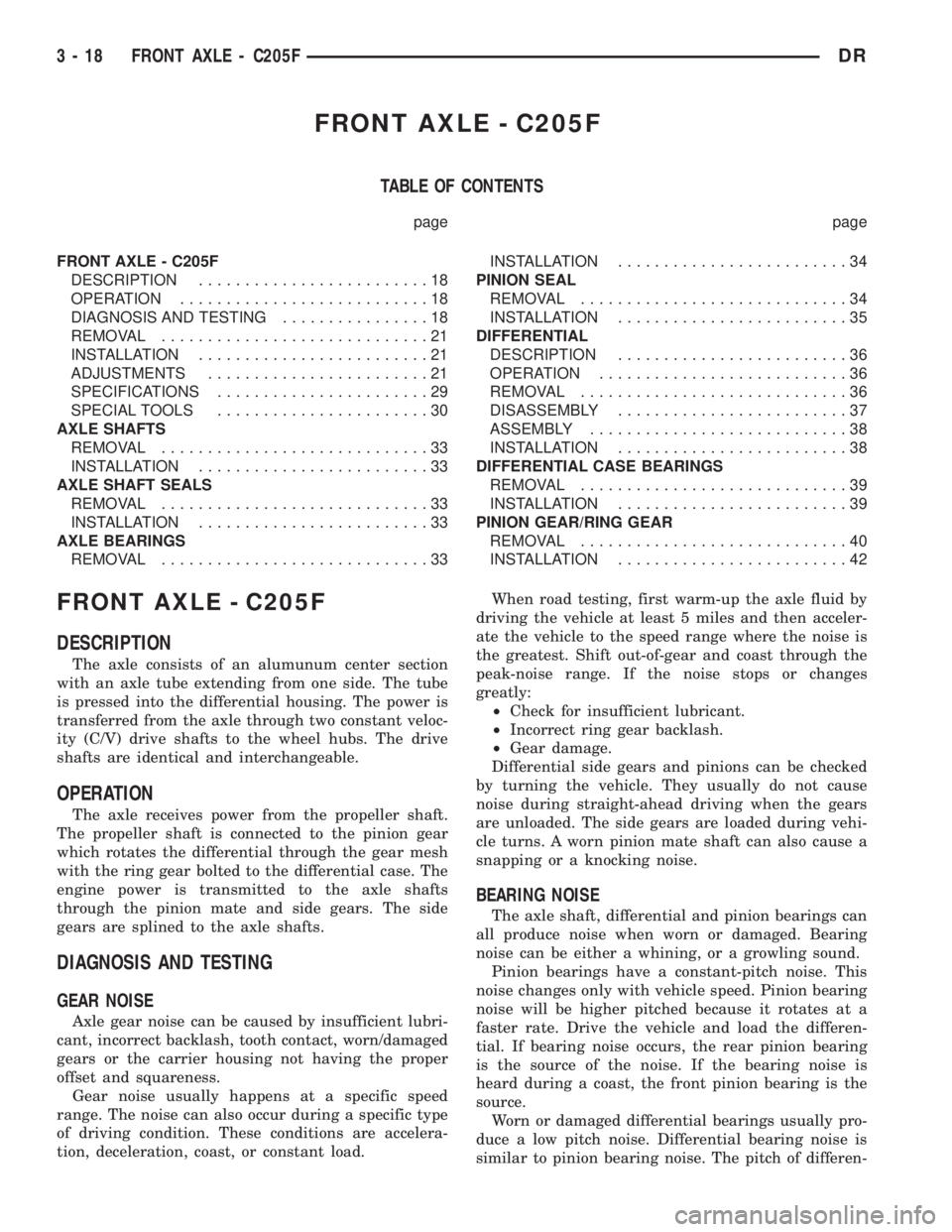
FRONT AXLE - C205F
TABLE OF CONTENTS
page page
FRONT AXLE - C205F
DESCRIPTION.........................18
OPERATION...........................18
DIAGNOSIS AND TESTING................18
REMOVAL.............................21
INSTALLATION.........................21
ADJUSTMENTS........................21
SPECIFICATIONS.......................29
SPECIAL TOOLS.......................30
AXLE SHAFTS
REMOVAL.............................33
INSTALLATION.........................33
AXLE SHAFT SEALS
REMOVAL.............................33
INSTALLATION.........................33
AXLE BEARINGS
REMOVAL.............................33INSTALLATION.........................34
PINION SEAL
REMOVAL.............................34
INSTALLATION.........................35
DIFFERENTIAL
DESCRIPTION.........................36
OPERATION...........................36
REMOVAL.............................36
DISASSEMBLY.........................37
ASSEMBLY............................38
INSTALLATION.........................38
DIFFERENTIAL CASE BEARINGS
REMOVAL.............................39
INSTALLATION.........................39
PINION GEAR/RING GEAR
REMOVAL.............................40
INSTALLATION.........................42
FRONT AXLE - C205F
DESCRIPTION
The axle consists of an alumunum center section
with an axle tube extending from one side. The tube
is pressed into the differential housing. The power is
transferred from the axle through two constant veloc-
ity (C/V) drive shafts to the wheel hubs. The drive
shafts are identical and interchangeable.
OPERATION
The axle receives power from the propeller shaft.
The propeller shaft is connected to the pinion gear
which rotates the differential through the gear mesh
with the ring gear bolted to the differential case. The
engine power is transmitted to the axle shafts
through the pinion mate and side gears. The side
gears are splined to the axle shafts.
DIAGNOSIS AND TESTING
GEAR NOISE
Axle gear noise can be caused by insufficient lubri-
cant, incorrect backlash, tooth contact, worn/damaged
gears or the carrier housing not having the proper
offset and squareness.
Gear noise usually happens at a specific speed
range. The noise can also occur during a specific type
of driving condition. These conditions are accelera-
tion, deceleration, coast, or constant load.When road testing, first warm-up the axle fluid by
driving the vehicle at least 5 miles and then acceler-
ate the vehicle to the speed range where the noise is
the greatest. Shift out-of-gear and coast through the
peak-noise range. If the noise stops or changes
greatly:
²Check for insufficient lubricant.
²Incorrect ring gear backlash.
²Gear damage.
Differential side gears and pinions can be checked
by turning the vehicle. They usually do not cause
noise during straight-ahead driving when the gears
are unloaded. The side gears are loaded during vehi-
cle turns. A worn pinion mate shaft can also cause a
snapping or a knocking noise.
BEARING NOISE
The axle shaft, differential and pinion bearings can
all produce noise when worn or damaged. Bearing
noise can be either a whining, or a growling sound.
Pinion bearings have a constant-pitch noise. This
noise changes only with vehicle speed. Pinion bearing
noise will be higher pitched because it rotates at a
faster rate. Drive the vehicle and load the differen-
tial. If bearing noise occurs, the rear pinion bearing
is the source of the noise. If the bearing noise is
heard during a coast, the front pinion bearing is the
source.
Worn or damaged differential bearings usually pro-
duce a low pitch noise. Differential bearing noise is
similar to pinion bearing noise. The pitch of differen-
3 - 18 FRONT AXLE - C205FDR
Page 118 of 2895
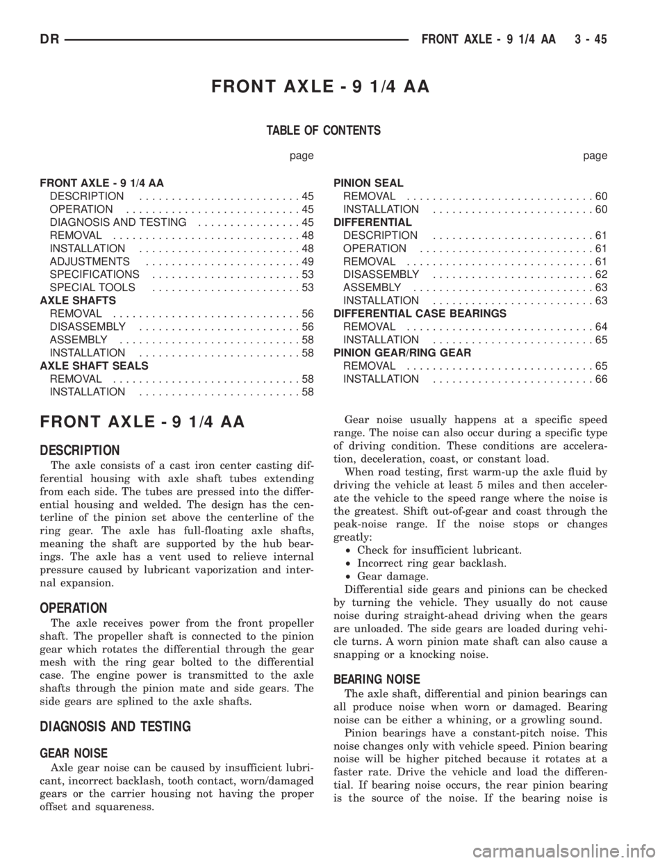
FRONT AXLE - 9 1/4 AA
TABLE OF CONTENTS
page page
FRONT AXLE - 9 1/4 AA
DESCRIPTION.........................45
OPERATION...........................45
DIAGNOSIS AND TESTING................45
REMOVAL.............................48
INSTALLATION.........................48
ADJUSTMENTS........................49
SPECIFICATIONS.......................53
SPECIAL TOOLS.......................53
AXLE SHAFTS
REMOVAL.............................56
DISASSEMBLY.........................56
ASSEMBLY............................58
INSTALLATION.........................58
AXLE SHAFT SEALS
REMOVAL.............................58
INSTALLATION.........................58PINION SEAL
REMOVAL.............................60
INSTALLATION.........................60
DIFFERENTIAL
DESCRIPTION.........................61
OPERATION...........................61
REMOVAL.............................61
DISASSEMBLY.........................62
ASSEMBLY............................63
INSTALLATION.........................63
DIFFERENTIAL CASE BEARINGS
REMOVAL.............................64
INSTALLATION.........................65
PINION GEAR/RING GEAR
REMOVAL.............................65
INSTALLATION.........................66
FRONT AXLE - 9 1/4 AA
DESCRIPTION
The axle consists of a cast iron center casting dif-
ferential housing with axle shaft tubes extending
from each side. The tubes are pressed into the differ-
ential housing and welded. The design has the cen-
terline of the pinion set above the centerline of the
ring gear. The axle has full-floating axle shafts,
meaning the shaft are supported by the hub bear-
ings. The axle has a vent used to relieve internal
pressure caused by lubricant vaporization and inter-
nal expansion.
OPERATION
The axle receives power from the front propeller
shaft. The propeller shaft is connected to the pinion
gear which rotates the differential through the gear
mesh with the ring gear bolted to the differential
case. The engine power is transmitted to the axle
shafts through the pinion mate and side gears. The
side gears are splined to the axle shafts.
DIAGNOSIS AND TESTING
GEAR NOISE
Axle gear noise can be caused by insufficient lubri-
cant, incorrect backlash, tooth contact, worn/damaged
gears or the carrier housing not having the proper
offset and squareness.Gear noise usually happens at a specific speed
range. The noise can also occur during a specific type
of driving condition. These conditions are accelera-
tion, deceleration, coast, or constant load.
When road testing, first warm-up the axle fluid by
driving the vehicle at least 5 miles and then acceler-
ate the vehicle to the speed range where the noise is
the greatest. Shift out-of-gear and coast through the
peak-noise range. If the noise stops or changes
greatly:
²Check for insufficient lubricant.
²Incorrect ring gear backlash.
²Gear damage.
Differential side gears and pinions can be checked
by turning the vehicle. They usually do not cause
noise during straight-ahead driving when the gears
are unloaded. The side gears are loaded during vehi-
cle turns. A worn pinion mate shaft can also cause a
snapping or a knocking noise.
BEARING NOISE
The axle shaft, differential and pinion bearings can
all produce noise when worn or damaged. Bearing
noise can be either a whining, or a growling sound.
Pinion bearings have a constant-pitch noise. This
noise changes only with vehicle speed. Pinion bearing
noise will be higher pitched because it rotates at a
faster rate. Drive the vehicle and load the differen-
tial. If bearing noise occurs, the rear pinion bearing
is the source of the noise. If the bearing noise is
DRFRONT AXLE - 9 1/4 AA 3 - 45
Page 142 of 2895
REAR AXLE-91/4
TABLE OF CONTENTS
page page
REAR AXLE-91/4
DESCRIPTION.........................69
OPERATION...........................69
DIAGNOSIS AND TESTING................69
REMOVAL.............................74
INSTALLATION.........................74
ADJUSTMENTS........................74
SPECIFICATIONS.......................79
SPECIAL TOOLS.......................80
AXLE SHAFTS
REMOVAL.............................83
INSTALLATION.........................83
AXLE SHAFT SEALS
REMOVAL.............................84
INSTALLATION.........................84
AXLE BEARINGS
REMOVAL.............................84
INSTALLATION.........................84
PINION SEAL
REMOVAL.............................85INSTALLATION.........................85
DIFFERENTIAL
DESCRIPTION.........................86
OPERATION...........................86
REMOVAL.............................86
DISASSEMBLY.........................88
ASSEMBLY............................88
INSTALLATION.........................88
DIFFERENTIAL-TRAC-LOK
DESCRIPTION.........................89
OPERATION...........................89
DIAGNOSIS AND TESTING................89
DISASSEMBLY.........................90
ASSEMBLY............................92
DIFFERENTIAL CASE BEARINGS
REMOVAL.............................93
INSTALLATION.........................94
PINION GEAR/RING GEAR/TONE RING
REMOVAL.............................94
INSTALLATION.........................96
REAR AXLE-91/4
DESCRIPTION
The axle consist of a cast iron center section with
axle tubes extending from either side. The tubes are
pressed into and welded to the differential housing to
form a one-piece axle housing (Fig. 1). The axles are
equipped with semi-floating axle shafts, meaning
vehicle loads are supported by the axle shaft and
bearings. The axle shafts are retained by C-locks in
the differential side gears.
OPERATION
The axle receives power from the propeller shaft.
The propeller shaft is connected to the pinion gear
which rotates the differential through the gear mesh
with the ring gear bolted to the differential case. The
engine power is transmitted to the axle shafts
through the pinion mate and side gears. The side
gears are splined to the axle shafts.
DIAGNOSIS AND TESTING
GEAR NOISE
Axle gear noise can be caused by insufficient lubri-
cant, incorrect backlash, incorrect pinion depth, toothcontact, worn/damaged gears, or the carrier housing
not having the proper offset and squareness.
Gear noise usually happens at a specific speed
range. The noise can also occur during a specific type
of driving condition. These conditions are accelera-
tion, deceleration, coast, or constant load.
When road testing, first warm-up the axle fluid by
driving the vehicle at least 5 miles and then acceler-
ate the vehicle to the speed range where the noise is
the greatest. Shift out-of-gear and coast through the
peak-noise range. If the noise stops or changes
greatly:
²Check for insufficient lubricant.
²Incorrect ring gear backlash.
²Gear damage.
Differential side gears and pinions can be checked
by turning the vehicle. They usually do not cause
noise during straight-ahead driving when the gears
are unloaded. The side gears are loaded during vehi-
cle turns. A worn pinion shaft can also cause a snap-
ping or a knocking noise.
BEARING NOISE
The axle shaft, differential and pinion bearings can
all produce noise when worn or damaged. Bearing
noise can be either a whining, or a growling sound.
Pinion bearings have a constant-pitch noise. This
noise changes only with vehicle speed. Pinion bearing
DRREAR AXLE - 9 1/4 3 - 69