Power DODGE RAM 2003 Service User Guide
[x] Cancel search | Manufacturer: DODGE, Model Year: 2003, Model line: RAM, Model: DODGE RAM 2003Pages: 2895, PDF Size: 83.15 MB
Page 162 of 2895
CAUTION: If cover is not installed within 3 to 5 min-
utes, the cover must be cleaned and new RTV
applied or adhesion quality will be compromised.
(8) Install the cover and any identification tag and
tighten cover bolts to 41 N´m (30 ft. lbs.).
(9) Fill differential with lubricant to bottom of the
fill plug hole. Refer to the Lubricant Specifications
for the correct quantity and type.
NOTE: Trac-lokŸ differential equipped vehicles
should be road tested by making 10 to 12 slow fig-
ure-eight turns. This maneuver will pump the lubri-
cant through the clutch discs to eliminate a
possible chatter noise complaint.
DIFFERENTIAL-TRAC-LOK
DESCRIPTION
The optional Trac-Loktdifferential case has a one-
piece design and the similar internal components as
a standard differential, plus two clutch disc pack-
s.The differential pinion mate shaft is retained with
a threaded pin. Differential bearing preload and ring
gear backlash are set and maintained by threaded
adjusters at the outside of the differential housing.
Pinion bearing preload is set and maintained by the
use of a collapsible spacer. The removable differential
cover provides a means for inspection and service.
OPERATION
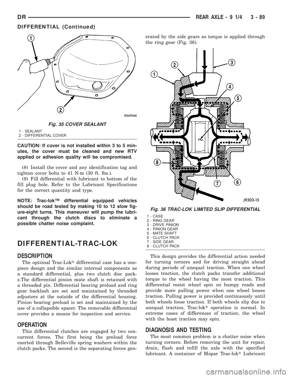
This differential clutches are engaged by two con-
current forces. The first being the preload force
exerted through Belleville spring washers within the
clutch packs. The second is the separating forces gen-erated by the side gears as torque is applied through
the ring gear (Fig. 36).
This design provides the differential action needed
for turning corners and for driving straight ahead
during periods of unequal traction. When one wheel
looses traction, the clutch packs transfer additional
torque to the wheel having the most traction. This
differential resist wheel spin on bumpy roads and
provide more pulling power when one wheel looses
traction. Pulling power is provided continuously until
both wheels loose traction. If both wheels slip due to
unequal traction, Trac-loktoperation is normal. In
extreme cases of differences of traction, the wheel
with the least traction may spin.DIAGNOSIS AND TESTING
The most common problem is a chatter noise when
turning corners. Before removing the unit for repair,
drain, flush and refill the axle with the specified
lubricant. A container of Mopar Trac-loktLubricant
Fig. 35 COVER SEALANT
1 - SEALANT
2 - DIFFERENTIAL COVER
Fig. 36 TRAC-LOK LIMITED SLIP DIFFERENTIAL
1 - CASE
2 - RING GEAR
3 - DRIVE PINION
4 - PINION GEAR
5 - MATE SHAFT
6 - CLUTCH PACK
7 - SIDE GEAR
8 - CLUTCH PACK
DRREAR AXLE - 9 1/4 3 - 89
DIFFERENTIAL (Continued)
Page 173 of 2895
REAR AXLE - 10 1/2 AA
TABLE OF CONTENTS
page page
REAR AXLE - 10 1/2 AA
DESCRIPTION........................100
OPERATION..........................100
DIAGNOSIS AND TESTING...............100
REMOVAL............................103
INSTALLATION........................103
ADJUSTMENTS.......................104
SPECIFICATIONS......................108
SPECIAL TOOLS.......................108
AXLE SHAFTS
REMOVAL............................111
INSTALLATION........................111
AXLE BEARINGS
REMOVAL............................112
INSTALLATION........................112
PINION SEAL
REMOVAL............................113
INSTALLATION........................113
DIFFERENTIAL
DESCRIPTION........................114OPERATION..........................114
REMOVAL............................115
DISASSEMBLY........................115
ASSEMBLY...........................116
INSTALLATION........................117
DIFFERENTIAL TRAC-RITE
DESCRIPTION........................118
OPERATION..........................118
DISASSEMBLY........................118
CLEANING...........................119
INSPECTION..........................119
ASSEMBLY...........................120
DIFFERENTIAL CASE BEARINGS
REMOVAL............................121
INSTALLATION........................121
PINION GEAR/RING GEAR/TONE RING
REMOVAL............................122
INSTALLATION........................123
REAR AXLE - 10 1/2 AA
DESCRIPTION
The axle consists of a cast iron center casting dif-
ferential housing with axle shaft tubes extending
from each side. The tubes are pressed into the differ-
ential housing and welded. The design has the cen-
terline of the pinion set below the centerline of the
ring gear. The axle is a full floating axle where the
loads are supported by the axle housing tubes. The
axle has a vent used to relieve internal pressure
caused by lubricant vaporization and internal expan-
sion.
OPERATION
The axle receives power from the propeller shaft.
The propeller shaft is connected to the pinion gear
which rotates the differential through the gear mesh
with the ring gear bolted to the differential case. The
engine power is transmitted to the axle shafts
through the pinion mate and side gears. The side
gears are splined to the axle shafts.
DIAGNOSIS AND TESTING
GEAR NOISE
Axle gear noise can be caused by insufficient lubri-
cant, incorrect backlash, incorrect pinion depth, tooth
contact, worn/damaged gears, or the carrier housing
not having the proper offset and squareness.
Gear noise usually happens at a specific speed
range. The noise can also occur during a specific type
of driving condition. These conditions are accelera-
tion, deceleration, coast, or constant load.
When road testing, first warm-up the axle fluid by
driving the vehicle at least 5 miles and then acceler-
ate the vehicle to the speed range where the noise is
the greatest. Shift out-of-gear and coast through the
peak-noise range. If the noise stops or changes
greatly:
²Check for insufficient lubricant.
²Incorrect ring gear backlash.
²Gear damage.
Differential side gears and pinions can be checked
by turning the vehicle. They usually do not cause
noise during straight-ahead driving when the gears
are unloaded. The side gears are loaded during vehi-
cle turns. A worn pinion shaft can also cause a snap-
ping or a knocking noise.
3 - 100 REAR AXLE - 10 1/2 AADR
Page 191 of 2895
(8) Install ring gear side adjuster lock and bolt. Do
not tighten adjuster lock bolt at this time.
(9) Tighten pinion gear side adjuster firmly
against the differential case bearing cup.
(10) Rotate the pinion several times to seat the dif-
ferential bearings.
(11) Loosen pinion gear side adjuster until it is no
longer in contact with the bearing cup.
(12) Tighten pinion gear side adjuster until it just
makes contact with the bearing cup.
(13) Tighten pinion gear side adjuster an addi-
tional:
²New Bearings6 Adjuster Holes
²Original Bearings4 Adjuster Holes
(14) Install pinion gear side adjuster lock and bolt.
Do not tighten adjuster lock bolt at this time.
(15) Tighten bearing cap bolts to 165 N´m (122 ft.
lbs.).
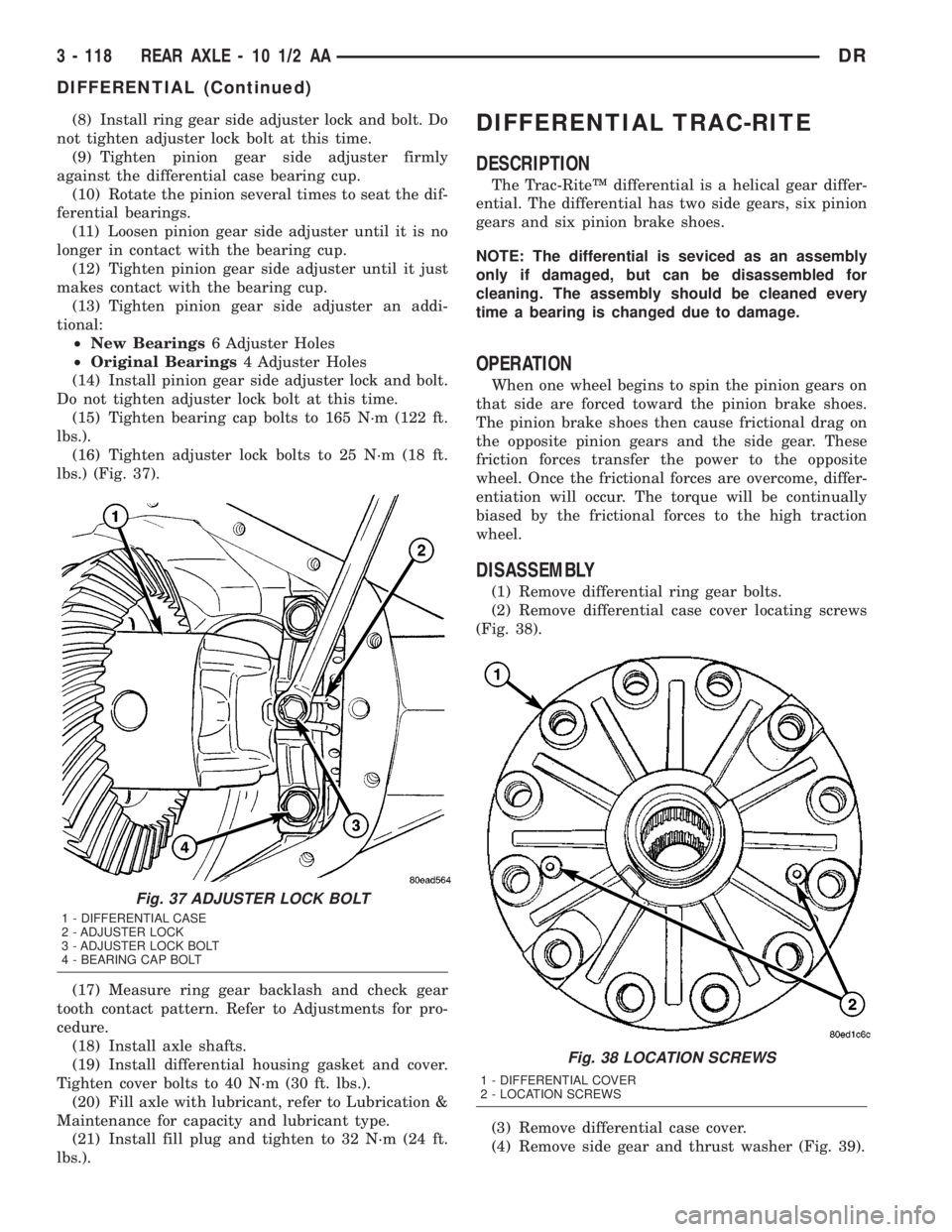
(16) Tighten adjuster lock bolts to 25 N´m (18 ft.
lbs.) (Fig. 37).
(17) Measure ring gear backlash and check gear
tooth contact pattern. Refer to Adjustments for pro-
cedure.
(18) Install axle shafts.
(19) Install differential housing gasket and cover.
Tighten cover bolts to 40 N´m (30 ft. lbs.).
(20) Fill axle with lubricant, refer to Lubrication &
Maintenance for capacity and lubricant type.
(21) Install fill plug and tighten to 32 N´m (24 ft.
lbs.).DIFFERENTIAL TRAC-RITE
DESCRIPTION
The Trac-RiteŸ differential is a helical gear differ-
ential. The differential has two side gears, six pinion
gears and six pinion brake shoes.
NOTE: The differential is seviced as an assembly
only if damaged, but can be disassembled for
cleaning. The assembly should be cleaned every
time a bearing is changed due to damage.
OPERATION
When one wheel begins to spin the pinion gears on
that side are forced toward the pinion brake shoes.
The pinion brake shoes then cause frictional drag on
the opposite pinion gears and the side gear. These
friction forces transfer the power to the opposite
wheel. Once the frictional forces are overcome, differ-
entiation will occur. The torque will be continually
biased by the frictional forces to the high traction
wheel.
DISASSEMBLY
(1) Remove differential ring gear bolts.
(2) Remove differential case cover locating screws
(Fig. 38).
(3) Remove differential case cover.
(4) Remove side gear and thrust washer (Fig. 39).
Fig. 37 ADJUSTER LOCK BOLT
1 - DIFFERENTIAL CASE
2 - ADJUSTER LOCK
3 - ADJUSTER LOCK BOLT
4 - BEARING CAP BOLT
Fig. 38 LOCATION SCREWS
1 - DIFFERENTIAL COVER
2 - LOCATION SCREWS
3 - 118 REAR AXLE - 10 1/2 AADR
DIFFERENTIAL (Continued)
Page 200 of 2895
REAR AXLE - 11 1/2 AA
TABLE OF CONTENTS
page page
REAR AXLE - 11 1/2 AA
DESCRIPTION........................127
OPERATION..........................127
DIAGNOSIS AND TESTING...............127
REMOVAL............................130
INSTALLATION........................130
ADJUSTMENTS.......................131
SPECIFICATIONS......................135
SPECIAL TOOLS.......................135
AXLE SHAFTS
REMOVAL............................138
INSTALLATION........................138
AXLE BEARINGS
REMOVAL............................138
INSTALLATION........................139
PINION SEAL
REMOVAL............................140
INSTALLATION........................140
DIFFERENTIAL
DESCRIPTION........................141OPERATION..........................141
REMOVAL............................142
DISASSEMBLY........................142
ASSEMBLY...........................143
INSTALLATION........................144
DIFFERENTIAL TRAC-RITE
DESCRIPTION........................145
OPERATION..........................145
DISASSEMBLY........................145
CLEANING...........................146
INSPECTION.........................146
ASSEMBLY...........................147
DIFFERENTIAL CASE BEARINGS
REMOVAL............................148
INSTALLATION........................148
PINION GEAR/RING GEAR/TONE RING
REMOVAL............................149
INSTALLATION........................150
REAR AXLE - 11 1/2 AA
DESCRIPTION
The axle consists of a cast iron center casting dif-
ferential housing with axle shaft tubes extending
from each side. The tubes are pressed into the differ-
ential housing and welded. The design has the cen-
terline of the pinion set below the centerline of the
ring gear. The axle is a full floating axle where the
loads are supported by the axle housing tubes. The
axle has a vent used to relieve internal pressure
caused by lubricant vaporization and internal expan-
sion.
OPERATION
The axle receives power from the propeller shaft.
The propeller shaft is connected to the pinion gear
which rotates the differential through the gear mesh
with the ring gear bolted to the differential case. The
engine power is transmitted to the axle shafts
through the pinion mate and side gears. The side
gears are splined to the axle shafts.
DIAGNOSIS AND TESTING
GEAR NOISE
Axle gear noise can be caused by insufficient lubri-
cant, incorrect backlash, incorrect pinion depth, tooth
contact, worn/damaged gears, or the carrier housing
not having the proper offset and squareness.
Gear noise usually happens at a specific speed
range. The noise can also occur during a specific type
of driving condition. These conditions are accelera-
tion, deceleration, coast, or constant load.
When road testing, first warm-up the axle fluid by
driving the vehicle at least 5 miles and then acceler-
ate the vehicle to the speed range where the noise is
the greatest. Shift out-of-gear and coast through the
peak-noise range. If the noise stops or changes
greatly:
²Check for insufficient lubricant.
²Incorrect ring gear backlash.
²Gear damage.
Differential side gears and pinions can be checked
by turning the vehicle. They usually do not cause
noise during straight-ahead driving when the gears
are unloaded. The side gears are loaded during vehi-
cle turns. A worn pinion shaft can also cause a snap-
ping or a knocking noise.
DRREAR AXLE - 11 1/2 AA 3 - 127
Page 218 of 2895
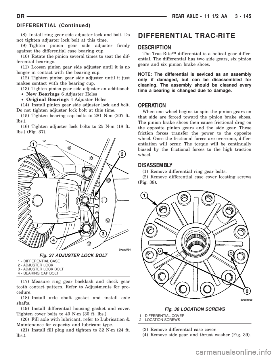
(8) Install ring gear side adjuster lock and bolt. Do
not tighten adjuster lock bolt at this time.
(9) Tighten pinion gear side adjuster firmly
against the differential case bearing cup.
(10) Rotate the pinion several times to seat the dif-
ferential bearings.
(11) Loosen pinion gear side adjuster until it is no
longer in contact with the bearing cup.
(12) Tighten pinion gear side adjuster until it just
makes contact with the bearing cup.
(13)
Tighten pinion gear side adjuster an additional:
²New Bearings6 Adjuster Holes
²Original Bearings4 Adjuster Holes
(14) Install pinion gear side adjuster lock and bolt.
Do not tighten adjuster lock bolt at this time.
(15) Tighten bearing cap bolts to 281 N´m (207 ft.
lbs.).
(16) Tighten adjuster lock bolts to 25 N´m (18 ft.
lbs.) (Fig. 37).
(17) Measure ring gear backlash and check gear
tooth contact pattern. Refer to Adjustments for pro-
cedure.
(18) Install axle shaft gasket and install axle
shafts.
(19) Install differential housing gasket and cover.
Tighten cover bolts to 40 N´m (30 ft. lbs.).
(20) Fill axle with lubricant, refer to Lubrication &
Maintenance for capacity and lubricant type.
(21) Install fill plug and tighten to 32 N´m (24 ft.
lbs.).
DIFFERENTIAL TRAC-RITE
DESCRIPTION
The Trac-RiteŸ differential is a helical gear differ-
ential. The differential has two side gears, six pinion
gears and six pinion brake shoes.
NOTE: The differential is seviced as an assembly
only if damaged, but can be disassembled for
cleaning. The assembly should be cleaned every
time a bearing is changed due to damage.
OPERATION
When one wheel begins to spin the pinion gears on
that side are forced toward the pinion brake shoes.
The pinion brake shoes then cause frictional drag on
the opposite pinion gears and the side gear. These
friction forces transfer the power to the opposite
wheel. Once the frictional forces are overcome, differ-
entiation will occur. The torque will be continually
biased by the frictional forces to the high traction
wheel.
DISASSEMBLY
(1) Remove differential ring gear bolts.
(2) Remove differential case cover locating screws
(Fig. 38).
(3) Remove differential case cover.
(4) Remove side gear and thrust washer (Fig. 39).
Fig. 37 ADJUSTER LOCK BOLT
1 - DIFFERENTIAL CASE
2 - ADJUSTER LOCK
3 - ADJUSTER LOCK BOLT
4 - BEARING CAP BOLT
Fig. 38 LOCATION SCREWS
1 - DIFFERENTIAL COVER
2 - LOCATION SCREWS
DRREAR AXLE - 11 1/2 AA 3 - 145
DIFFERENTIAL (Continued)
Page 229 of 2895
DIAGNOSIS AND TESTING - MASTER
CYLINDER/POWER BOOSTER...........20
STANDARD PROCEDURE - MASTER
CYLINDER BLEEDING..................20
REMOVAL
REMOVAL - ALL EXCEPT HYDROBOOST . . . 21
REMOVAL - HYDROBOOST.............21
INSTALLATION
INSTALLATION - ALL EXCEPT
HYDROBOOST.......................22
INSTALLATION - HYDROBOOST..........22
PEDAL
DESCRIPTION.........................22
OPERATION...........................22
REMOVAL.............................23
INSTALLATION.........................23
ADJUSTABLE PEDAL MOTOR
DESCRIPTION.........................24
REMOVAL.............................24
INSTALLATION.........................24
POWER BRAKE BOOSTER
DESCRIPTION.........................25
OPERATION...........................25
REMOVAL.............................25
INSTALLATION.........................25
HYDRO-BOOST BRAKE BOOSTER
DIAGNOSIS AND TESTING - HYDRAULIC
BOOSTER...........................25
STANDARD PROCEDURE - BLEEDING......27
REMOVAL.............................27
INSTALLATION.........................27
ROTORS
REMOVAL
REMOVAL - REAR.....................28
REMOVAL - FRONT....................28
INSTALLATION
INSTALLATION - REAR.................28
INSTALLATION - FRONT................29SUPPORT PLATE
REMOVAL.............................29
INSTALLATION.........................29
PARKING BRAKE
DESCRIPTION.........................30
OPERATION...........................30
CABLES
REMOVAL
REMOVAL - FRONT PARKING BRAKE
CABLE..............................31
REMOVAL - REAR PARK BRAKE CABLE . . . 31
REMOVAL - RIGHT REAR CABLE.........31
REMOVAL - LEFT REAR CABLE..........32
INSTALLATION
INSTALLATION - FRONT PARKING BRAKE
CABLE..............................32
INSTALLATION - REAR PARK BRAKE
CABLE..............................32
INSTALLATION - RIGHT REAR CABLE.....32
INSTALLATION - LEFT REAR CABLE......33
SHOES
REMOVAL.............................33
CLEANING - REAR DRUM IN HAT BRAKE....33
INSPECTION - REAR DRUM IN HAT BRAKE . . 33
INSTALLATION.........................34
ADJUSTMENTS
ADJUSTMENT - PARKING BRAKE SHOES . . 34
ADJUSTMENT - WITH ADJUSTING TOOL . . . 36
PEDAL
REMOVAL.............................36
INSTALLATION.........................36
CABLE TENSIONER
ADJUSTMENTS
ADJUSTMENT........................37
RELEASE HANDLE
REMOVAL.............................38
INSTALLATION.........................38
BRAKES - BASE
DIAGNOSIS AND TESTING - BASE BRAKE
SYSTEM
Base brake components consist of the brake shoes,
calipers, wheel cylinders, brake drums, rotors, brake
lines, master cylinder, booster, and parking brake
components.
Brake diagnosis involves determining if the prob-
lem is related to a mechanical, hydraulic, or vacuum
operated component.
The first diagnosis step is the preliminary check.
PRELIMINARY BRAKE CHECK
(1) Check condition of tires and wheels. Damaged
wheels and worn, damaged, or underinflated tires
can cause pull, shudder, vibration, and a condition
similar to grab.(2) If complaint was based on noise when braking,
check suspension components. Jounce front and rear
of vehicle and listen for noise that might be caused
by loose, worn or damaged suspension or steering
components.
(3) Inspect brake fluid level and condition. Note
that the brake reservoir fluid level will decrease in
proportion to normal lining wear.Also note that
brake fluid tends to darken over time. This is
normal and should not be mistaken for contam-
ination.
(a) If fluid level is abnormally low, look for evi-
dence of leaks at calipers, wheel cylinders, brake
lines, and master cylinder.
(b) If fluid appears contaminated, drain out a
sample to examine. System will have to be flushed
if fluid is separated into layers, or contains a sub-
stance other than brake fluid. The system seals
5 - 2 BRAKES - BASEDR
Page 230 of 2895
and cups will also have to be replaced after flush-
ing. Use clean brake fluid to flush the system.
(4) Check parking brake operation. Verify free
movement and full release of cables and pedal. Also
note if vehicle was being operated with parking
brake partially applied.
(5) Check brake pedal operation. Verify that pedal
does not bind and has adequate free play. If pedal
lacks free play, check pedal and power booster for
being loose or for bind condition. Do not road test
until condition is corrected.
(6) Check booster vacuum check valve and hose.
(7) If components checked appear OK, road test
the vehicle.
ROAD TESTING
(1) If complaint involved low brake pedal, pump
pedal and note if it comes back up to normal height.
(2) Check brake pedal response with transmission
in Neutral and engine running. Pedal should remain
firm under constant foot pressure.
(3) During road test, make normal and firm brake
stops in 25-40 mph range. Note faulty brake opera-
tion such as low pedal, hard pedal, fade, pedal pulsa-
tion, pull, grab, drag, noise, etc.
(4) Attempt to stop the vehicle with the parking
brake only and note grab, drag, noise, etc.
PEDAL FALLS AWAY
A brake pedal that falls away under steady foot
pressure is generally the result of a system leak. The
leak point could be at a brake line, fitting, hose, or
caliper/wheel cylinder. If leakage is severe, fluid will
be evident at or around the leaking component.
Internal leakage (seal by-pass) in the master cylin-
der caused by worn or damaged piston cups, may
also be the problem cause.
An internal leak in the ABS or RWAL system may
also be the problem with no physical evidence.
LOW PEDAL
If a low pedal is experienced, pump the pedal sev-
eral times. If the pedal comes back up worn linings,
rotors, drums, or rear brakes out of adjustment are
the most likely causes. The proper course of action is
to inspect and replace all worn component and make
the proper adjustments.
SPONGY PEDAL
A spongy pedal is most often caused by air in the
system. However, thin brake drums or substandard
brake lines and hoses can also cause a spongy pedal.
The proper course of action is to bleed the system,
and replace thin drums and substandard quality
brake hoses if suspected.HARD PEDAL OR HIGH PEDAL EFFORT
A hard pedal or high pedal effort may be due to
lining that is water soaked, contaminated, glazed, or
badly worn. The power booster or check valve could
also be faulty.
PEDAL PULSATION
Pedal pulsation is caused by components that are
loose, or beyond tolerance limits.
The primary cause of pulsation are disc brake
rotors with excessive lateral runout or thickness vari-
ation, or out of round brake drums. Other causes are
loose wheel bearings or calipers and worn, damaged
tires.
NOTE: Some pedal pulsation may be felt during
ABS activation.
BRAKE DRAG
Brake drag occurs when the lining is in constant
contact with the rotor or drum. Drag can occur at one
wheel, all wheels, fronts only, or rears only.
Drag is a product of incomplete brake shoe release.
Drag can be minor or severe enough to overheat the
linings, rotors and drums.
Minor drag will usually cause slight surface char-
ring of the lining. It can also generate hard spots in
rotors and drums from the overheat-cool down pro-
cess. In most cases, the rotors, drums, wheels and
tires are quite warm to the touch after the vehicle is
stopped.
Severe drag can char the brake lining all the way
through. It can also distort and score rotors and
drums to the point of replacement. The wheels, tires
and brake components will be extremely hot. In
severe cases, the lining may generate smoke as it
chars from overheating.
Common causes of brake drag are:
²Seized or improperly adjusted parking brake
cables.
²Loose/worn wheel bearing.
²Seized caliper or wheel cylinder piston.
²Caliper binding on corroded bushings or rusted
slide surfaces.
²Loose caliper mounting.
²Drum brake shoes binding on worn/damaged
support plates.
²Mis-assembled components.
²Long booster output rod.
If brake drag occurs at all wheels, the problem
may be related to a blocked master cylinder return
port, or faulty power booster (binds-does not release).
BRAKE FADE
Brake fade is usually a product of overheating
caused by brake drag. However, brake overheating
DRBRAKES - BASE 5 - 3
BRAKES - BASE (Continued)
Page 245 of 2895
(6) Adjust brake shoes to drum with brake gauge
(Refer to 5 - BRAKES/PARKING BRAKE/SHOES -
ADJUSTMENTS).
(7) Install the rotor (Refer to 5 - BRAKES/HY-
DRAULIC/MECHANICAL/ROTORS - INSTALLA-
TION).
(8) Install the caliper adapter (Refer to 5 -
BRAKES/HYDRAULIC/MECHANICAL/DISC
BRAKE CALIPER ADAPTER - INSTALLATION).
(9) Install the caliper (Refer to 5 - BRAKES/HY-
DRAULIC/MECHANICAL/DISC BRAKE CALIPERS
- INSTALLATION).
(10) Install wheel and tire assembly.
FLUID
DIAGNOSIS AND TESTING - BRAKE FLUID
CONTAMINATION
Indications of fluid contamination are swollen or
deteriorated rubber parts.
Swollen rubber parts indicate the presence of
petroleum in the brake fluid.
To test for contamination, put a small amount of
drained brake fluid in clear glass jar. If fluid sepa-
rates into layers, there is mineral oil or other fluid
contamination of the brake fluid.
If brake fluid is contaminated, drain and thor-
oughly flush system. Replace master cylinder, propor-
tioning valve, caliper seals, wheel cylinder seals,
Antilock Brakes hydraulic unit and all hydraulic
fluid hoses.
STANDARD PROCEDURE - BRAKE FLUID
LEVEL
Always clean the master cylinder reservoir and
caps before checking fluid level. If not cleaned, dirt
could enter the fluid.
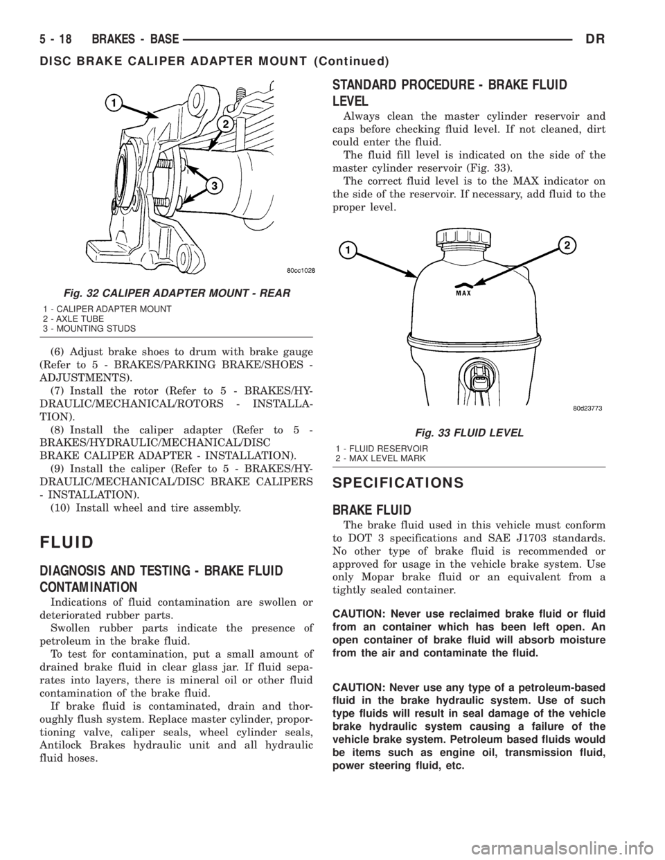
The fluid fill level is indicated on the side of the
master cylinder reservoir (Fig. 33).
The correct fluid level is to the MAX indicator on
the side of the reservoir. If necessary, add fluid to the
proper level.
SPECIFICATIONS
BRAKE FLUID
The brake fluid used in this vehicle must conform
to DOT 3 specifications and SAE J1703 standards.
No other type of brake fluid is recommended or
approved for usage in the vehicle brake system. Use
only Mopar brake fluid or an equivalent from a
tightly sealed container.
CAUTION: Never use reclaimed brake fluid or fluid
from an container which has been left open. An
open container of brake fluid will absorb moisture
from the air and contaminate the fluid.
CAUTION: Never use any type of a petroleum-based
fluid in the brake hydraulic system. Use of such
type fluids will result in seal damage of the vehicle
brake hydraulic system causing a failure of the
vehicle brake system. Petroleum based fluids would
be items such as engine oil, transmission fluid,
power steering fluid, etc.
Fig. 32 CALIPER ADAPTER MOUNT - REAR
1 - CALIPER ADAPTER MOUNT
2 - AXLE TUBE
3 - MOUNTING STUDS
Fig. 33 FLUID LEVEL
1 - FLUID RESERVOIR
2 - MAX LEVEL MARK
5 - 18 BRAKES - BASEDR
DISC BRAKE CALIPER ADAPTER MOUNT (Continued)
Page 247 of 2895
cuit separation in the event of a front or rear brake
malfunction. The reservoir compartments will retain
enough fluid to operate the functioning hydraulic cir-
cuit.
Care must be exercised when removing/installing
the master cylinder connecting lines. The threads in
the cylinder fluid ports can be damaged if care is not
exercised. Start all brake line fittings by hand to
avoid cross threading.
The cylinder reservoir can be replaced when neces-
sary. However, the aluminum body section of the
master cylinder is not a repairable component.
NOTE: If diagnosis indicates that an internal mal-
function has occurred, the aluminum body section
must be replaced as an assembly.
OPERATION
The master cylinder bore contains a primary and
secondary piston. The primary piston supplies
hydraulic pressure to the front brakes. The secondary
piston supplies hydraulic pressure to the rear brakes.
DIAGNOSIS AND TESTING - MASTER
CYLINDER/POWER BOOSTER
(1) Start engine and check booster vacuum hose
connections. A hissing noise indicates vacuum leak.
Correct any vacuum leak before proceeding.
(2) Stop engine and shift transmission into Neu-
tral.
(3) Pump brake pedal until all vacuum reserve in
booster is depleted.
(4) Press and hold brake pedal under light foot
pressure. The pedal should hold firm, if the pedal
falls away master cylinder is faulty (internal leak-
age).
(5) Start engine and note pedal action. It should
fall away slightly under light foot pressure then hold
firm. If no pedal action is discernible, power booster,
vacuum supply, or vacuum check valve is faulty. Pro-
ceed to the POWER BOOSTER VACUUM TEST.
(6) If the POWER BOOSTER VACUUM TEST
passes, rebuild booster vacuum reserve as follows:
Release brake pedal. Increase engine speed to 1500
rpm, close the throttle and immediately turn off igni-
tion to stop engine.
(7) Wait a minimum of 90 seconds and try brake
action again. Booster should provide two or more vac-
uum assisted pedal applications. If vacuum assist is
not provided, booster is faulty.
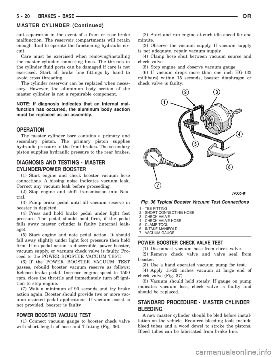
POWER BOOSTER VACUUM TEST
(1) Connect vacuum gauge to booster check valve
with short length of hose and T-fitting (Fig. 36).(2) Start and run engine at curb idle speed for one
minute.
(3) Observe the vacuum supply. If vacuum supply
is not adequate, repair vacuum supply.
(4) Clamp hose shut between vacuum source and
check valve.
(5) Stop engine and observe vacuum gauge.
(6) If vacuum drops more than one inch HG (33
millibars) within 15 seconds, booster diaphragm or
check valve is faulty.
POWER BOOSTER CHECK VALVE TEST
(1) Disconnect vacuum hose from check valve.
(2) Remove check valve and valve seal from
booster.
(3) Use a hand operated vacuum pump for test.
(4) Apply 15-20 inches vacuum at large end of
check valve (Fig. 37).
(5) Vacuum should hold steady. If gauge on pump
indicates vacuum loss, check valve is faulty and
should be replaced.
STANDARD PROCEDURE - MASTER CYLINDER
BLEEDING
A new master cylinder should be bled before instal-
lation on the vehicle. Required bleeding tools include
bleed tubes and a wood dowel to stroke the pistons.
Bleed tubes can be fabricated from brake line.
Fig. 36 Typical Booster Vacuum Test Connections
1 - TEE FITTING
2 - SHORT CONNECTING HOSE
3 - CHECK VALVE
4 - CHECK VALVE HOSE
5 - CLAMP TOOL
6 - INTAKE MANIFOLD
7 - VACUUM GAUGE
5 - 20 BRAKES - BASEDR
MASTER CYLINDER (Continued)
Page 248 of 2895
(1) Mount master cylinder in vise.
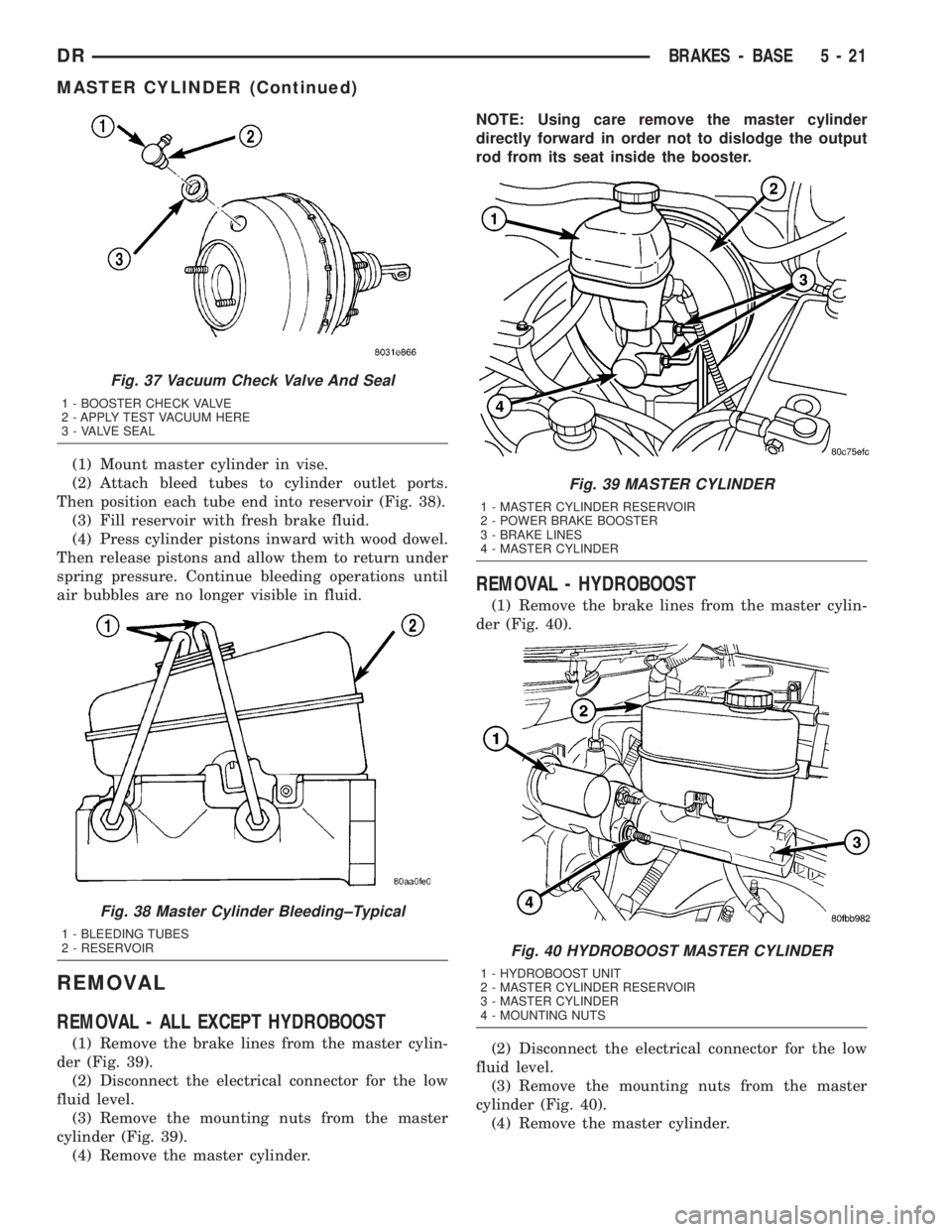
(2) Attach bleed tubes to cylinder outlet ports.
Then position each tube end into reservoir (Fig. 38).
(3) Fill reservoir with fresh brake fluid.
(4) Press cylinder pistons inward with wood dowel.
Then release pistons and allow them to return under
spring pressure. Continue bleeding operations until
air bubbles are no longer visible in fluid.
REMOVAL
REMOVAL - ALL EXCEPT HYDROBOOST
(1) Remove the brake lines from the master cylin-
der (Fig. 39).
(2) Disconnect the electrical connector for the low
fluid level.
(3) Remove the mounting nuts from the master
cylinder (Fig. 39).
(4) Remove the master cylinder.NOTE: Using care remove the master cylinder
directly forward in order not to dislodge the output
rod from its seat inside the booster.
REMOVAL - HYDROBOOST
(1) Remove the brake lines from the master cylin-
der (Fig. 40).
(2) Disconnect the electrical connector for the low
fluid level.
(3) Remove the mounting nuts from the master
cylinder (Fig. 40).
(4) Remove the master cylinder.
Fig. 37 Vacuum Check Valve And Seal
1 - BOOSTER CHECK VALVE
2 - APPLY TEST VACUUM HERE
3 - VALVE SEAL
Fig. 38 Master Cylinder Bleeding±Typical
1 - BLEEDING TUBES
2 - RESERVOIR
Fig. 39 MASTER CYLINDER
1 - MASTER CYLINDER RESERVOIR
2 - POWER BRAKE BOOSTER
3 - BRAKE LINES
4 - MASTER CYLINDER
Fig. 40 HYDROBOOST MASTER CYLINDER
1 - HYDROBOOST UNIT
2 - MASTER CYLINDER RESERVOIR
3 - MASTER CYLINDER
4 - MOUNTING NUTS
DRBRAKES - BASE 5 - 21
MASTER CYLINDER (Continued)