cylinder head gasket DODGE RAM 2003 Service Repair Manual
[x] Cancel search | Manufacturer: DODGE, Model Year: 2003, Model line: RAM, Model: DODGE RAM 2003Pages: 2895, PDF Size: 83.15 MB
Page 293 of 2895
lower inside sealing seat for nicks, cracks, paint, dirt
and solder residue. Inspect the radiator-to- reserve/
overflow tank hose for internal obstructions. Insert a
wire through the hose to be sure it is not obstructed.
Inspect the cams on the outside of the filler neck.
If the cams are damaged, seating of the pressure cap
valve and tester seal will be affected.
Attach pressure tester (7700 or an equivalent) to
radiator filler neck.
Operate the tester pump to apply 103.4 kPa (15
psi) pressure to the system. If the hoses enlarge
excessively or bulges while testing, replace as neces-
sary. Observe the gauge pointer and determine the
condition of the cooling system according to following
criteria:
Holds Steady:If the pointer remains steady for
two minutes, serious coolant leaks are not present in
system. However, there could be an internal leak
that does not appear with normal system test pres-
sure. If it is certain that coolant is being lost and
leaks cannot be detected, inspect for interior leakage
or perform Internal Leakage Test. Refer to INTER-
NAL LEAKAGE INSPECTION.
Drops Slowly:Indicates a small leak or seepage
is occurring. Examine all of the connections for seep-
age or slight leakage with a flashlight. Inspect the
radiator, hoses, gasket edges and heater. Seal the
small leak holes with a Sealer Lubricant (or equiva-
lent). Repair the leak holes and inspect the system
again with pressure applied.Drops Quickly:Indicates that serious leakage is
occurring. Examine the system for external leakage.
If leaks are not visible, inspect for internal leakage.
Large radiator leak holes should be repaired by a
reputable radiator repair shop.
INTERNAL LEAKAGE INSPECTION
Remove the engine oil pan drain plug and drain a
small amount of engine oil. If coolant is present in
the pan, it will drain first because it is heavier than
oil. An alternative method is to operate engine for a
short period to churn the oil. After this is done,
remove the engine dipstick and inspect for water
globules. Also inspect the transmission dipstick for
water globules and transmission fluid cooler for leak-
age.
WARNING: WITH RADIATOR PRESSURE TESTER
TOOL INSTALLED ON RADIATOR, DO NOT ALLOW
PRESSURE TO EXCEED 145 kPa (21 PSI). PRES-
SURE WILL BUILD UP QUICKLY IF A COMBUSTION
LEAK IS PRESENT. TO RELEASE PRESSURE,
ROCK TESTER FROM SIDE TO SIDE. WHEN
REMOVING TESTER, DO NOT TURN TESTER MORE
THAN 1/2 TURN IF SYSTEM IS UNDER PRESSURE.
Operate the engine without the pressure cap on
the radiator until the thermostat opens. Attach a
Pressure Tester to the filler neck. If pressure builds
up quickly it indicates a combustion leak exists. This
is usually the result of a cylinder head gasket leak or
crack in engine. Repair as necessary.
If there is not an immediate pressure increase,
pump the Pressure Tester. Do this until indicated
pressure is within system range of 110 kPa (16 psi).
Fluctuation of the gauge pointer indicates compres-
sion or combustion leakage into cooling system.
Because the vehicle is equipped with a catalytic
converter,do notshort out cylinders to isolate com-
pression leak.
If the needle on dial of the pressure tester does not
fluctuate, race engine a few times to check for an
abnormal amount of coolant or steam. This would be
emitting from exhaust pipe. Coolant or steam from
exhaust pipe may indicate a faulty cylinder head gas-
ket, cracked engine cylinder block or cylinder head.
A convenient check for exhaust gas leakage into
cooling system is provided by a commercially avail-
able Block Leak Check tool. Follow manufacturers
instructions when using this product.
COMBUSTION LEAKAGE TESTÐWITHOUT
PRESSURE TESTER
DO NOT WASTE reusable coolant. If the solution
is clean, drain the coolant into a clean container for
reuse.
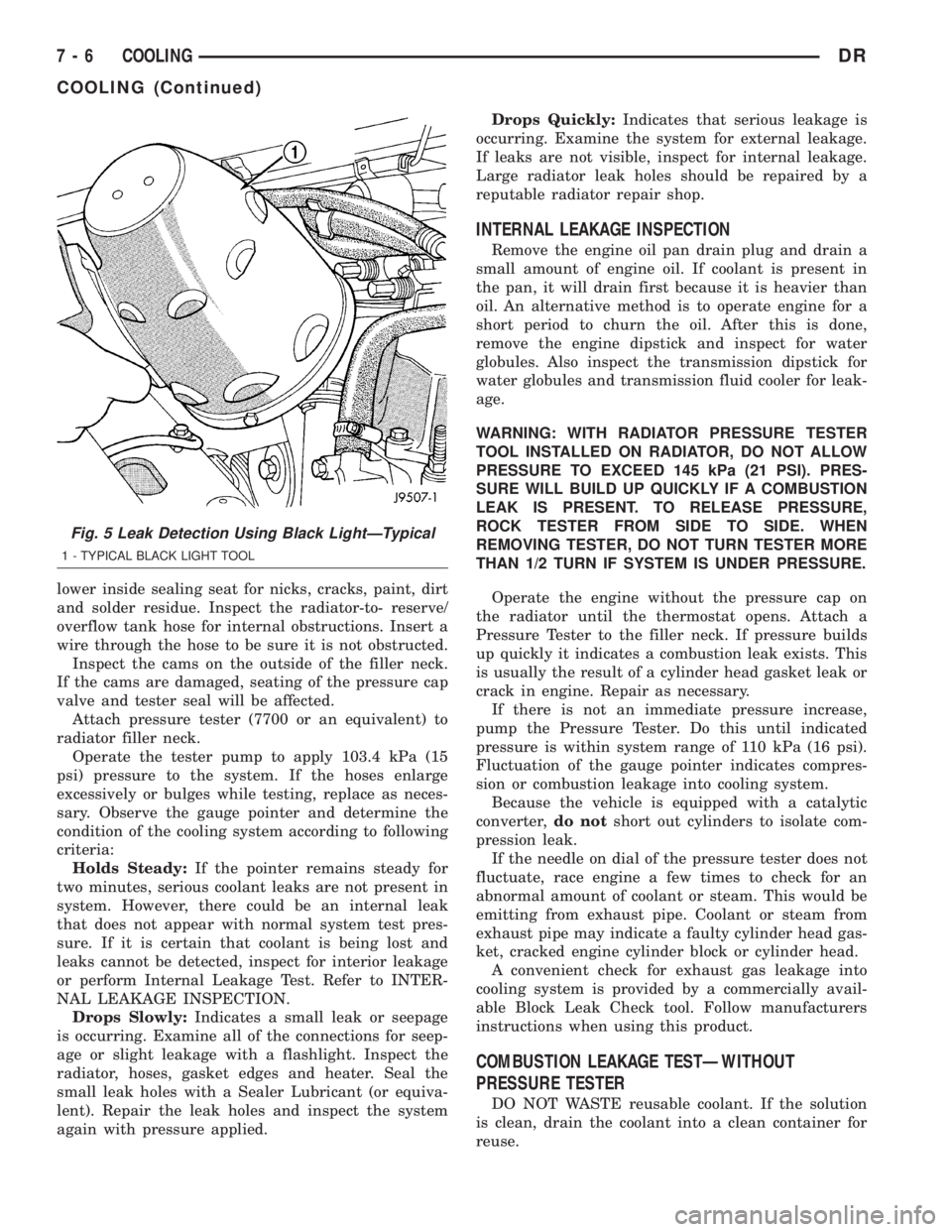
Fig. 5 Leak Detection Using Black LightÐTypical
1 - TYPICAL BLACK LIGHT TOOL
7 - 6 COOLINGDR
COOLING (Continued)
Page 295 of 2895
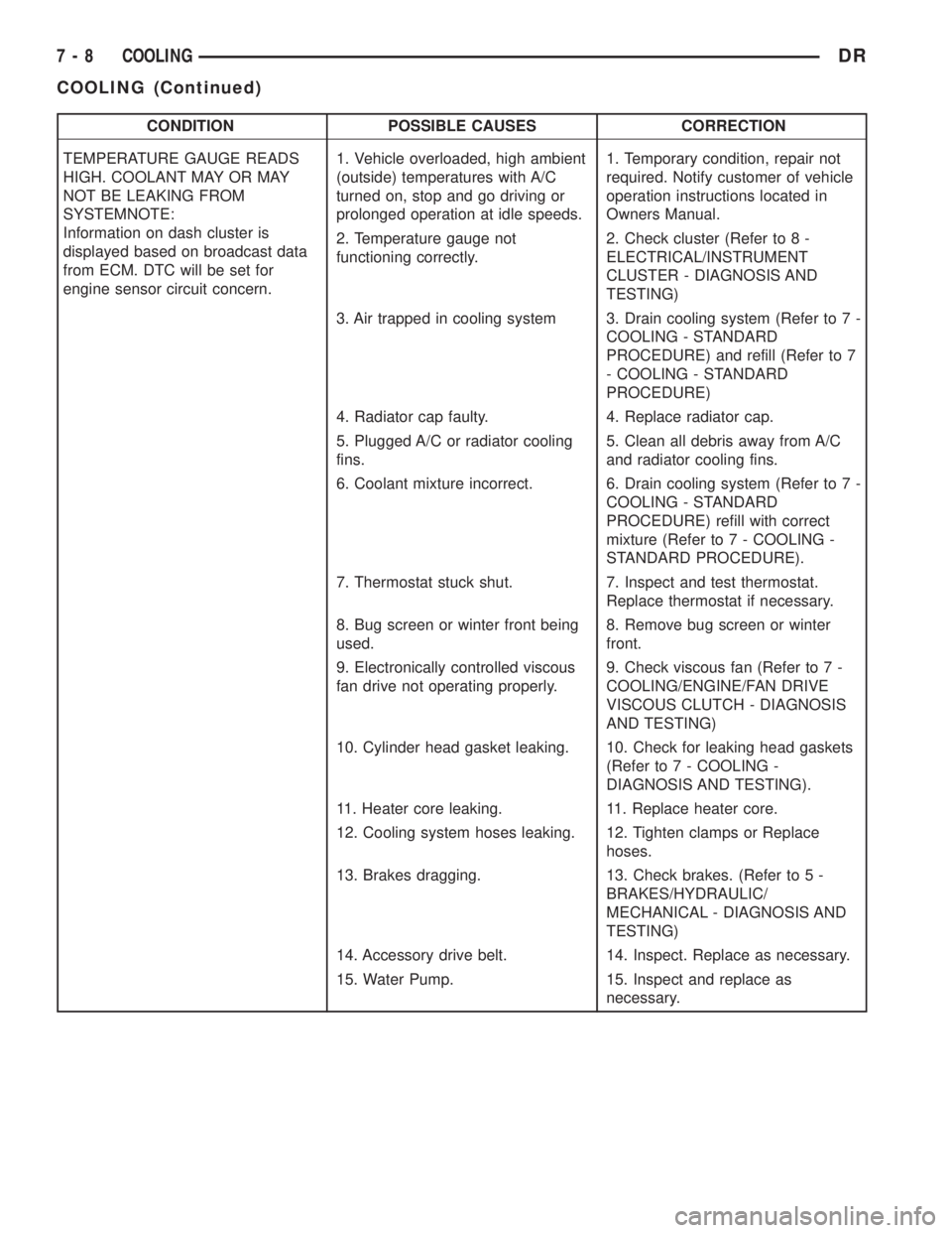
CONDITION POSSIBLE CAUSES CORRECTION
TEMPERATURE GAUGE READS
HIGH. COOLANT MAY OR MAY
NOT BE LEAKING FROM
SYSTEMNOTE:
Information on dash cluster is
displayed based on broadcast data
from ECM. DTC will be set for
engine sensor circuit concern.1. Vehicle overloaded, high ambient
(outside) temperatures with A/C
turned on, stop and go driving or
prolonged operation at idle speeds.1. Temporary condition, repair not
required. Notify customer of vehicle
operation instructions located in
Owners Manual.
2. Temperature gauge not
functioning correctly.2. Check cluster (Refer to 8 -
ELECTRICAL/INSTRUMENT
CLUSTER - DIAGNOSIS AND
TESTING)
3. Air trapped in cooling system 3. Drain cooling system (Refer to 7 -
COOLING - STANDARD
PROCEDURE) and refill (Refer to 7
- COOLING - STANDARD
PROCEDURE)
4. Radiator cap faulty. 4. Replace radiator cap.
5. Plugged A/C or radiator cooling
fins.5. Clean all debris away from A/C
and radiator cooling fins.
6. Coolant mixture incorrect. 6. Drain cooling system (Refer to 7 -
COOLING - STANDARD
PROCEDURE) refill with correct
mixture (Refer to 7 - COOLING -
STANDARD PROCEDURE).
7. Thermostat stuck shut. 7. Inspect and test thermostat.
Replace thermostat if necessary.
8. Bug screen or winter front being
used.8. Remove bug screen or winter
front.
9. Electronically controlled viscous
fan drive not operating properly.9. Check viscous fan (Refer to 7 -
COOLING/ENGINE/FAN DRIVE
VISCOUS CLUTCH - DIAGNOSIS
AND TESTING)
10. Cylinder head gasket leaking. 10. Check for leaking head gaskets
(Refer to 7 - COOLING -
DIAGNOSIS AND TESTING).
11. Heater core leaking. 11. Replace heater core.
12. Cooling system hoses leaking. 12. Tighten clamps or Replace
hoses.
13. Brakes dragging. 13. Check brakes. (Refer to 5 -
BRAKES/HYDRAULIC/
MECHANICAL - DIAGNOSIS AND
TESTING)
14. Accessory drive belt. 14. Inspect. Replace as necessary.
15. Water Pump. 15. Inspect and replace as
necessary.
7 - 8 COOLINGDR
COOLING (Continued)
Page 300 of 2895
CONDITION POSSIBLE CAUSES CORRECTION
10. Radiator or A/C condenser
fins are dirty or clogged.10. Remove insects and debris. (Refer to
7 - COOLING - STANDARD
PROCEDURE).
11. Radiator core is corroded or
plugged.11. Have radiator re-cored or replaced.
12. Fuel or ignition system
problems.12. Refer to 14 - Fuel System or 8 -
Electrical for diagnosis and testing
procedures.
13. Dragging brakes. 13. Check and correct as necessary.
(Refer to 5 - BRAKES - DIAGNOSIS AND
TESTING) for correct procedures.
14. Bug screen or cardboard is
being , reducing airflow.14. Remove bug screen or cardboard.
15. Thermostat partially or
completely shut.15. Check thermostat operation and
replace as necessary. (Refer to 7 -
COOLING/ENGINE/ENGINE COOLANT
THERMOSTAT - REMOVAL) .
16. Viscous fan drive not
operating properly.16. Check fan drive operation and replace
as necessary. (Refer to 7 - COOLING/
ENGINE/FAN DRIVE VISCOUS CLUTCH
- REMOVAL).
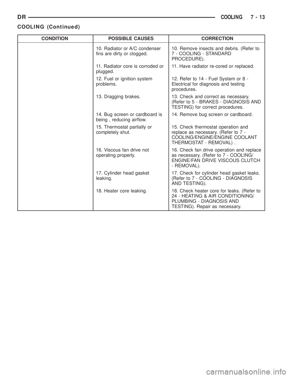
17. Cylinder head gasket
leaking.17. Check for cylinder head gasket leaks.
(Refer to 7 - COOLING - DIAGNOSIS
AND TESTING).
18. Heater core leaking. 18. Check heater core for leaks. (Refer to
24 - HEATING & AIR CONDITIONING/
PLUMBING - DIAGNOSIS AND
TESTING). Repair as necessary.
DRCOOLING 7 - 13
COOLING (Continued)
Page 301 of 2895
CONDITION POSSIBLE CAUSES CORRECTION
Temperature gauge reading is
inconsistent (flucttuates, cycles
or is erratic)1. During cold weather
operation, with the heater blower
in the high position, the gauge
reading may drop slightly.1. A normal condition. No correction
necessary.
2. Temperature gauge or engine
mounted gauge sensor defective
or shorted. Also, corroded or
loose wiring in this circuit.2. Check operation of gauge and repair if
necessary. (Refer to 8 - ELECTRICAL/
INSTRUMENT CLUSTER - DIAGNOSIS
AND TESTING).
3. Gauge reading rises when
vehicle is brought to a stop after
heavy use (engine still running)3. A normal condition. No correction is
necessary. Gauge should return to normal
range after vehicle is driven.
4. Gauge reading high after
re-starting a warmed up (hot)
engine.4. A normal condition. No correction is
necessary. The gauge should return to
normal range after a few minutes of
engine operation.
5. Coolant level low in radiator
(air will build up in the cooling
system causing the thermostat
to open late).5. Check and correct coolant leaks. (Refer
to 7 - COOLING - DIAGNOSIS AND
TESTING).
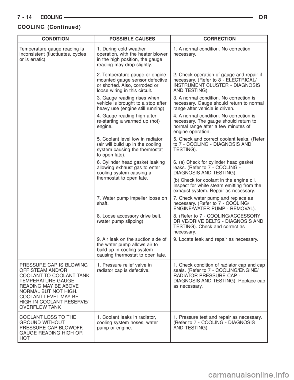
6. Cylinder head gasket leaking
allowing exhaust gas to enter
cooling system causing a
thermostat to open late.6. (a) Check for cylinder head gasket
leaks. (Refer to 7 - COOLING -
DIAGNOSIS AND TESTING).
(b) Check for coolant in the engine oil.
Inspect for white steam emitting from the
exhaust system. Repair as necessary.
7. Water pump impeller loose on
shaft.7. Check water pump and replace as
necessary. (Refer to 7 - COOLING/
ENGINE/WATER PUMP - REMOVAL).
8. Loose accessory drive belt.
(water pump slipping)8. (Refer to 7 - COOLING/ACCESSORY
DRIVE/DRIVE BELTS - DIAGNOSIS AND
TESTING). Check and correct as
necessary.
9. Air leak on the suction side of
the water pump allows air to
build up in cooling system
causing thermostat to open late.9. Locate leak and repair as necessary.
PRESSURE CAP IS BLOWING
OFF STEAM AND/OR
COOLANT TO COOLANT TANK.
TEMPERATURE GAUGE
READING MAY BE ABOVE
NORMAL BUT NOT HIGH.
COOLANT LEVEL MAY BE
HIGH IN COOLANT RESERVE/
OVERFLOW TANK1. Pressure relief valve in
radiator cap is defective.1. Check condition of radiator cap and cap
seals. (Refer to 7 - COOLING/ENGINE/
RADIATOR PRESSURE CAP -
DIAGNOSIS AND TESTING). Replace cap
as necessary.
COOLANT LOSS TO THE
GROUND WITHOUT
PRESSURE CAP BLOWOFF.
GAUGE READING HIGH OR
HOT1. Coolant leaks in radiator,
cooling system hoses, water
pump or engine.1. Pressure test and repair as necessary.
(Refer to 7 - COOLING - DIAGNOSIS
AND TESTING).
7 - 14 COOLINGDR
COOLING (Continued)
Page 339 of 2895
ENGINE COOLANT
THERMOSTAT - 5.9L DIESEL
DESCRIPTION
CAUTION: Do not operate an engine without a ther-
mostat, except for servicing or testing. An engine
with the thermostat removed will operate in the
radiator bypass mode, causing an overheat condi-
tion.
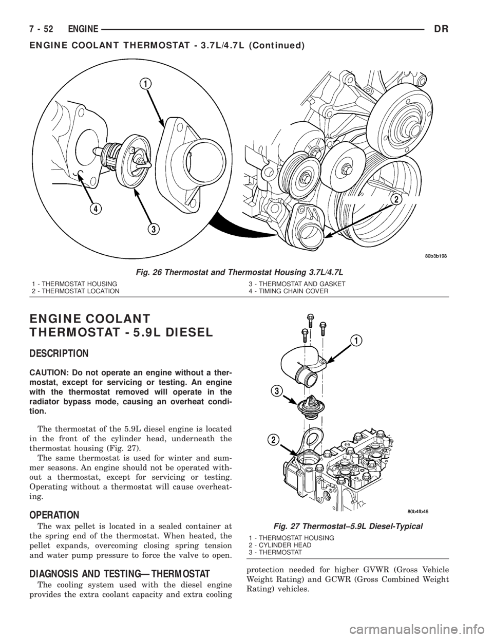
The thermostat of the 5.9L diesel engine is located
in the front of the cylinder head, underneath the
thermostat housing (Fig. 27).
The same thermostat is used for winter and sum-
mer seasons. An engine should not be operated with-
out a thermostat, except for servicing or testing.
Operating without a thermostat will cause overheat-
ing.
OPERATION
The wax pellet is located in a sealed container at
the spring end of the thermostat. When heated, the
pellet expands, overcoming closing spring tension
and water pump pressure to force the valve to open.
DIAGNOSIS AND TESTINGÐTHERMOSTAT
The cooling system used with the diesel engine
provides the extra coolant capacity and extra coolingprotection needed for higher GVWR (Gross Vehicle
Weight Rating) and GCWR (Gross Combined Weight
Rating) vehicles.
Fig. 26 Thermostat and Thermostat Housing 3.7L/4.7L
1 - THERMOSTAT HOUSING
2 - THERMOSTAT LOCATION3 - THERMOSTAT AND GASKET
4 - TIMING CHAIN COVER
Fig. 27 Thermostat±5.9L Diesel-Typical
1 - THERMOSTAT HOUSING
2 - CYLINDER HEAD
3 - THERMOSTAT
7 - 52 ENGINEDR
ENGINE COOLANT THERMOSTAT - 3.7L/4.7L (Continued)
Page 1250 of 2895
ENGINE
TABLE OF CONTENTS
page page
ENGINE - 3.7L............................ 1
ENGINE - 4.7L........................... 87
ENGINE - 5.7L.......................... 176ENGINE - 5.9L.......................... 223
ENGINE 5.9L DIESEL..................... 280
ENGINE 8.0L............................ 351
ENGINE - 3.7L
TABLE OF CONTENTS
page page
ENGINE - 3.7L
DESCRIPTION..........................3
DIAGNOSIS AND TESTING
DIAGNOSIS AND TESTING - ENGINE
DIAGNOSIS - INTRODUCTION............4
DIAGNOSIS AND TESTING - ENGINE
DIAGNOSIS - PERFORMANCE............4
DIAGNOSIS AND TESTING - ENGINE
DIAGNOSIS - MECHANICAL..............6
DIAGNOSIS AND TESTING - ENGINE
DIAGNOSIS - LUBRICATION..............7
DIAGNOSIS AND TESTING - CYLINDER
COMPRESSION PRESSURE..............8
DIAGNOSIS AND TESTING - CYLINDER
COMBUSTION PRESSURE LEAKAGE.......8
STANDARD PROCEDURE
STANDARD PROCEDURE - REPAIR
DAMAGED OR WORN THREADS..........9
STANDARD PROCEDURE - FORM-IN-
PLACE GASKETS AND SEALERS..........9
STANDARD PROCEDURE - ENGINE
GASKET SURFACE PREPARATION........10
REMOVAL.............................10
INSTALLATION.........................11
SPECIFICATIONS
SPECIFICATIONS ± 3.7L ENGINE.........12
TORQUE............................15
SPECIAL TOOLS.......................16
AIR CLEANER ELEMENT
REMOVAL.............................20
INSTALLATION.........................20
CYLINDER HEAD - LEFT
DIAGNOSIS AND TESTING - CYLINDER HEAD
GASKET............................20
REMOVAL.............................21
INSTALLATION.........................23CAMSHAFT(S)
DESCRIPTION.........................24
REMOVAL.............................24
INSTALLATION.........................25
CYLINDER HEAD COVER(S)
DESCRIPTION.........................26
REMOVAL.............................26
INSTALLATION.........................27
INTAKE/EXHAUST VALVES & SEATS
DESCRIPTION.........................27
STANDARD PROCEDURE - REFACING......27
REMOVAL.............................28
INSTALLATION.........................29
ROCKER ARM
DESCRIPTION.........................30
REMOVAL.............................30
INSTALLATION.........................30
VALVE GUIDE SEALS
DESCRIPTION.........................31
VALVE SPRINGS
DESCRIPTION.........................31
REMOVAL.............................31
INSTALLATION.........................31
CYLINDER HEAD - RIGHT
DIAGNOSIS AND TESTING - HYDRAULIC
LASH ADJUSTER.....................31
REMOVAL.............................32
INSTALLATION.........................32
CAMSHAFT(S)
DESCRIPTION.........................34
REMOVAL.............................34
INSTALLATION.........................35
CYLINDER HEAD COVER(S)
REMOVAL.............................35
INSTALLATION.........................36
DRENGINE 9 - 1
Page 1253 of 2895
DIAGNOSIS AND TESTING
DIAGNOSIS AND TESTING - ENGINE
DIAGNOSIS - INTRODUCTION
Engine diagnosis is helpful in determining the
causes of malfunctions not detected and remedied by
routine maintenance.
These malfunctions may be classified as either per-
formance (e.g., engine idles rough and stalls) or
mechanical (e.g., a strange noise).
(Refer to 9 - ENGINE - DIAGNOSIS AND TEST-
ING)ÐPERFORMANCE and (Refer to 9 - ENGINE -
DIAGNOSIS AND TESTING)ÐMECHANICAL for
possible causes and corrections of malfunctions.
(Refer to 14 - FUEL SYSTEM/FUEL DELIVERY -
DIAGNOSIS AND TESTING) and (Refer to 14 -
FUEL SYSTEM/FUEL INJECTION - DIAGNOSIS
AND TESTING) for the fuel system diagnosis.Additional tests and diagnostic procedures may be
necessary for specific engine malfunctions that can
not be isolated with the Service Diagnosis charts.
Information concerning additional tests and diagno-
sis is provided within the following diagnosis:
²Cylinder Compression Pressure Test (Refer to 9 -
ENGINE - DIAGNOSIS AND TESTING).
²Cylinder Combustion Pressure Leakage Test
(Refer to 9 - ENGINE - DIAGNOSIS AND TEST-
ING).
²Engine Cylinder Head Gasket Failure Diagnosis
(Refer to 9 - ENGINE/CYLINDER HEAD - DIAGNO-
SIS AND TESTING).
²Intake Manifold Leakage Diagnosis (Refer to 9 -
ENGINE/MANIFOLDS/INTAKE MANIFOLD -
DIAGNOSIS AND TESTING).
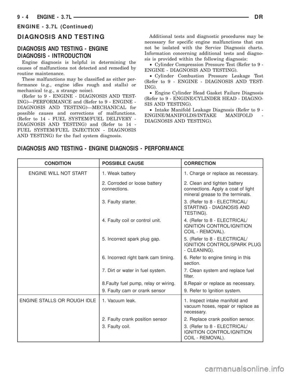
DIAGNOSIS AND TESTING - ENGINE DIAGNOSIS - PERFORMANCE
CONDITION POSSIBLE CAUSE CORRECTION
ENGINE WILL NOT START 1. Weak battery 1. Charge or replace as necessary.
2. Corroded or loose battery
connections.2. Clean and tighten battery
connections. Apply a coat of light
mineral grease to the terminals.
3. Faulty starter. 3. (Refer to 8 - ELECTRICAL/
STARTING - DIAGNOSIS AND
TESTING).
4. Faulty coil or control unit. 4. (Refer to 8 - ELECTRICAL/
IGNITION CONTROL/IGNITION
COIL - REMOVAL).
5. Incorrect spark plug gap. 5. (Refer to 8 - ELECTRICAL/
IGNITION CONTROL/SPARK PLUG
- CLEANING).
6. Incorrect right bank cam timing. 6. Refer to engine timing in this
section.
7. Dirt or water in fuel system. 7. Clean system and replace fuel
filter.
8.Faulty fuel pump, relay or wiring. 8.Repair or replace as necessary.
9. Faulty cam or crank sensor 9. Refer to Ignition system.
ENGINE STALLS OR ROUGH IDLE 1. Vacuum leak. 1. Inspect intake manifold and
vacuum hoses, repair or replace as
necessary.
2. Faulty crank position sensor 2. Replace crank position sensor.
3. Faulty coil. 3. (Refer to 8 - ELECTRICAL/
IGNITION CONTROL/IGNITION
COIL - REMOVAL).
9 - 4 ENGINE - 3.7LDR
ENGINE - 3.7L (Continued)
Page 1254 of 2895
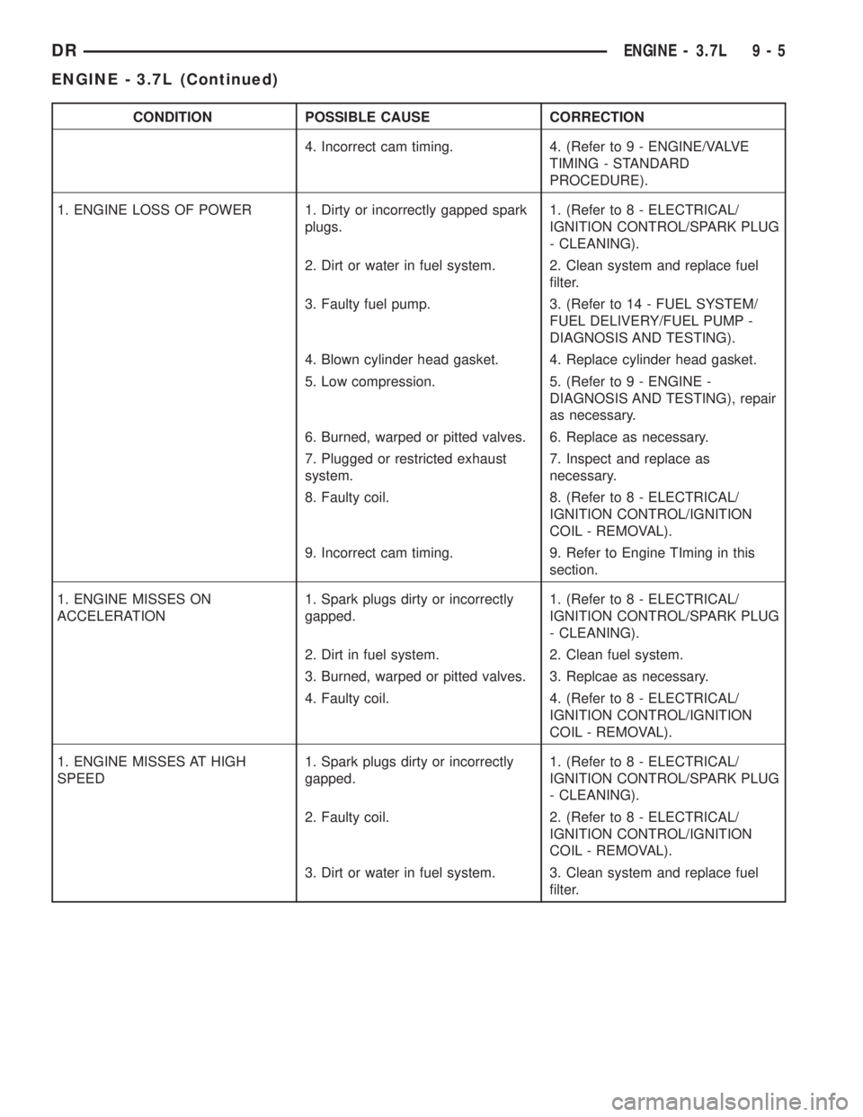
CONDITION POSSIBLE CAUSE CORRECTION
4. Incorrect cam timing. 4. (Refer to 9 - ENGINE/VALVE
TIMING - STANDARD
PROCEDURE).
1. ENGINE LOSS OF POWER 1. Dirty or incorrectly gapped spark
plugs.1. (Refer to 8 - ELECTRICAL/
IGNITION CONTROL/SPARK PLUG
- CLEANING).
2. Dirt or water in fuel system. 2. Clean system and replace fuel
filter.
3. Faulty fuel pump. 3. (Refer to 14 - FUEL SYSTEM/
FUEL DELIVERY/FUEL PUMP -
DIAGNOSIS AND TESTING).
4. Blown cylinder head gasket. 4. Replace cylinder head gasket.
5. Low compression. 5. (Refer to 9 - ENGINE -
DIAGNOSIS AND TESTING), repair
as necessary.
6. Burned, warped or pitted valves. 6. Replace as necessary.
7. Plugged or restricted exhaust
system.7. Inspect and replace as
necessary.
8. Faulty coil. 8. (Refer to 8 - ELECTRICAL/
IGNITION CONTROL/IGNITION
COIL - REMOVAL).
9. Incorrect cam timing. 9. Refer to Engine TIming in this
section.
1. ENGINE MISSES ON
ACCELERATION1. Spark plugs dirty or incorrectly
gapped.1. (Refer to 8 - ELECTRICAL/
IGNITION CONTROL/SPARK PLUG
- CLEANING).
2. Dirt in fuel system. 2. Clean fuel system.
3. Burned, warped or pitted valves. 3. Replcae as necessary.
4. Faulty coil. 4. (Refer to 8 - ELECTRICAL/
IGNITION CONTROL/IGNITION
COIL - REMOVAL).
1. ENGINE MISSES AT HIGH
SPEED1. Spark plugs dirty or incorrectly
gapped.1. (Refer to 8 - ELECTRICAL/
IGNITION CONTROL/SPARK PLUG
- CLEANING).
2. Faulty coil. 2. (Refer to 8 - ELECTRICAL/
IGNITION CONTROL/IGNITION
COIL - REMOVAL).
3. Dirt or water in fuel system. 3. Clean system and replace fuel
filter.
DRENGINE - 3.7L 9 - 5
ENGINE - 3.7L (Continued)
Page 1258 of 2895
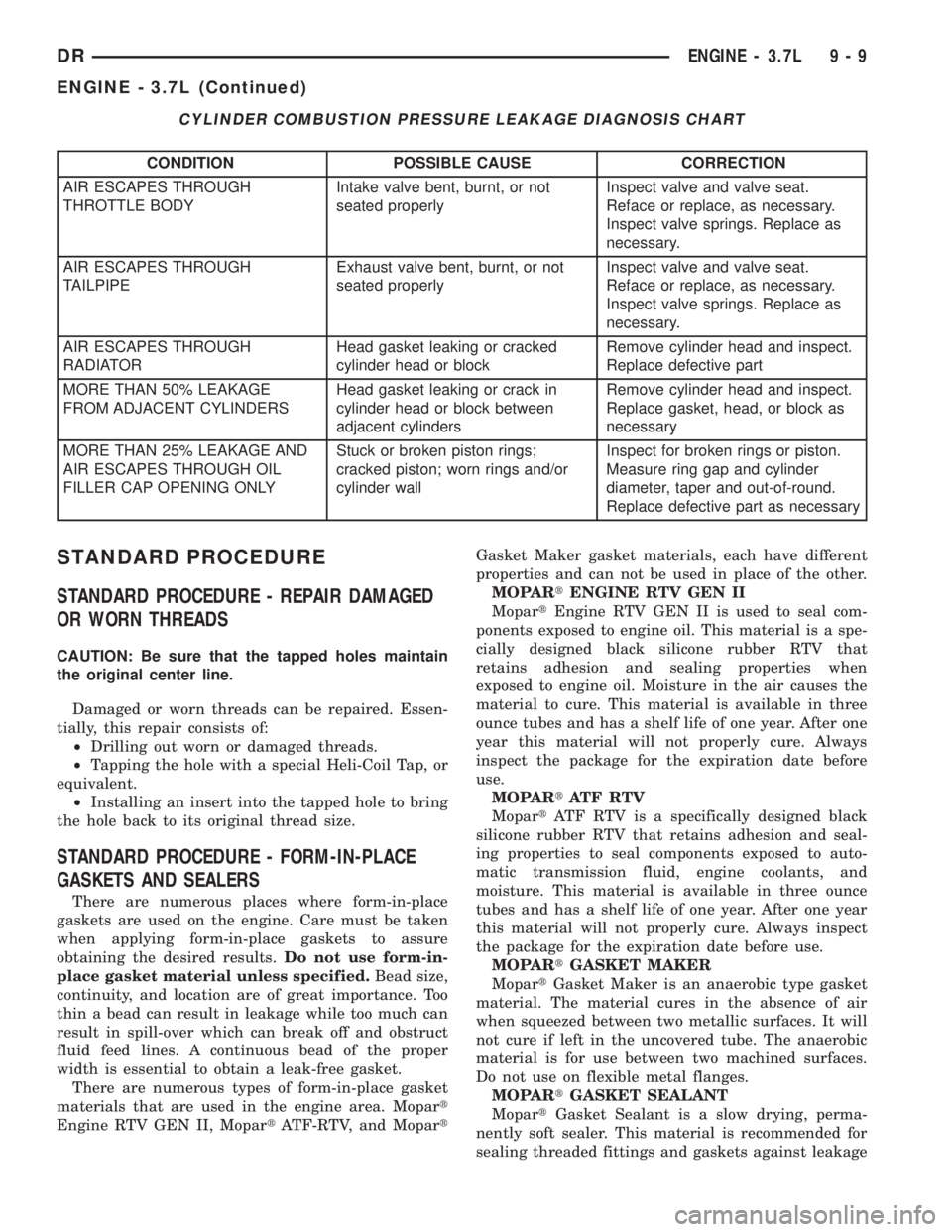
CYLINDER COMBUSTION PRESSURE LEAKAGE DIAGNOSIS CHART
CONDITION POSSIBLE CAUSE CORRECTION
AIR ESCAPES THROUGH
THROTTLE BODYIntake valve bent, burnt, or not
seated properlyInspect valve and valve seat.
Reface or replace, as necessary.
Inspect valve springs. Replace as
necessary.
AIR ESCAPES THROUGH
TAILPIPEExhaust valve bent, burnt, or not
seated properlyInspect valve and valve seat.
Reface or replace, as necessary.
Inspect valve springs. Replace as
necessary.
AIR ESCAPES THROUGH
RADIATORHead gasket leaking or cracked
cylinder head or blockRemove cylinder head and inspect.
Replace defective part
MORE THAN 50% LEAKAGE
FROM ADJACENT CYLINDERSHead gasket leaking or crack in
cylinder head or block between
adjacent cylindersRemove cylinder head and inspect.
Replace gasket, head, or block as
necessary
MORE THAN 25% LEAKAGE AND
AIR ESCAPES THROUGH OIL
FILLER CAP OPENING ONLYStuck or broken piston rings;
cracked piston; worn rings and/or
cylinder wallInspect for broken rings or piston.
Measure ring gap and cylinder
diameter, taper and out-of-round.
Replace defective part as necessary
STANDARD PROCEDURE
STANDARD PROCEDURE - REPAIR DAMAGED
OR WORN THREADS
CAUTION: Be sure that the tapped holes maintain
the original center line.
Damaged or worn threads can be repaired. Essen-
tially, this repair consists of:
²Drilling out worn or damaged threads.
²Tapping the hole with a special Heli-Coil Tap, or
equivalent.
²Installing an insert into the tapped hole to bring
the hole back to its original thread size.
STANDARD PROCEDURE - FORM-IN-PLACE
GASKETS AND SEALERS
There are numerous places where form-in-place
gaskets are used on the engine. Care must be taken
when applying form-in-place gaskets to assure
obtaining the desired results.Do not use form-in-
place gasket material unless specified.Bead size,
continuity, and location are of great importance. Too
thin a bead can result in leakage while too much can
result in spill-over which can break off and obstruct
fluid feed lines. A continuous bead of the proper
width is essential to obtain a leak-free gasket.
There are numerous types of form-in-place gasket
materials that are used in the engine area. Mopart
Engine RTV GEN II, MopartATF-RTV, and MopartGasket Maker gasket materials, each have different
properties and can not be used in place of the other.
MOPARtENGINE RTV GEN II
MopartEngine RTV GEN II is used to seal com-
ponents exposed to engine oil. This material is a spe-
cially designed black silicone rubber RTV that
retains adhesion and sealing properties when
exposed to engine oil. Moisture in the air causes the
material to cure. This material is available in three
ounce tubes and has a shelf life of one year. After one
year this material will not properly cure. Always
inspect the package for the expiration date before
use.
MOPARtATF RTV
MopartATF RTV is a specifically designed black
silicone rubber RTV that retains adhesion and seal-
ing properties to seal components exposed to auto-
matic transmission fluid, engine coolants, and
moisture. This material is available in three ounce
tubes and has a shelf life of one year. After one year
this material will not properly cure. Always inspect
the package for the expiration date before use.
MOPARtGASKET MAKER
MopartGasket Maker is an anaerobic type gasket
material. The material cures in the absence of air
when squeezed between two metallic surfaces. It will
not cure if left in the uncovered tube. The anaerobic
material is for use between two machined surfaces.
Do not use on flexible metal flanges.
MOPARtGASKET SEALANT
MopartGasket Sealant is a slow drying, perma-
nently soft sealer. This material is recommended for
sealing threaded fittings and gaskets against leakage
DRENGINE - 3.7L 9 - 9
ENGINE - 3.7L (Continued)
Page 1259 of 2895
of oil and coolant. Can be used on threaded and
machined parts under all temperatures. This mate-
rial is used on engines with multi-layer steel (MLS)
cylinder head gaskets. This material also will pre-
vent corrosion. MopartGasket Sealant is available in
a 13 oz. aerosol can or 4oz./16 oz. can w/applicator.
FORM-IN-PLACE GASKET AND SEALER
APPLICATION
Assembling parts using a form-in-place gasket
requires care but it's easier than using precut gas-
kets.
MopartGasket Maker material should be applied
sparingly 1 mm (0.040 in.) diameter or less of sealant
to one gasket surface. Be certain the material sur-
rounds each mounting hole. Excess material can eas-
ily be wiped off. Components should be torqued in
place within 15 minutes. The use of a locating dowel
is recommended during assembly to prevent smear-
ing material off the location.
MopartEngine RTV GEN II or ATF RTV gasket
material should be applied in a continuous bead
approximately 3 mm (0.120 in.) in diameter. All
mounting holes must be circled. For corner sealing, a
3.17 or 6.35 mm (1/8 or 1/4 in.) drop is placed in the
center of the gasket contact area. Uncured sealant
may be removed with a shop towel. Components
should be torqued in place while the sealant is still
wet to the touch (within 10 minutes). The usage of a
locating dowel is recommended during assembly to
prevent smearing material off the location.
MopartGasket Sealant in an aerosol can should be
applied using a thin, even coat sprayed completely
over both surfaces to be joined, and both sides of a
gasket. Then proceed with assembly. Material in a
can w/applicator can be brushed on evenly over the
sealing surfaces. Material in an aerosol can should be
used on engines with multi-layer steel gaskets.
STANDARD PROCEDURE - ENGINE GASKET
SURFACE PREPARATION
To ensure engine gasket sealing, proper surface
preparation must be performed, especially with the
use of aluminum engine components and multi-layer
steel cylinder head gaskets.
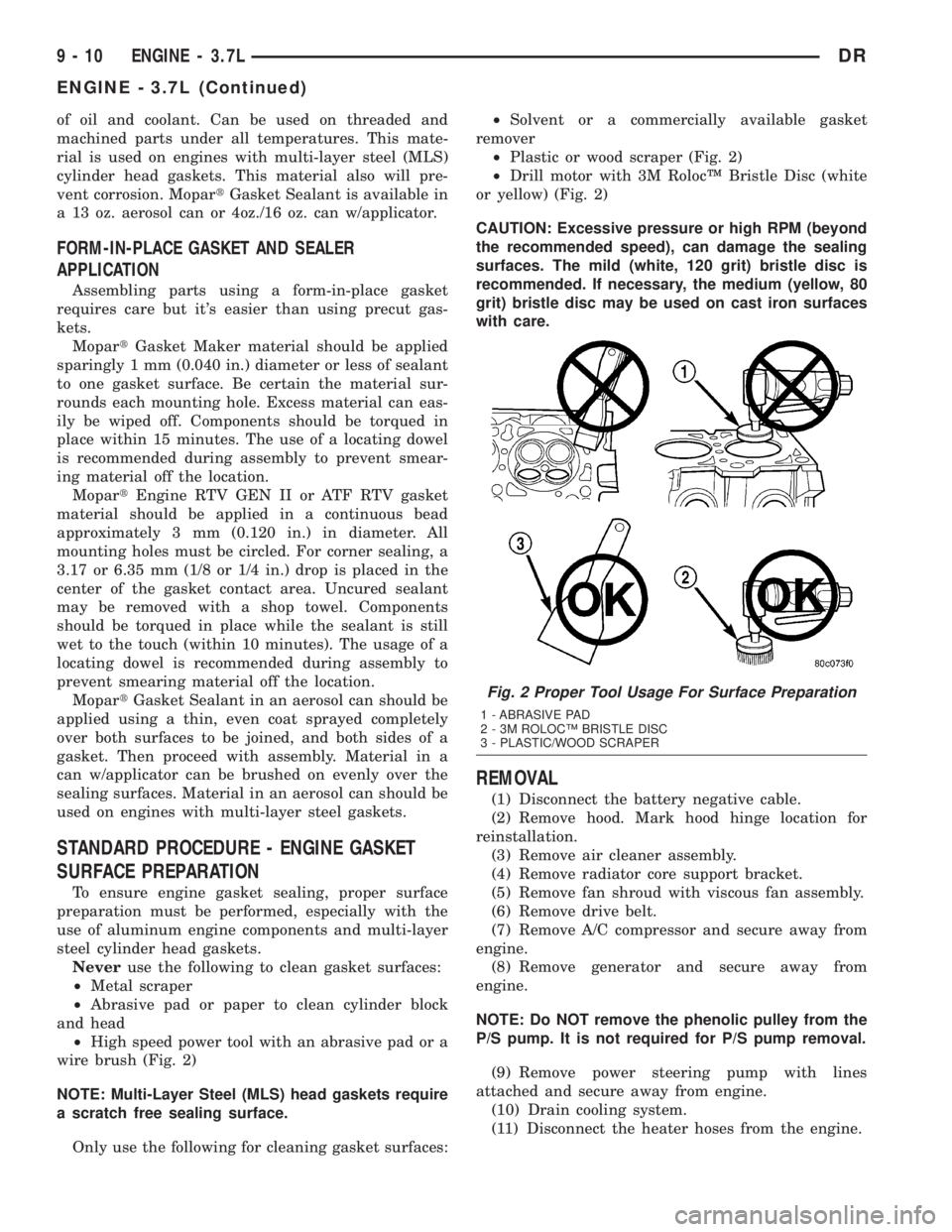
Neveruse the following to clean gasket surfaces:
²Metal scraper
²Abrasive pad or paper to clean cylinder block
and head
²High speed power tool with an abrasive pad or a
wire brush (Fig. 2)
NOTE: Multi-Layer Steel (MLS) head gaskets require
a scratch free sealing surface.
Only use the following for cleaning gasket surfaces:²Solvent or a commercially available gasket
remover
²Plastic or wood scraper (Fig. 2)
²Drill motor with 3M RolocŸ Bristle Disc (white
or yellow) (Fig. 2)
CAUTION: Excessive pressure or high RPM (beyond
the recommended speed), can damage the sealing
surfaces. The mild (white, 120 grit) bristle disc is
recommended. If necessary, the medium (yellow, 80
grit) bristle disc may be used on cast iron surfaces
with care.
REMOVAL
(1) Disconnect the battery negative cable.
(2) Remove hood. Mark hood hinge location for
reinstallation.
(3) Remove air cleaner assembly.
(4) Remove radiator core support bracket.
(5) Remove fan shroud with viscous fan assembly.
(6) Remove drive belt.
(7) Remove A/C compressor and secure away from
engine.
(8) Remove generator and secure away from
engine.
NOTE: Do NOT remove the phenolic pulley from the
P/S pump. It is not required for P/S pump removal.
(9) Remove power steering pump with lines
attached and secure away from engine.
(10) Drain cooling system.
(11) Disconnect the heater hoses from the engine.
Fig. 2 Proper Tool Usage For Surface Preparation
1 - ABRASIVE PAD
2 - 3M ROLOCŸ BRISTLE DISC
3 - PLASTIC/WOOD SCRAPER
9 - 10 ENGINE - 3.7LDR
ENGINE - 3.7L (Continued)