fold seats DODGE RAM 2003 Service Repair Manual
[x] Cancel search | Manufacturer: DODGE, Model Year: 2003, Model line: RAM, Model: DODGE RAM 2003Pages: 2895, PDF Size: 83.15 MB
Page 451 of 2895
the element grids to the heated seat module through
the seat wire harness.
One temperature sensor is used for each front seat,
and it is located in the center insert area of the seat
cushion element. The heated seat sensors and their
pigtail wires are also captured between a covering
and the adhesive foam rubber backing. The heated
seat sensors are Negative Thermal Coefficient (NTC)
thermistors. The sensors for both front seats receive
a voltage feed from a single output of the heated seat
module, but the module receives individual sensor
inputs from the driver side and passenger side sen-
sors.
The heated seat elements and sensors should not
be repaired. If damaged or faulty, the heated seat ele-
ment assembly must be replaced.
OPERATION
One end of the heated seat element resistor wire is
connected to ground at all times through a splice in
the heated seat module ground circuit. Battery cur-
rent is directed to the other end of the heated seat
element resistor wire by the energized N-channel
Field Effect Transistor (N-FET) located within the
heated seat module. The heated seat module will
energize the N-FET only when the heated seat
switch is in the Low or High position and the heated
seat sensor indicates that the seat cushion surface
temperature is below the selected (Low or High) tem-
perature set point. As electrical current passes
through the heating element grid, the resistance of
the wire used in the element disperses some of that
electrical current in the form of heat. The heat pro-
duced by the heated seat element grid then radiates
through the seat trim cover, warming its occupant.
The resistance of the heated seat sensor increases
and decreases as the surface temperature of the seat
cushion cover changes. The heated seat module sup-
plies each sensor with a 5v voltage feed, then uses
the sensor resistance to determine when the heated
seat element grids need to be cycled on or off in order
to maintain the selected temperature set point.
DIAGNOSIS AND TESTING - HEATED SEAT
ELEMENT
The heated seat module will self-diagnose shorted
or open heated seat element circuits and sensor cir-
cuits. Refer to Heated Seat System Diagnosis and
Testing in this section for additional diagnosis and
testing procedures. To manually check the heated
seat element, proceed as follows. The wire harness
connectors for the seat cushion and seat back heating
elements and sensor are located on the right side of
the seat, near the edge of the seat cushion frame.
The proper connector can be identified by the foam
wrapping.NOTE: When checking heated seat elements for
continuity, be certain to move the heating element
being checked. Moving the element, such as sitting
in the seat will eliminate the possibility of an inter-
mittent open in the element which would only be
evident if the element was in a certain position.
Failure to check the element in various positions
could result in an incomplete test.
(1) Position the appropriate seat in the full for-
ward position.
(2) Make certain the ignition switch is in the OFF
position.
(3) Disconnect the heated seat element connector
which requires testing. Check for continuity between
the two heated seat element circuit cavities while
moving the appropriate seat cushion. Refer toWir-
ingfor the location of complete heated seat system
wiring diagrams. There should be continuity. If OK,
the elements within the seat assembly test OK, go to
Step 4. If not OK, replace the faulty seat heating ele-
ment, refer to the procedure in this section.
(4) Test the seat wire harness between the heated
seat module connector and the appropriate heated
seat wire harness connector for shorted or open cir-
cuits. If OK, element is OK, proceed with testing the
heated seat sensor and module. If not OK, repair the
shorted or open seat wire harness as required.
REMOVAL
Do not remove the heating element from the seat
or seat back cushion. The original element is perma-
nently attached to the seat cushions and cannot be
removed without damaging the cushion. The replace-
ment heating element is designed to be applied
directly over the original seat heating element.
(1) Disconnect and isolate the negative battery
cable.
(2) Remove the appropriate seat cushion or seat
back trim cover. Refer to the Body section of this
manual for the procedures.
(3) Disconnect the inoperative heated seat cushion
or seat back element electrical connectors.
(4) Locate the wires leading from the inoperative
heating element and cut them off flush with the edge
of the original heating element.
INSTALLATION
(1) Peel off the adhesive backing on the back of the
replacement heating element and stick directly over
the original heating element (Fig. 3).
CAUTION: During the installation of the replace-
ment heating element, be careful not to fold or
crease the element assembly. Folds or creases will
cause premature failure.
8G - 6 HEATED SEAT SYSTEMDR
HEATED SEAT ELEMENT (Continued)
Page 1444 of 2895
þ Loss of engine power
þ Engine misfiring
þ Poor fuel economy
²Possible indications of the cylinder head gasket
leaking between a cylinder and an adjacent water
jacket are:
þ Engine overheating
þ Loss of coolant
þ Excessive steam (white smoke) emitting from
exhaust
þ Coolant foaming
CYLINDER-TO-CYLINDER LEAKAGE TEST
To determine if an engine cylinder head gasket is
leaking between adjacent cylinders, follow the proce-
dures in Cylinder Compression Pressure Test in this
section. An engine cylinder head gasket leaking
between adjacent cylinders will result in approxi-
mately a 50±70% reduction in compression pressure.
CYLINDER-TO-WATER JACKET LEAKAGE TEST
WARNING: USE EXTREME CAUTION WHEN THE
ENGINE IS OPERATING WITH COOLANT PRES-
SURE CAP REMOVED.
VISUAL TEST METHOD
With the engine cool, remove the coolant pressure
cap. Start the engine and allow it to warm up until
thermostat opens.
If a large combustion/compression pressure leak
exists, bubbles will be visible in the coolant.
COOLING SYSTEM TESTER METHOD
WARNING: WITH COOLING SYSTEM TESTER IN
PLACE, PRESSURE WILL BUILD UP FAST. EXCES-
SIVE PRESSURE BUILT UP, BY CONTINUOUS
ENGINE OPERATION, MUST BE RELEASED TO A
SAFE PRESSURE POINT. NEVER PERMIT PRES-
SURE TO EXCEED 138 kPa (20 psi).
Install Cooling System Tester 7700 or equivalent to
pressure cap neck. Start the engine and observe the
tester's pressure gauge. If gauge pulsates with every
power stroke of a cylinder a combustion pressure
leak is evident.
CHEMICAL TEST METHOD
Combustion leaks into the cooling system can also
be checked by using Bloc-Chek Kit C-3685-A or
equivalent. Perform test following the procedures
supplied with the tool kit.
REMOVAL
(1) Disconnect the battery negative cable.
(2) Drain cooling system.
(3) Remove the air cleaner resonator and duct
work.
(4) Remove the generator.
(5) Remove closed crankcase ventilation system.
(6) Disconnect the evaporation control system.
(7) Perform the Fuel System Pressure Release pro-
cedure (Refer to 14 - FUEL SYSTEM/FUEL DELIV-
ERY - STANDARD PROCEDURE). Disconnect the
fuel supply line (Refer to 14 - FUEL SYSTEM/FUEL
DELIVERY/QUICK CONNECT FITTING - STAN-
DARD PROCEDURE).
(8) Disconnect heater hoses.
(9) Remove cylinder head covers and gaskets.
(10) Remove intake manifold and throttle body as
an assembly.
(11) Remove rocker arm assemblies and push rods.
Identify to ensure installation in original locations.
(12) Remove the head bolts from each cylinder
head and remove cylinder heads. Discard the cylin-
der head gasket.
CLEANING
Clean all surfaces of cylinder block and cylinder
heads.
Clean cylinder block front and rear gasket surfaces
using a suitable solvent.
INSPECTION
(1) Inspect the cylinder head for out-of-flatness,
using a straightedge and a feeler gauge. If tolerances
exceed 0.0508 mm (0.002 in.) replace the cylinder
head.
(2) Inspect the valve seats for damage. Service the
valve seats as necessary.
(3) Inspect the valve guides for wear, cracks or
looseness. If either condition exist, replace the cylin-
der head.
(4) Inspect pushrods. Replace worn or bent push-
rods.
INSTALLATION
(1) Clean all surfaces of cylinder block and cylin-
der heads.
(2) Clean cylinder block front and rear gasket sur-
faces using a suitable solvent.
CAUTION: The head gaskets are not interchange-
able between left and right sides. They are marked
ªLº and ªRº to indicate left and right sides.
(3) Position new cylinder head gaskets onto the
cylinder block.
DRENGINE - 5.7L 9 - 195
CYLINDER HEAD (Continued)
Page 1536 of 2895
EXCESSIVE WHITE SMOKE
POSSIBLE CAUSE CORRECTION
Fuel injector protrusion not correct. Check washer (shim) at bottom of fuel injector for
correct thickness. (Refer to 14 - FUEL SYSTEM/FUEL
INJECTION/FUEL INJECTOR - INSTALLATION)
Fuel injection pump malfunctioning. A DTC should have been set. Refer to Powertrain
Diagnostic Procedures Information.
Fuel supply side restriction to transfer pump. Refer to Powertrain Diagnostic Manual for fuel system
testing.
Fuel transfer (lift) pump malfunctioning. A DTC may have been set. Refer to Powertrain
Diagnostic Procedures Information.
Intake/Exhaust valve adjustments not correct (too tight). (Refer to 9 - ENGINE/CYLINDER HEAD/INTAKE/
EXHAUST VALVES & SEATS - STANDARD
PROCEDURE).
Intake manifold air temperature sensor malfunctioning. A DTC should have been set. Refer to Powertrain
Diagnostic Procedures Information.
Intake manifold heater circuit not functioning correctly in
cold weather.A DTC should have been set. Refer to Powertrain
Diagnostic Procedures Information. Also check heater
elements for correct operation.
Intake manifold heater elements not functioning
correctly in cold weather.A DTC should have been set if heater elements are
malfunctioning. Refer to Powertrain Diagnostic
Procedures Information.
Internal engine damage (scuffed cylinder). Analyze engine oil and inspect oil filter to locate area of
probable damage.
Restriction in fuel supply side of fuel system. Refer to Powertrain Diagnostic Manual for fuel system
testing.
EXCESSIVE BLUE SMOKE
POSSIBLE CAUSE CORRECTION
Dirty air cleaner or restricted turbocharger intake duct. Check Filter MinderTat air filter housing. (Refer to 9 -
ENGINE/AIR INTAKE SYSTEM/AIR CLEANER
ELEMENT - REMOVAL).
Air leak in boost system between turbocharger
compressor outlet and intake manifold.Service air charge system..
Obstruction in exhaust manifold. Remove exhaust manifold and inspect for blockage
(Refer to 9 - ENGINE/MANIFOLDS/EXHAUST
MANIFOLD - REMOVAL).
Restricted turbocharger drain tube. Remove turbocharger drain tube and remove
obstruction.
Crankcase ventilation system plugged. Inspect crankcase ventilation system for function
Valve seals are worn, brittle, or improperly installed. Replace valve stem oil seals (Refer to 9 - ENGINE/
CYLINDER HEAD/INTAKE/EXHAUST VALVES &
SEATS - REMOVAL).
Valve stems and/or guides are worn. Remove valves and inspect valves and guides. (Refer
to 9 - ENGINE/CYLINDER HEAD/INTAKE/EXHAUST
VALVES & SEATS - STANDARD PROCEDURE).
Broken or Improperly installed piston rings. Tear down engine and inspect piston rings.
DRENGINE 5.9L DIESEL 9 - 287
ENGINE 5.9L DIESEL (Continued)
Page 1556 of 2895
Measure valve margin (rim thickness) (Fig. 28).
Measure the valve spring free length and maxi-
mum inclination (Fig. 29).
Test valve spring force with tool C-647 (Fig. 30).
Specification 72.0 Ð 80.7 lbs. when compressed to
35.33 mm (1.39 in.).
INSTALLATION
(1) Install new valve seals. The yellow seals are for
the intake valves and the green seals are for the
exhaust valves.
(2) Install the valves in their original postion. The
exhaust valves are identified by a dimple on the
valve head (Fig. 31).
(3) Install the valve springs and retainer.
(4) Install the valve spring compressor tool 8319±A
as shown in (Fig. 22) and (Fig. 23).(5) Compress the valve springs and install the
valve retaining locks (Fig. 24).
(6) Remove the compressor and repeat the proce-
dure on the remaining cylinders.
(7) Install new o-ring and sealing washer on injec-
tor.
(8) Lubricate o-ring and injector bore.
(9) Verify sealing washer (shim) was removed with
old injector.
(10) Install injector with fuel injector connector
port facing intake manifold.
(11) Install hold-down bolt. Torque to 10 Nm (89
in. lbs.).
(12) Install fuel injector connector and connector
nut. Torque nut to 50 Nm (36.8 ft. lbs.).
(13) Install the cylinder head (Refer to 9 -
ENGINE/CYLINDER HEAD - INSTALLATION).
Fig. 28 Measure Valve Margin (Rim Thickness)
VALVE MARGIN (RIM THICKNESS)
0.79 mm (0.031 in.) MIN.
Fig. 29 Measure Valve Spring Free Length and Max.
Inclination
APPROXIMATE VALVE SPRING FREE LENGTH
47.75 mm (1.88 in.)
MAX INCLINATION
1.5 mm (.059 in.)
Fig. 30 Testing Valve Spring with Tool C-647
1 - SPECIAL TOOL C-647
Fig. 31 Valve Identification
1 - INTAKE VALVES
2 - EXHAUST VALVES
DRENGINE 5.9L DIESEL 9 - 307
INTAKE/EXHAUST VALVES & SEATS (Continued)
Page 1594 of 2895
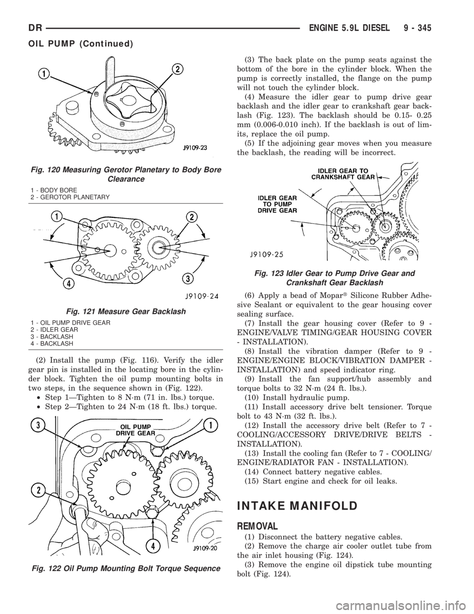
(2) Install the pump (Fig. 116). Verify the idler
gear pin is installed in the locating bore in the cylin-
der block. Tighten the oil pump mounting bolts in
two steps, in the sequence shown in (Fig. 122).
²Step 1ÐTighten to 8 N´m (71 in. lbs.) torque.
²Step 2ÐTighten to 24 N´m (18 ft. lbs.) torque.(3) The back plate on the pump seats against the
bottom of the bore in the cylinder block. When the
pump is correctly installed, the flange on the pump
will not touch the cylinder block.
(4) Measure the idler gear to pump drive gear
backlash and the idler gear to crankshaft gear back-
lash (Fig. 123). The backlash should be 0.15- 0.25
mm (0.006-0.010 inch). If the backlash is out of lim-
its, replace the oil pump.
(5) If the adjoining gear moves when you measure
the backlash, the reading will be incorrect.
(6) Apply a bead of MopartSilicone Rubber Adhe-
sive Sealant or equivalent to the gear housing cover
sealing surface.
(7) Install the gear housing cover (Refer to 9 -
ENGINE/VALVE TIMING/GEAR HOUSING COVER
- INSTALLATION).
(8) Install the vibration damper (Refer to 9 -
ENGINE/ENGINE BLOCK/VIBRATION DAMPER -
INSTALLATION) and speed indicator ring.
(9) Install the fan support/hub assembly and
torque bolts to 32 N´m (24 ft. lbs.).
(10) Install hydraulic pump.
(11) Install accessory drive belt tensioner. Torque
bolt to 43 N´m (32 ft. lbs.).
(12) Install the accessory drive belt (Refer to 7 -
COOLING/ACCESSORY DRIVE/DRIVE BELTS -
INSTALLATION).
(13) Install the cooling fan (Refer to 7 - COOLING/
ENGINE/RADIATOR FAN - INSTALLATION).
(14) Connect battery negative cables.
(15) Start engine and check for oil leaks.
INTAKE MANIFOLD
REMOVAL
(1) Disconnect the battery negative cables.
(2) Remove the charge air cooler outlet tube from
the air inlet housing (Fig. 124).
(3) Remove the engine oil dipstick tube mounting
bolt (Fig. 124).
Fig. 120 Measuring Gerotor Planetary to Body Bore
Clearance
1 - BODY BORE
2 - GEROTOR PLANETARY
Fig. 121 Measure Gear Backlash
1 - OIL PUMP DRIVE GEAR
2 - IDLER GEAR
3 - BACKLASH
4 - BACKLASH
Fig. 122 Oil Pump Mounting Bolt Torque Sequence
Fig. 123 Idler Gear to Pump Drive Gear and
Crankshaft Gear Backlash
DRENGINE 5.9L DIESEL 9 - 345
OIL PUMP (Continued)
Page 2651 of 2895
SEATS
TABLE OF CONTENTS
page page
CENTER SEAT
REMOVAL.............................76
INSTALLATION.........................77
CENTER ARMREST / SEAT BACK
REMOVAL.............................77
INSTALLATION.........................78
CENTER SEAT BACK INERTIA HINGE COVER
REMOVAL.............................78
INSTALLATION.........................78
CENTER SEAT BACK HINGE
REMOVAL.............................79
INSTALLATION.........................80
CENTER SEAT BACK LID
REMOVAL.............................80
INSTALLATION.........................80
CENTER SEAT CUSHION
REMOVAL.............................80
INSTALLATION.........................80
CENTER SEAT CUSHION COVER
REMOVAL.............................81
INSTALLATION.........................81
UNDER SEAT STORAGE BIN
REMOVAL.............................81
INSTALLATION.........................81
UNDER SEAT STORAGE BIN COVERING
REMOVAL.............................81
INSTALLATION.........................81
UNDER SEAT STORAGE BIN LATCH
REMOVAL.............................81
INSTALLATION.........................81
HEADREST
REMOVAL.............................82
INSTALLATION.........................82
HEADREST SLEEVE
REMOVAL.............................82INSTALLATION.........................82
SEAT - FRONT
REMOVAL.............................82
INSTALLATION.........................82
SEAT BACK CUSHION / COVER - FRONT
REMOVAL.............................83
INSTALLATION.........................83
SEAT CUSHION / COVER - FRONT
REMOVAL.............................83
INSTALLATION.........................83
SEAT TRACK
REMOVAL.............................83
INSTALLATION.........................83
SEAT - REAR
REMOVAL.............................84
INSTALLATION.........................84
SEAT BACK - REAR
REMOVAL.............................84
INSTALLATION.........................84
SEAT BACK CUSHION / COVER - REAR
REMOVAL.............................85
INSTALLATION.........................85
SEAT CUSHION / COVER - REAR
REMOVAL.............................85
INSTALLATION.........................85
SEAT CUSHION FRAME - REAR
REMOVAL.............................85
INSTALLATION.........................85
SEAT BACK REAR - FOOTMANS LOOP
BRACKETS
REMOVAL.............................85
INSTALLATION.........................85
CENTER SEAT
REMOVAL
NOTE: Do not reuse the seat fasteners, always
replace with new ones.
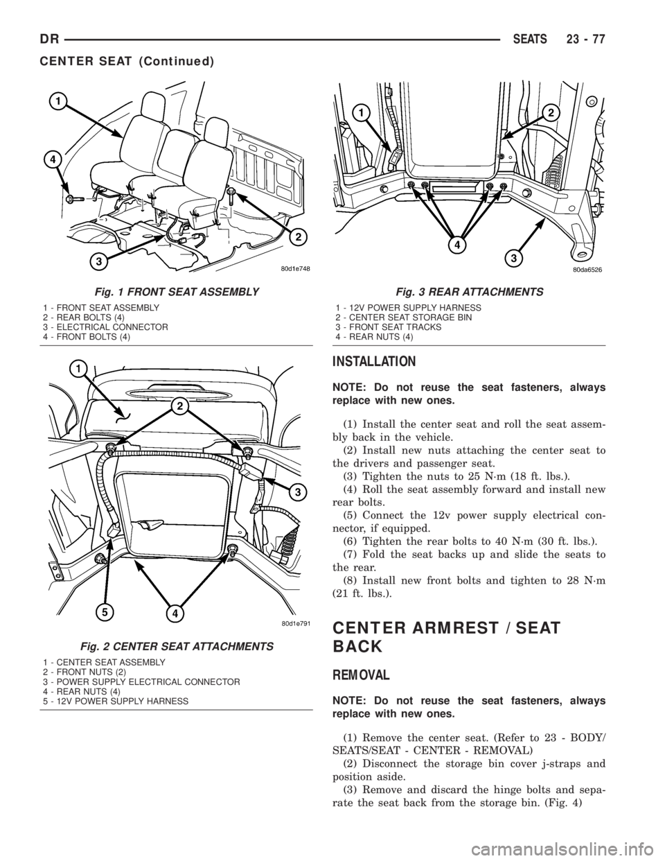
(1) Remove and discard the front bolts. (Fig. 1)
(2) Position the seats forward, remove the rear
bolts and discard.
(3) Disconnect the 12v power supply electrical con-
nector, if equipped. (Fig. 2)(4) Fold the seat backs forward and roll the seat
assembly back in the vehicle.
(5) Remove the nuts attaching the center seat to
the drivers seat and the passenger seat and discard.
(Fig. 3)
(6) Roll the seat assembly forward and remove the
center seat portion.
23 - 76 SEATSDR
Page 2652 of 2895
INSTALLATION
NOTE: Do not reuse the seat fasteners, always
replace with new ones.
(1) Install the center seat and roll the seat assem-
bly back in the vehicle.
(2) Install new nuts attaching the center seat to
the drivers and passenger seat.
(3) Tighten the nuts to 25 N´m (18 ft. lbs.).
(4) Roll the seat assembly forward and install new
rear bolts.
(5) Connect the 12v power supply electrical con-
nector, if equipped.
(6) Tighten the rear bolts to 40 N´m (30 ft. lbs.).
(7) Fold the seat backs up and slide the seats to
the rear.
(8) Install new front bolts and tighten to 28 N´m
(21 ft. lbs.).
CENTER ARMREST / SEAT
BACK
REMOVAL
NOTE: Do not reuse the seat fasteners, always
replace with new ones.
(1) Remove the center seat. (Refer to 23 - BODY/
SEATS/SEAT - CENTER - REMOVAL)
(2) Disconnect the storage bin cover j-straps and
position aside.
(3) Remove and discard the hinge bolts and sepa-
rate the seat back from the storage bin. (Fig. 4)
Fig. 1 FRONT SEAT ASSEMBLY
1 - FRONT SEAT ASSEMBLY
2 - REAR BOLTS (4)
3 - ELECTRICAL CONNECTOR
4 - FRONT BOLTS (4)
Fig. 2 CENTER SEAT ATTACHMENTS
1 - CENTER SEAT ASSEMBLY
2 - FRONT NUTS (2)
3 - POWER SUPPLY ELECTRICAL CONNECTOR
4 - REAR NUTS (4)
5 - 12V POWER SUPPLY HARNESS
Fig. 3 REAR ATTACHMENTS
1 - 12V POWER SUPPLY HARNESS
2 - CENTER SEAT STORAGE BIN
3 - FRONT SEAT TRACKS
4 - REAR NUTS (4)
DRSEATS 23 - 77
CENTER SEAT (Continued)
Page 2657 of 2895
HEADREST
REMOVAL
(1) Raise the headrest.
(2) Press the headrest release button and remove
the headrest.
INSTALLATION
(1) Position the headrest.
(2) Press the release button and install the head-
rest.
HEADREST SLEEVE
REMOVAL
(1) Remove the headrest. (Refer to 23 - BODY/
SEATS/HEADREST - REMOVAL)
(2) Grasp the sleeves and pull up and out of the
seat back to remove.
INSTALLATION
(1) Position each headrest sleeve into correct seat
back hole and press into place fully.
(2) Install the headrest. (Refer to 23 - BODY/
SEATS/HEADREST - INSTALLATION)
SEAT - FRONT
REMOVAL
NOTE: Do not reuse the seat fasteners, always
replace with new ones.
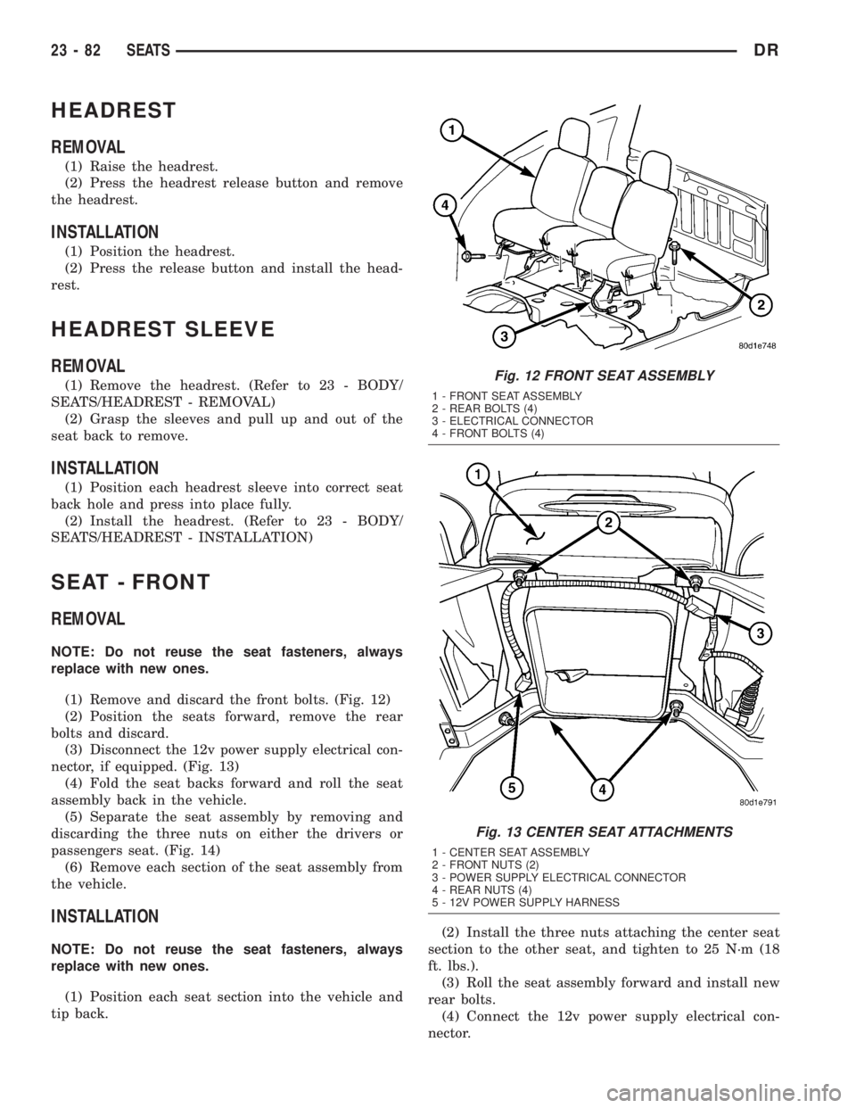
(1) Remove and discard the front bolts. (Fig. 12)
(2) Position the seats forward, remove the rear
bolts and discard.
(3) Disconnect the 12v power supply electrical con-
nector, if equipped. (Fig. 13)
(4) Fold the seat backs forward and roll the seat
assembly back in the vehicle.
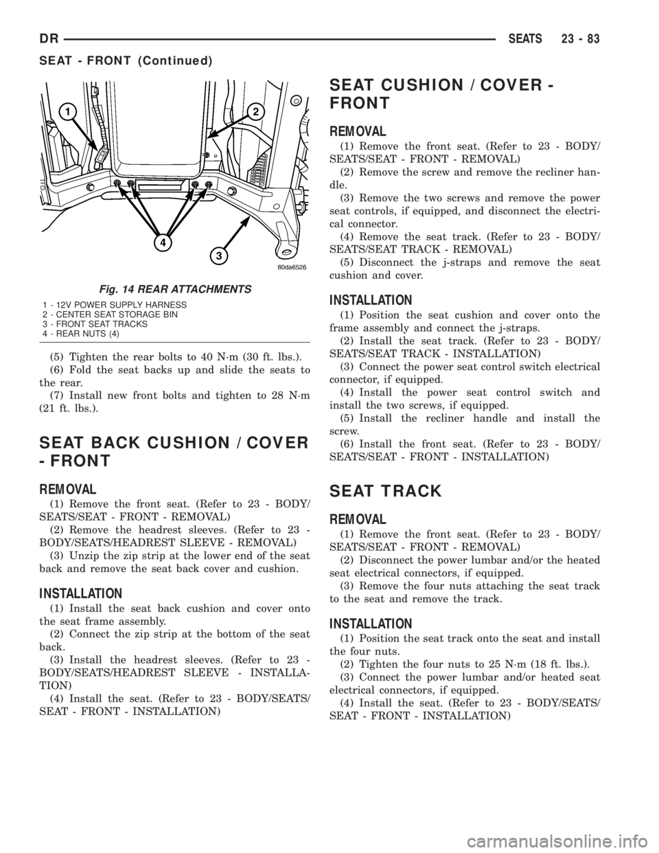
(5) Separate the seat assembly by removing and
discarding the three nuts on either the drivers or
passengers seat. (Fig. 14)
(6) Remove each section of the seat assembly from
the vehicle.
INSTALLATION
NOTE: Do not reuse the seat fasteners, always
replace with new ones.
(1) Position each seat section into the vehicle and
tip back.(2) Install the three nuts attaching the center seat
section to the other seat, and tighten to 25 N´m (18
ft. lbs.).
(3) Roll the seat assembly forward and install new
rear bolts.
(4) Connect the 12v power supply electrical con-
nector.
Fig. 12 FRONT SEAT ASSEMBLY
1 - FRONT SEAT ASSEMBLY
2 - REAR BOLTS (4)
3 - ELECTRICAL CONNECTOR
4 - FRONT BOLTS (4)
Fig. 13 CENTER SEAT ATTACHMENTS
1 - CENTER SEAT ASSEMBLY
2 - FRONT NUTS (2)
3 - POWER SUPPLY ELECTRICAL CONNECTOR
4 - REAR NUTS (4)
5 - 12V POWER SUPPLY HARNESS
23 - 82 SEATSDR
Page 2658 of 2895
(5) Tighten the rear bolts to 40 N´m (30 ft. lbs.).
(6) Fold the seat backs up and slide the seats to
the rear.
(7) Install new front bolts and tighten to 28 N´m
(21 ft. lbs.).
SEAT BACK CUSHION / COVER
- FRONT
REMOVAL
(1) Remove the front seat. (Refer to 23 - BODY/
SEATS/SEAT - FRONT - REMOVAL)
(2) Remove the headrest sleeves. (Refer to 23 -
BODY/SEATS/HEADREST SLEEVE - REMOVAL)
(3) Unzip the zip strip at the lower end of the seat
back and remove the seat back cover and cushion.
INSTALLATION
(1) Install the seat back cushion and cover onto
the seat frame assembly.
(2) Connect the zip strip at the bottom of the seat
back.
(3) Install the headrest sleeves. (Refer to 23 -
BODY/SEATS/HEADREST SLEEVE - INSTALLA-
TION)
(4) Install the seat. (Refer to 23 - BODY/SEATS/
SEAT - FRONT - INSTALLATION)
SEAT CUSHION / COVER -
FRONT
REMOVAL
(1) Remove the front seat. (Refer to 23 - BODY/
SEATS/SEAT - FRONT - REMOVAL)
(2) Remove the screw and remove the recliner han-
dle.
(3) Remove the two screws and remove the power
seat controls, if equipped, and disconnect the electri-
cal connector.
(4) Remove the seat track. (Refer to 23 - BODY/
SEATS/SEAT TRACK - REMOVAL)
(5) Disconnect the j-straps and remove the seat
cushion and cover.
INSTALLATION
(1) Position the seat cushion and cover onto the
frame assembly and connect the j-straps.
(2) Install the seat track. (Refer to 23 - BODY/
SEATS/SEAT TRACK - INSTALLATION)
(3) Connect the power seat control switch electrical
connector, if equipped.
(4) Install the power seat control switch and
install the two screws, if equipped.
(5) Install the recliner handle and install the
screw.
(6) Install the front seat. (Refer to 23 - BODY/
SEATS/SEAT - FRONT - INSTALLATION)
SEAT TRACK
REMOVAL
(1) Remove the front seat. (Refer to 23 - BODY/
SEATS/SEAT - FRONT - REMOVAL)
(2) Disconnect the power lumbar and/or the heated
seat electrical connectors, if equipped.
(3) Remove the four nuts attaching the seat track
to the seat and remove the track.
INSTALLATION
(1) Position the seat track onto the seat and install
the four nuts.
(2) Tighten the four nuts to 25 N´m (18 ft. lbs.).
(3) Connect the power lumbar and/or heated seat
electrical connectors, if equipped.
(4) Install the seat. (Refer to 23 - BODY/SEATS/
SEAT - FRONT - INSTALLATION)
Fig. 14 REAR ATTACHMENTS
1 - 12V POWER SUPPLY HARNESS
2 - CENTER SEAT STORAGE BIN
3 - FRONT SEAT TRACKS
4 - REAR NUTS (4)
DRSEATS 23 - 83
SEAT - FRONT (Continued)
Page 2659 of 2895
SEAT - REAR
REMOVAL
(1) Remove the load floor. (Refer to 23 - BODY/IN-
TERIOR/LOAD FLOOR - REMOVAL)
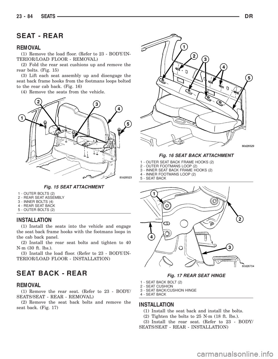
(2) Fold the rear seat cushions up and remove the
rear bolts. (Fig. 15)
(3) Lift each seat assembly up and disengage the
seat back frame hooks from the footmans loops bolted
to the rear cab back. (Fig. 16)
(4) Remove the seats from the vehicle.
INSTALLATION
(1) Install the seats into the vehicle and engage
the seat back frame hooks with the footmans loops in
the cab back panel.
(2) Install the rear seat bolts and tighten to 40
N´m (30 ft. lbs.).
(3) Install the load floor. (Refer to 23 - BODY/IN-
TERIOR/LOAD FLOOR - INSTALLATION)
SEAT BACK - REAR
REMOVAL
(1) Remove the rear seat. (Refer to 23 - BODY/
SEATS/SEAT - REAR - REMOVAL)
(2) Remove the seat back bolts and remove the
seat back. (Fig. 17)
INSTALLATION
(1) Install the seat back and install the bolts.
(2) Tighten the bolts to 25 N´m (18 ft. lbs.).
(3) Install the rear seat. (Refer to 23 - BODY/
SEATS/SEAT - REAR - INSTALLATION)
Fig. 15 SEAT ATTACHMENT
1 - OUTER BOLTS (2)
2 - REAR SEAT ASSEMBLY
3 - INNER BOLTS (4)
4 - REAR SEAT BACK
5 - OUTER BOLTS (2)
Fig. 16 SEAT BACK ATTACHMENT
1 - OUTER SEAT BACK FRAME HOOKS (2)
2 - OUTER FOOTMANS LOOP (2)
3 - INNER SEAT BACK FRAME HOOKS (2)
4 - INNER FOOTMANS LOOP (2)
5 - SEAT BACK
Fig. 17 REAR SEAT HINGE
1 - SEAT BACK BOLT (2)
2 - SEAT CUSHION
3 - SEAT BACK/CUSHION HINGE
4 - SEAT BACK
23 - 84 SEATSDR