radio antenna DODGE RAM 2003 Service Repair Manual
[x] Cancel search | Manufacturer: DODGE, Model Year: 2003, Model line: RAM, Model: DODGE RAM 2003Pages: 2895, PDF Size: 83.15 MB
Page 364 of 2895
AUDIO
TABLE OF CONTENTS
page page
AUDIO
DESCRIPTION..........................1
OPERATION............................1
DIAGNOSIS AND TESTING - AUDIO..........2
AMPLIFIER
DESCRIPTION..........................3
OPERATION............................3
REMOVAL.............................3
INSTALLATION..........................4
ANTENNA BODY & CABLE
DESCRIPTION..........................4
OPERATION............................4
DIAGNOSIS AND TESTING - ANTENNA BODY
AND CABLE..........................4
REMOVAL.............................6
INSTALLATION..........................6
INSTRUMENT PANEL ANTENNA CABLE
REMOVAL.............................6
INSTALLATION..........................7
RADIO
DESCRIPTION..........................7OPERATION............................7
REMOVAL.............................7
INSTALLATION..........................8
RADIO NOISE SUPPRESSION GROUND STRAP
DESCRIPTION..........................8
OPERATION............................8
REMOVAL.............................9
INSTALLATION.........................10
REMOTE SWITCHES
DESCRIPTION.........................10
OPERATION...........................10
DIAGNOSIS AND TESTING - REMOTE
SWITCHES..........................11
REMOVAL.............................12
INSTALLATION.........................12
SPEAKER
DESCRIPTION.........................12
OPERATION...........................12
DIAGNOSIS AND TESTING - SPEAKER......13
REMOVAL.............................13
INSTALLATION.........................15
AUDIO
DESCRIPTION
An audio system is standard factory-installed
equipment on this model. Several combinations of
radio receivers and speaker systems are offered. The
audio system uses an ignition switched source of bat-
tery current so that the system will only operate
when the ignition switch is in the RUN or ACCES-
SORY positions.
The audio system includes the following compo-
nents:
²Antenna
²Power amplifier (with premium speaker system
only)
²Radio noise suppression components
²Radio receiver
²Remote radio switches (if equipped)
²Speakers
Certain functions and features of the audio system
rely upon resources shared with other electronic
modules in the vehicle over the Programmable Com-
munication Interface (PCI) bus network. The data
bus network allows the sharing of sensor informa-
tion. For diagnosis of these electronic modules or of
the data bus network, the use of a DRB IIItscan tooland the proper Diagnostic Procedures manual are
recommended.
Refer to the appropriate wiring information for
complete standard and premium audio system circuit
diagrams. The wiring information includes proper
wire and connector repair procedures, further details
on wire harness routing and retention, as well as
pin-out and location views for the various wire har-
ness connectors, splices, and grounds.
OPERATION
The audio system components are designed to pro-
vide audio entertainment and information through
the reception, tuning and amplification of locally
broadcast radio signals in both the Amplitude Modu-
lating (AM) and Frequency Modulating (FM) com-
mercial frequency ranges.
The audio system components operate on battery
current received through a fuse in the Integrated
Power Module (IPM) on a fused ignition switch out-
put (run-acc) circuit so that the system will only
operate when the ignition switch is in the Run or
Accessory positions.
On vehicles that are equipped with the optional
remote radio switches, the Instrument Cluster
receives hard wired resistor multiplexed inputs from
the remote radio switches. The programming in the
DRAUDIO 8A - 1
Page 366 of 2895
CONDITION POSSIBLE CAUSES CORRECTION
CLOCK WILL NOT KEEP
SET TIME1. Fuse faulty. 1. Check Ignition-Off Draw (IOD) fuse in the
Integrated Power Module (IPM). Replace fuse, if
required.
2. Radio connector faulty. 2. Check for loose or corroded radio connector.
Repair, if required.
3. Wiring faulty. 3. Check for battery voltage at radio connector.
Repair wiring, if required.
4. Radio ground faulty. 4. Check for continuity between radio chassis and
a known good ground. There should be
continuity. Repair ground, if required.
5. Radio faulty. 5. Refer to appropriate Diagnostic Service
Manual.
POOR RADIO RECEPTION 1. Antenna faulty. 1. (Refer to 8 - ELECTRICAL/AUDIO/ANTENNA
BODY & CABLE - DIAGNOSIS AND TESTING).
2. Radio ground faulty. 2. Check for continuity between radio chassis and
a known good ground. There should be
continuity. Repair ground, if required.
3. Radio noise suppression
faulty.3. Repair or replace ground strap as necessary.
4. Radio faulty. 4. Refer to appropriate Diagnostic Service
Manual.
NO/POOR TAPE
OPERATION1. Faulty tape. 1. Insert known good tape and test operation.
2. Foreign objects behind
tape door.2. Remove foreign objects and test operation.
3. Dirty cassette tape head. 3. Clean head with Mopar Cassette Head
Cleaner.
4. Faulty tape deck. 4. Exchange or replace radio, if required.
NO COMPACT DISC
OPERATION1. Faulty CD. 1. Insert known good CD and test operation.
2. Foreign material on CD. 2. Clean CD and test operation.
3. Condensation on CD or
optics.3. Allow temperature of vehicle interior to stabilize
and test operation.
4. Faulty CD player. 4. Refer to appropriate Diagnostic Service
Manual.
AMPLIFIER
DESCRIPTION
The optional Infinity premium speaker system
includes a separate Infinity audio power amplifier.
The amplifier is a six channel unit and is rated at
240 total output watts. The amplifier is located
behind the glove box.
OPERATION
The power amplifier electronically increases the
frequency response of the normal audio signal output
from the radio amplifier in order to improve the
acoustic performance of the speakers. On vehiclesequipped with an amplifier, the amplifier section of
the radio becomes a pre-amplifier.
The amplifier receives audio signal inputs for
speaker channels from the radio, then sends ampli-
fied audio outputs through six separate channels
with dedicated feed and return circuits to the indi-
vidual speakers.
REMOVAL
(1) Disconnect and isolate the battery negative
cable.
(2) Remove glove box (Refer to 23 - BODY/IN-
STRUMENT PANEL/GLOVE BOX - REMOVAL).
DRAUDIO 8A - 3
AUDIO (Continued)
Page 367 of 2895
(3) Remove instrument panel center bezel (Refer to
23 - BODY/INSTRUMENT PANEL/INSTRUMENT
PANEL CENTER BEZEL - REMOVAL).
(4) Remove instrument panel lower right center
bezel (Refer to 23 - BODY/INSTRUMENT PANEL/IP
LOWER RIGHT CENTER BEZEL - REMOVAL).
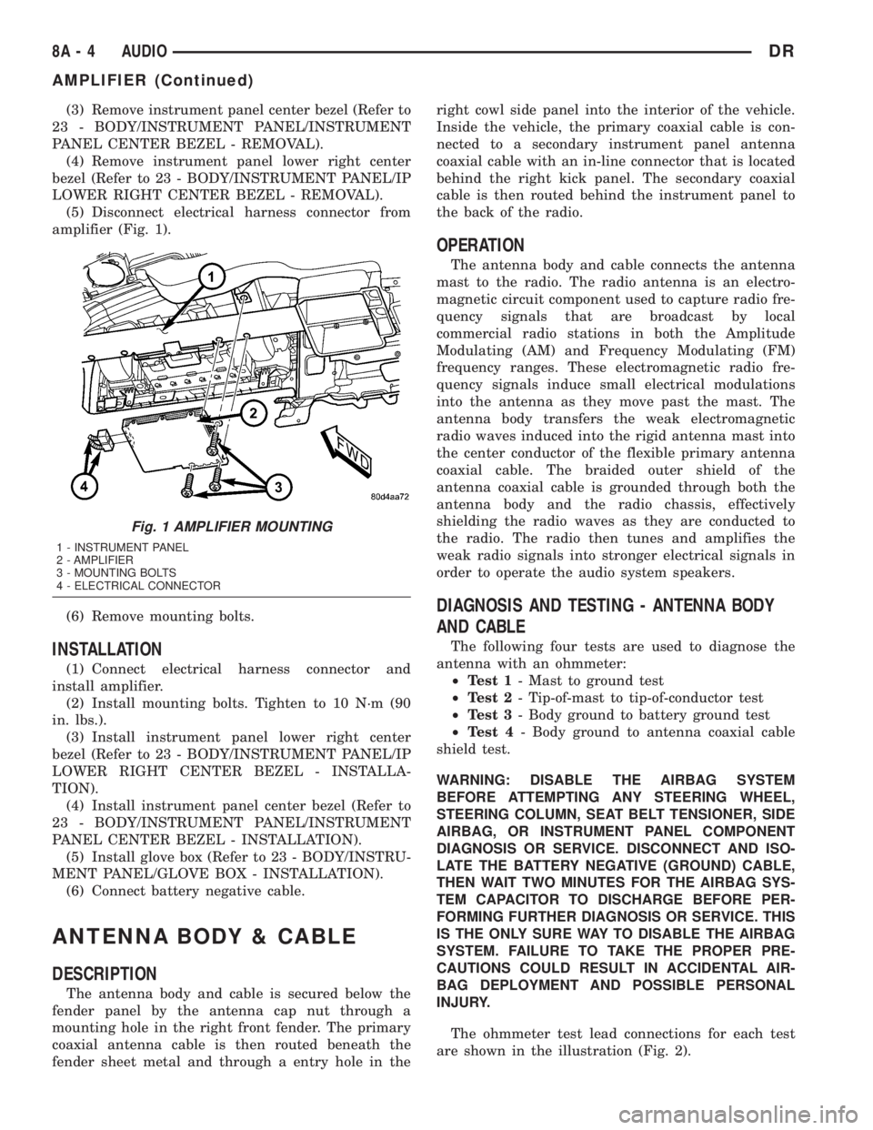
(5) Disconnect electrical harness connector from
amplifier (Fig. 1).
(6) Remove mounting bolts.
INSTALLATION
(1) Connect electrical harness connector and
install amplifier.
(2) Install mounting bolts. Tighten to 10 N´m (90
in. lbs.).
(3) Install instrument panel lower right center
bezel (Refer to 23 - BODY/INSTRUMENT PANEL/IP
LOWER RIGHT CENTER BEZEL - INSTALLA-
TION).
(4) Install instrument panel center bezel (Refer to
23 - BODY/INSTRUMENT PANEL/INSTRUMENT
PANEL CENTER BEZEL - INSTALLATION).
(5) Install glove box (Refer to 23 - BODY/INSTRU-
MENT PANEL/GLOVE BOX - INSTALLATION).
(6) Connect battery negative cable.
ANTENNA BODY & CABLE
DESCRIPTION
The antenna body and cable is secured below the
fender panel by the antenna cap nut through a
mounting hole in the right front fender. The primary
coaxial antenna cable is then routed beneath the
fender sheet metal and through a entry hole in theright cowl side panel into the interior of the vehicle.
Inside the vehicle, the primary coaxial cable is con-
nected to a secondary instrument panel antenna
coaxial cable with an in-line connector that is located
behind the right kick panel. The secondary coaxial
cable is then routed behind the instrument panel to
the back of the radio.
OPERATION
The antenna body and cable connects the antenna
mast to the radio. The radio antenna is an electro-
magnetic circuit component used to capture radio fre-
quency signals that are broadcast by local
commercial radio stations in both the Amplitude
Modulating (AM) and Frequency Modulating (FM)
frequency ranges. These electromagnetic radio fre-
quency signals induce small electrical modulations
into the antenna as they move past the mast. The
antenna body transfers the weak electromagnetic
radio waves induced into the rigid antenna mast into
the center conductor of the flexible primary antenna
coaxial cable. The braided outer shield of the
antenna coaxial cable is grounded through both the
antenna body and the radio chassis, effectively
shielding the radio waves as they are conducted to
the radio. The radio then tunes and amplifies the
weak radio signals into stronger electrical signals in
order to operate the audio system speakers.
DIAGNOSIS AND TESTING - ANTENNA BODY
AND CABLE
The following four tests are used to diagnose the
antenna with an ohmmeter:
²Test 1- Mast to ground test
²Test 2- Tip-of-mast to tip-of-conductor test
²Test 3- Body ground to battery ground test
²Test 4- Body ground to antenna coaxial cable
shield test.
WARNING: DISABLE THE AIRBAG SYSTEM
BEFORE ATTEMPTING ANY STEERING WHEEL,
STEERING COLUMN, SEAT BELT TENSIONER, SIDE
AIRBAG, OR INSTRUMENT PANEL COMPONENT
DIAGNOSIS OR SERVICE. DISCONNECT AND ISO-
LATE THE BATTERY NEGATIVE (GROUND) CABLE,
THEN WAIT TWO MINUTES FOR THE AIRBAG SYS-
TEM CAPACITOR TO DISCHARGE BEFORE PER-
FORMING FURTHER DIAGNOSIS OR SERVICE. THIS
IS THE ONLY SURE WAY TO DISABLE THE AIRBAG
SYSTEM. FAILURE TO TAKE THE PROPER PRE-
CAUTIONS COULD RESULT IN ACCIDENTAL AIR-
BAG DEPLOYMENT AND POSSIBLE PERSONAL
INJURY.
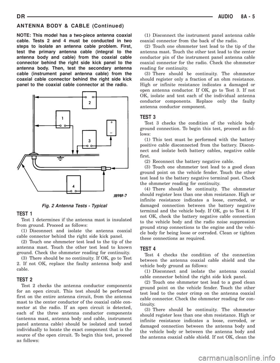
The ohmmeter test lead connections for each test
are shown in the illustration (Fig. 2).
Fig. 1 AMPLIFIER MOUNTING
1 - INSTRUMENT PANEL
2 - AMPLIFIER
3 - MOUNTING BOLTS
4 - ELECTRICAL CONNECTOR
8A - 4 AUDIODR
AMPLIFIER (Continued)
Page 368 of 2895
NOTE: This model has a two-piece antenna coaxial
cable. Tests 2 and 4 must be conducted in two
steps to isolate an antenna cable problem. First,
test the primary antenna cable (integral to the
antenna body and cable) from the coaxial cable
connector behind the right side kick panel to the
antenna body. Then, test the secondary antenna
cable (instrument panel antenna cable) from the
coaxial cable connector behind the right side kick
panel to the coaxial cable connector at the radio.
TEST 1
Test 1 determines if the antenna mast is insulated
from ground. Proceed as follows:
(1) Disconnect and isolate the antenna coaxial
cable connector behind the right side kick panel.
(2) Touch one ohmmeter test lead to the tip of the
antenna mast. Touch the other test lead to known
ground. Check the ohmmeter reading for continuity.
(3) There should be no continuity. If OK, go to Test
2. If not OK, replace the faulty antenna body and
cable.
TEST 2
Test 2 checks the antenna conductor components
for an open circuit. This test should be performed
first on the entire antenna circuit, from the antenna
mast to the center conductor of the coaxial cable con-
nector at the radio. If an open circuit is detected,
each of the three antenna conductor components
(antenna mast, antenna body and cable, instrument
panel antenna cable) should be isolated and tested
individually to locate the exact component that is the
source of the open circuit. To begin this test, proceed
as follows:(1) Disconnect the instrument panel antenna cable
coaxial connector from the back of the radio.
(2) Touch one ohmmeter test lead to the tip of the
antenna mast. Touch the other test lead to the center
conductor pin of the instrument panel antenna cable
coaxial connector for the radio. Check the ohmmeter
reading for continuity.
(3) There should be continuity. The ohmmeter
should register only a fraction of an ohm resistance.
High or infinite resistance indicates a damaged or
open antenna conductor. If OK, go to Test 3. If not
OK, isolate and test each of the individual antenna
conductor components. Replace only the faulty
antenna conductor component.
TEST 3
Test 3 checks the condition of the vehicle body
ground connection. To begin this test, proceed as fol-
lows:
(1) This test must be performed with the battery
positive cable disconnected from the battery. Discon-
nect and isolate both battery cables, negative cable
first.
(2) Reconnect the battery negative cable.
(3) Touch one ohmmeter test lead to a good clean
ground point on the vehicle fender. Touch the other
test lead to the battery negative terminal post. Check
the ohmmeter reading for continuity.
(4) There should be continuity. The ohmmeter
should register less than one ohm resistance. High or
infinite resistance indicates a loose, corroded, or
damaged connection between the battery negative
terminal and the vehicle body. If OK, go to Test 4. If
not OK, check the battery negative cable connection
to the vehicle body and the radio noise suppression
ground strap connections to the engine and the vehi-
cle body for being loose or corroded. Clean or tighten
these connections as required.
TEST 4
Test 4 checks the condition of the connection
between the antenna coaxial cable shield and the
vehicle body ground as follows:
(1) Disconnect and isolate the antenna coaxial
cable connector behind the right side kick panel.
(2) Touch one ohmmeter test lead to a good clean
ground point on the vehicle fender. Touch the other
test lead to the outer crimp on the antenna coaxial
cable connector. Check the ohmmeter reading for con-
tinuity.
(3) There should be continuity. The ohmmeter
should register less than one ohm resistance. High or
infinite resistance indicates a loose, corroded, or
damaged connection between the antenna body and
the vehicle body or between the antenna body and
the antenna coaxial cable shield. If not OK, clean the
Fig. 2 Antenna Tests - Typical
DRAUDIO 8A - 5
ANTENNA BODY & CABLE (Continued)
Page 369 of 2895
antenna body to fender mating surfaces and tighten
the antenna cap nut to specifications.
(4) Check the resistance again with an ohmmeter.
If the resistance is still more then one ohm, replace
the faulty antenna body and cable.
REMOVAL
(1) Disconnect and isolate the battery negative
cable.
(2) Remove the right side kick panel.
(3) Disconnect antenna body cable from instru-
ment panel cable.
(4) Securely tie a suitable length of cord or twine
to the antenna half of the coaxial cable connector.
This cord will be used to pull the cable back into
position during installation.
(5) Remove the antenna mast.
(6) Remove the antenna cap nut using an antenna
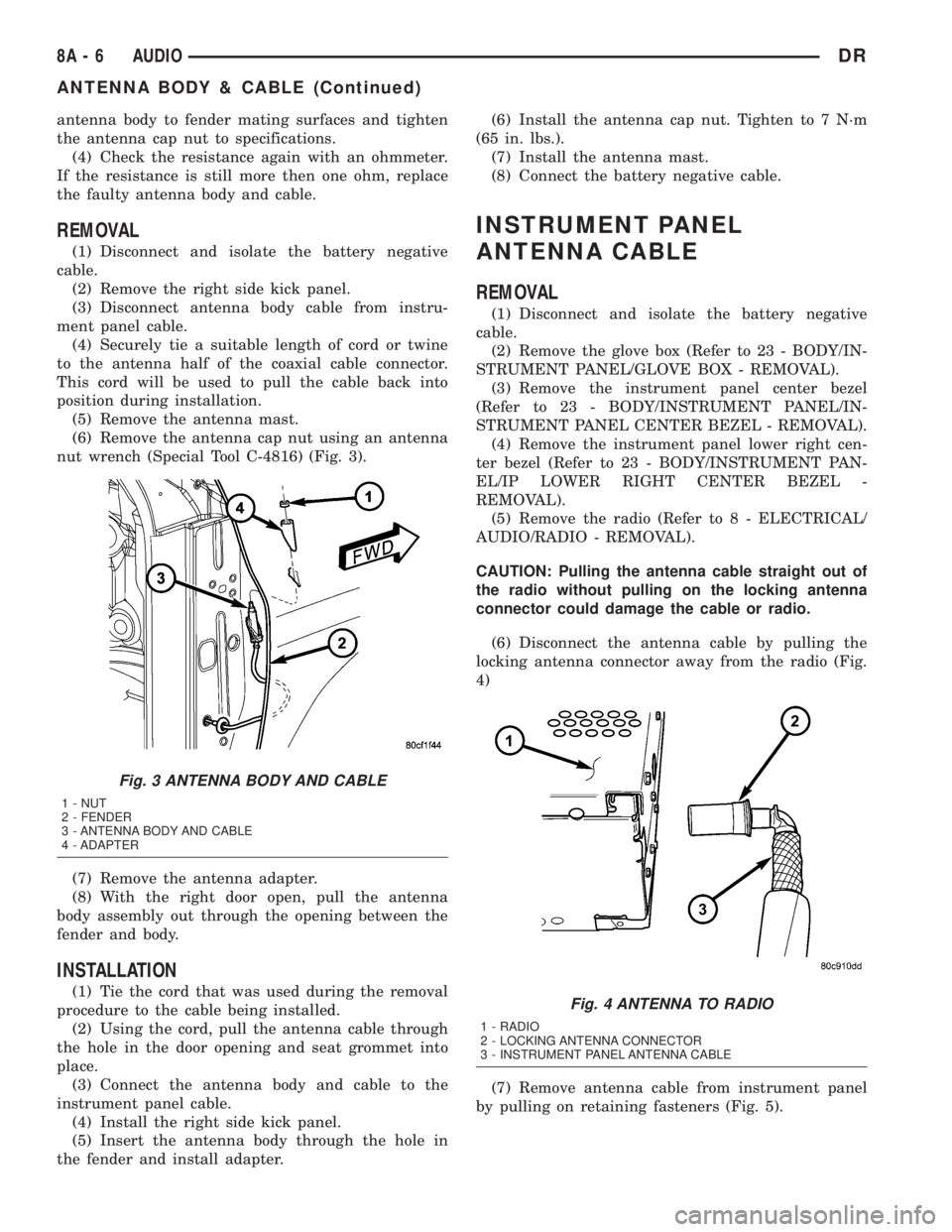
nut wrench (Special Tool C-4816) (Fig. 3).
(7) Remove the antenna adapter.
(8) With the right door open, pull the antenna
body assembly out through the opening between the
fender and body.
INSTALLATION
(1) Tie the cord that was used during the removal
procedure to the cable being installed.
(2) Using the cord, pull the antenna cable through
the hole in the door opening and seat grommet into
place.
(3) Connect the antenna body and cable to the
instrument panel cable.
(4) Install the right side kick panel.
(5) Insert the antenna body through the hole in
the fender and install adapter.(6) Install the antenna cap nut. Tighten to 7 N´m
(65 in. lbs.).
(7) Install the antenna mast.
(8) Connect the battery negative cable.
INSTRUMENT PANEL
ANTENNA CABLE
REMOVAL
(1) Disconnect and isolate the battery negative
cable.
(2) Remove the glove box (Refer to 23 - BODY/IN-
STRUMENT PANEL/GLOVE BOX - REMOVAL).
(3) Remove the instrument panel center bezel
(Refer to 23 - BODY/INSTRUMENT PANEL/IN-
STRUMENT PANEL CENTER BEZEL - REMOVAL).
(4) Remove the instrument panel lower right cen-
ter bezel (Refer to 23 - BODY/INSTRUMENT PAN-
EL/IP LOWER RIGHT CENTER BEZEL -
REMOVAL).
(5) Remove the radio (Refer to 8 - ELECTRICAL/
AUDIO/RADIO - REMOVAL).
CAUTION: Pulling the antenna cable straight out of
the radio without pulling on the locking antenna
connector could damage the cable or radio.
(6) Disconnect the antenna cable by pulling the
locking antenna connector away from the radio (Fig.
4)
(7) Remove antenna cable from instrument panel
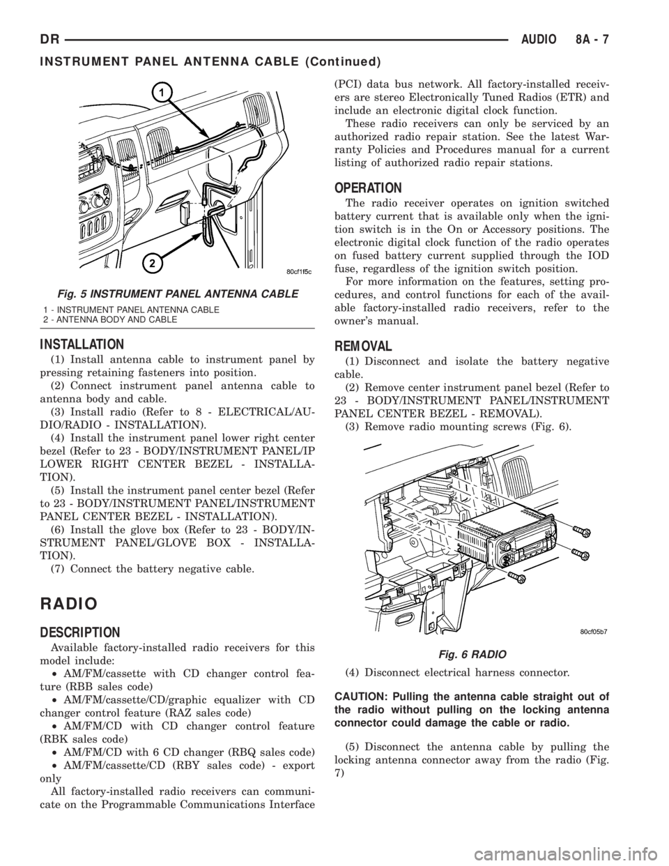
by pulling on retaining fasteners (Fig. 5).
Fig. 3 ANTENNA BODY AND CABLE
1 - NUT
2 - FENDER
3 - ANTENNA BODY AND CABLE
4 - ADAPTER
Fig. 4 ANTENNA TO RADIO
1 - RADIO
2 - LOCKING ANTENNA CONNECTOR
3 - INSTRUMENT PANEL ANTENNA CABLE
8A - 6 AUDIODR
ANTENNA BODY & CABLE (Continued)
Page 370 of 2895
INSTALLATION
(1) Install antenna cable to instrument panel by
pressing retaining fasteners into position.
(2) Connect instrument panel antenna cable to
antenna body and cable.
(3) Install radio (Refer to 8 - ELECTRICAL/AU-
DIO/RADIO - INSTALLATION).
(4) Install the instrument panel lower right center
bezel (Refer to 23 - BODY/INSTRUMENT PANEL/IP
LOWER RIGHT CENTER BEZEL - INSTALLA-
TION).
(5) Install the instrument panel center bezel (Refer
to 23 - BODY/INSTRUMENT PANEL/INSTRUMENT
PANEL CENTER BEZEL - INSTALLATION).
(6) Install the glove box (Refer to 23 - BODY/IN-
STRUMENT PANEL/GLOVE BOX - INSTALLA-
TION).
(7) Connect the battery negative cable.
RADIO
DESCRIPTION
Available factory-installed radio receivers for this
model include:
²AM/FM/cassette with CD changer control fea-
ture (RBB sales code)
²AM/FM/cassette/CD/graphic equalizer with CD
changer control feature (RAZ sales code)
²AM/FM/CD with CD changer control feature
(RBK sales code)
²AM/FM/CD with 6 CD changer (RBQ sales code)
²AM/FM/cassette/CD (RBY sales code) - export
only
All factory-installed radio receivers can communi-
cate on the Programmable Communications Interface(PCI) data bus network. All factory-installed receiv-
ers are stereo Electronically Tuned Radios (ETR) and
include an electronic digital clock function.
These radio receivers can only be serviced by an
authorized radio repair station. See the latest War-
ranty Policies and Procedures manual for a current
listing of authorized radio repair stations.
OPERATION
The radio receiver operates on ignition switched
battery current that is available only when the igni-
tion switch is in the On or Accessory positions. The
electronic digital clock function of the radio operates
on fused battery current supplied through the IOD
fuse, regardless of the ignition switch position.
For more information on the features, setting pro-
cedures, and control functions for each of the avail-
able factory-installed radio receivers, refer to the
owner's manual.
REMOVAL
(1) Disconnect and isolate the battery negative
cable.
(2) Remove center instrument panel bezel (Refer to
23 - BODY/INSTRUMENT PANEL/INSTRUMENT
PANEL CENTER BEZEL - REMOVAL).
(3) Remove radio mounting screws (Fig. 6).
(4) Disconnect electrical harness connector.
CAUTION: Pulling the antenna cable straight out of
the radio without pulling on the locking antenna
connector could damage the cable or radio.
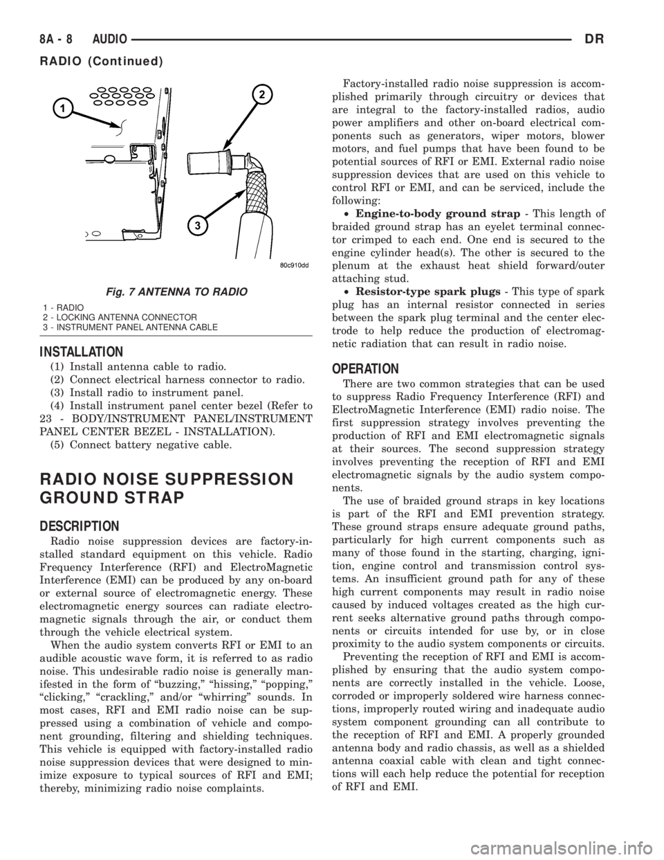
(5) Disconnect the antenna cable by pulling the
locking antenna connector away from the radio (Fig.
7)
Fig. 5 INSTRUMENT PANEL ANTENNA CABLE
1 - INSTRUMENT PANEL ANTENNA CABLE
2 - ANTENNA BODY AND CABLE
Fig. 6 RADIO
DRAUDIO 8A - 7
INSTRUMENT PANEL ANTENNA CABLE (Continued)
Page 371 of 2895
INSTALLATION
(1) Install antenna cable to radio.
(2) Connect electrical harness connector to radio.
(3) Install radio to instrument panel.
(4) Install instrument panel center bezel (Refer to
23 - BODY/INSTRUMENT PANEL/INSTRUMENT
PANEL CENTER BEZEL - INSTALLATION).
(5) Connect battery negative cable.
RADIO NOISE SUPPRESSION
GROUND STRAP
DESCRIPTION
Radio noise suppression devices are factory-in-
stalled standard equipment on this vehicle. Radio
Frequency Interference (RFI) and ElectroMagnetic
Interference (EMI) can be produced by any on-board
or external source of electromagnetic energy. These
electromagnetic energy sources can radiate electro-
magnetic signals through the air, or conduct them
through the vehicle electrical system.
When the audio system converts RFI or EMI to an
audible acoustic wave form, it is referred to as radio
noise. This undesirable radio noise is generally man-
ifested in the form of ªbuzzing,º ªhissing,º ªpopping,º
ªclicking,º ªcrackling,º and/or ªwhirringº sounds. In
most cases, RFI and EMI radio noise can be sup-
pressed using a combination of vehicle and compo-
nent grounding, filtering and shielding techniques.
This vehicle is equipped with factory-installed radio
noise suppression devices that were designed to min-
imize exposure to typical sources of RFI and EMI;
thereby, minimizing radio noise complaints.Factory-installed radio noise suppression is accom-
plished primarily through circuitry or devices that
are integral to the factory-installed radios, audio
power amplifiers and other on-board electrical com-
ponents such as generators, wiper motors, blower
motors, and fuel pumps that have been found to be
potential sources of RFI or EMI. External radio noise
suppression devices that are used on this vehicle to
control RFI or EMI, and can be serviced, include the
following:
²Engine-to-body ground strap- This length of
braided ground strap has an eyelet terminal connec-
tor crimped to each end. One end is secured to the
engine cylinder head(s). The other is secured to the
plenum at the exhaust heat shield forward/outer
attaching stud.
²Resistor-type spark plugs- This type of spark
plug has an internal resistor connected in series
between the spark plug terminal and the center elec-
trode to help reduce the production of electromag-
netic radiation that can result in radio noise.
OPERATION
There are two common strategies that can be used
to suppress Radio Frequency Interference (RFI) and
ElectroMagnetic Interference (EMI) radio noise. The
first suppression strategy involves preventing the
production of RFI and EMI electromagnetic signals
at their sources. The second suppression strategy
involves preventing the reception of RFI and EMI
electromagnetic signals by the audio system compo-
nents.
The use of braided ground straps in key locations
is part of the RFI and EMI prevention strategy.
These ground straps ensure adequate ground paths,
particularly for high current components such as
many of those found in the starting, charging, igni-
tion, engine control and transmission control sys-
tems. An insufficient ground path for any of these
high current components may result in radio noise
caused by induced voltages created as the high cur-
rent seeks alternative ground paths through compo-
nents or circuits intended for use by, or in close
proximity to the audio system components or circuits.
Preventing the reception of RFI and EMI is accom-
plished by ensuring that the audio system compo-
nents are correctly installed in the vehicle. Loose,
corroded or improperly soldered wire harness connec-
tions, improperly routed wiring and inadequate audio
system component grounding can all contribute to
the reception of RFI and EMI. A properly grounded
antenna body and radio chassis, as well as a shielded
antenna coaxial cable with clean and tight connec-
tions will each help reduce the potential for reception
of RFI and EMI.
Fig. 7 ANTENNA TO RADIO
1 - RADIO
2 - LOCKING ANTENNA CONNECTOR
3 - INSTRUMENT PANEL ANTENNA CABLE
8A - 8 AUDIODR
RADIO (Continued)
Page 394 of 2895
(2) Tighten bolts. Refer to torque specifications.
(3) Check pin connectors in the PCM and the three
32±way connectors (four 38±way connectors if
equipped with NGC) for corrosion or damage. Also,
the pin heights in connectors should all be same.
Repair as necessary before installing connectors.
(4) Install three 32±way connectors (four 38±way
connectors if equipped with NGC).
(5) Install cover over electrical connectors. Cover
snaps onto PCM.
(6) Install negative battery cable.
(7) Use the DRB scan tool to reprogram new PCM
with vehicles original Vehicle Identification Number
(VIN) and original vehicle mileage.
SENTRY KEY IMMOBILIZER
MODULE
DESCRIPTION
The Sentry Key Immobilizer Module (SKIM) con-
tains a Radio Frequency (RF) transceiver and a cen-
tral processing unit, which includes the Sentry Key
Immobilizer System (SKIS) program logic. The SKIS
programming enables the SKIM to program and
retain in memory the codes of at least two, but no
more than eight electronically coded Sentry Key
transponders. The SKIS programming also enables
the SKIM to communicate over the Programmable
Communication Interface (PCI) bus network with the
Powertrain Control Module (PCM), and/or the
DRBIIItscan tool.
OPERATION
The SKIM transmits and receives RF signals
through a tuned antenna enclosed within a molded
plastic ring that is integral to the SKIM housing.
When the SKIM is properly installed on the steering
column, the antenna ring is oriented around the igni-
tion lock cylinder housing. This antenna ring must be
located within eight millimeters (0.31 inches) of the
Sentry Key in order to ensure proper RF communica-
tion between the SKIM and the Sentry Key tran-
sponder.
For added system security, each SKIM is pro-
grammed with a unique ªSecret Keyº code and a
security code. The SKIM keeps the ªSecret Keyº code
in memory. The SKIM also sends the ªSecret Keyº
code to each of the programmed Sentry Key tran-
sponders. The security code is used by the assembly
plant to access the SKIS for initialization, or by the
dealer technician to access the system for service.
The SKIM also stores in its memory the Vehicle
Identification Number (VIN), which it learns through
a PCI bus message from the PCM during initializa-
tion.The SKIM and the PCM both use software that
includes a rolling code algorithm strategy, which
helps to reduce the possibility of unauthorized SKIS
disarming. The rolling code algorithm ensures secu-
rity by preventing an override of the SKIS through
the unauthorized substitution of the SKIM or the
PCM. However, the use of this strategy also means
that replacement of either the SKIM or the PCM
units will require a system initialization procedure to
restore system operation.
When the ignition switch is turned to the ON or
START positions, the SKIM transmits an RF signal
to excite the Sentry Key transponder. The SKIM then
listens for a return RF signal from the transponder
of the Sentry Key that is inserted in the ignition lock
cylinder. If the SKIM receives an RF signal with
valid ªSecret Keyº and transponder identification
codes, the SKIM sends a ªvalid keyº message to the
PCM over the PCI bus. If the SKIM receives an
invalid RF signal or no response, it sends ªinvalid
keyº messages to the PCM. The PCM will enable or
disable engine operation based upon the status of the
SKIM messages.
The SKIM also sends messages to the Instrument
Cluster which controls the VTSS indicator LED. The
SKIM sends messages to the Instrument Cluster to
turn the LED on for about three seconds when the
ignition switch is turned to the ON position as a bulb
test. After completion of the bulb test, the SKIM
sends bus messages to keep the LED off for a dura-
tion of about one second. Then the SKIM sends mes-
sages to turn the LED on or off based upon the
results of the SKIS self-tests. If the VTSS indicator
LED comes on and stays on after the bulb test, it
indicates that the SKIM has detected a system mal-
function and/or that the SKIS has become inopera-
tive.
If the SKIM detects an invalid key when the igni-
tion switch is turned to the ON position, it sends
messages to flash the VTSS indicator LED. The
SKIM can also send messages to flash the LED as an
indication to the customer that the SKIS has been
placed in it's ªCustomer Learnº programming mode.
See Sentry Key Immobilizer System Transponder
Programming in this section for more information on
the ªCustomer Learnº programming mode.
For diagnosis or initialization of the SKIM and the
PCM, a DRBIIItscan tool and the proper Powertrain
Diagnostic Procedures manual are required. The
SKIM cannot be repaired and, if faulty or damaged,
the unit must be replaced.
DRELECTRONIC CONTROL MODULES 8E - 13
POWERTRAIN CONTROL MODULE (Continued)
Page 2630 of 2895
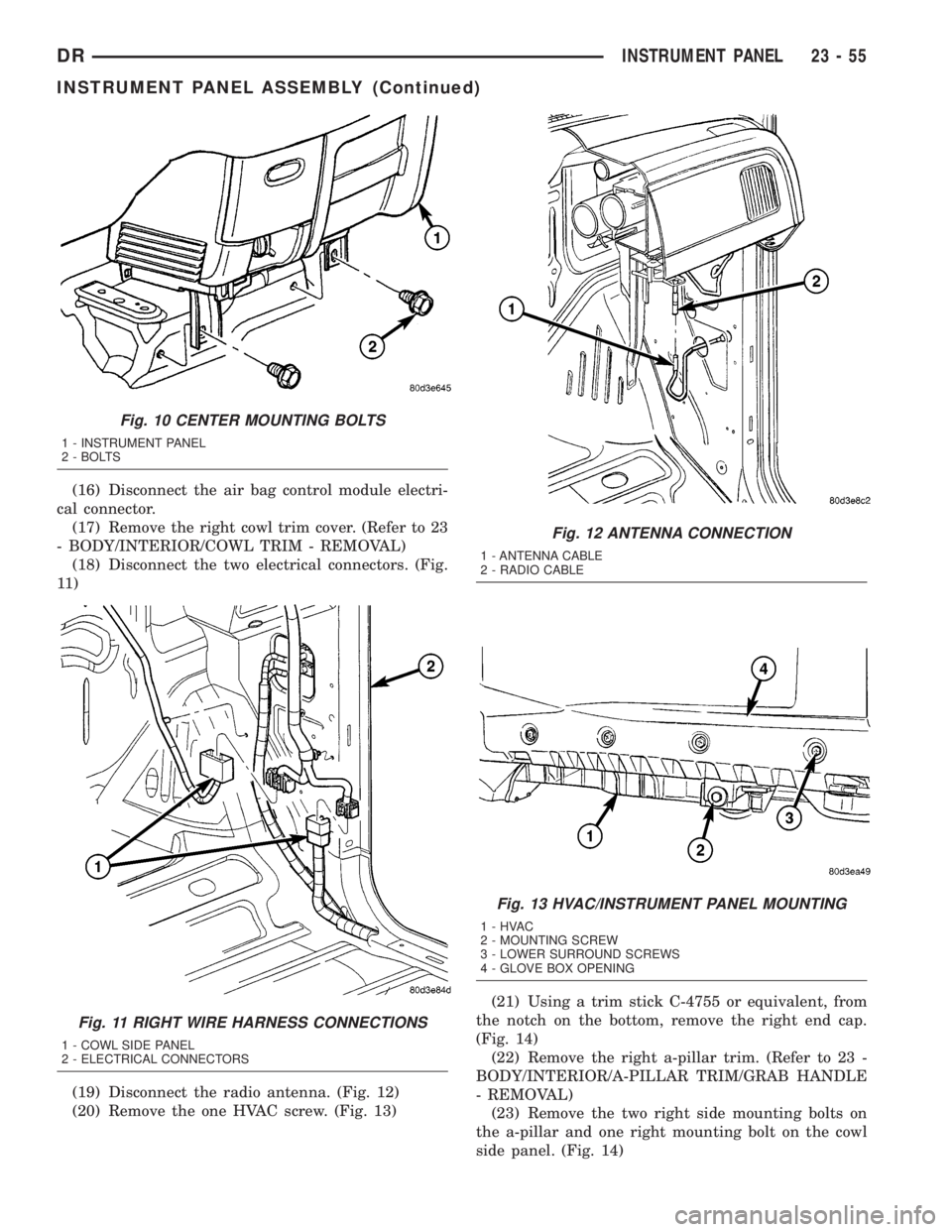
(16) Disconnect the air bag control module electri-
cal connector.
(17) Remove the right cowl trim cover. (Refer to 23
- BODY/INTERIOR/COWL TRIM - REMOVAL)
(18) Disconnect the two electrical connectors. (Fig.
11 )
(19) Disconnect the radio antenna. (Fig. 12)
(20) Remove the one HVAC screw. (Fig. 13)(21) Using a trim stick C-4755 or equivalent, from
the notch on the bottom, remove the right end cap.
(Fig. 14)
(22) Remove the right a-pillar trim. (Refer to 23 -
BODY/INTERIOR/A-PILLAR TRIM/GRAB HANDLE
- REMOVAL)
(23) Remove the two right side mounting bolts on
the a-pillar and one right mounting bolt on the cowl
side panel. (Fig. 14)
Fig. 10 CENTER MOUNTING BOLTS
1 - INSTRUMENT PANEL
2 - BOLTS
Fig. 11 RIGHT WIRE HARNESS CONNECTIONS
1 - COWL SIDE PANEL
2 - ELECTRICAL CONNECTORS
Fig. 12 ANTENNA CONNECTION
1 - ANTENNA CABLE
2 - RADIO CABLE
Fig. 13 HVAC/INSTRUMENT PANEL MOUNTING
1-HVAC
2 - MOUNTING SCREW
3 - LOWER SURROUND SCREWS
4 - GLOVE BOX OPENING
DRINSTRUMENT PANEL 23 - 55
INSTRUMENT PANEL ASSEMBLY (Continued)
Page 2632 of 2895
(11) Install the right a-pillar trim panel. (Refer to
23 - BODY/INTERIOR/A-PILLAR TRIM - INSTAL-
LATION)
(12) Position the right end cap and seat the
attachment clips fully.
(13) Install the one HVAC mounting screw.
(14) Connect the radio antenna.
(15) Connect the two electrical connectors at the
right cowl panel.
(16) Install the right cowl trim cover. (Refer to 23 -
BODY/INTERIOR/COWL TRIM - INSTALLATION)
(17) Connect the air bag control module electrical
connector.
(18) Install the center bracket bolts and tighten to
12 N´m (9 ft. lbs.).
(19) Install the floor console, if equipped. (Refer to
23 - BODY/INTERIOR/FLOOR CONSOLE - INSTAL-
LATION)
(20) Install the air bag control module cover, if
equipped.
(21) Connect the park brake release handle actua-
tor rod.
(22) Install the hood release handle and tighten
the screws.
(23) Install the two bolts at the column support
bracket and tighten to 14 N´m (10 ft. lbs.).
(24) Install the steering column. (Refer to 19 -
STEERING/COLUMN - INSTALLATION)
(25) Connect the wire harness electrical connectors
above the brake pedal.
(26) Install the two top instrument panel bolts and
tighten to 12 N´m (9 ft. lbs.).
(27) Install the four top instrument panel screws.
(28) Install the instrument panel top cover. (Refer
to 23 - BODY/INSTRUMENT PANEL/INSTRUMENT
PANEL TOP COVER - INSTALLATION)
INSTRUMENT PANEL
HEADLAMP SWITCH BEZEL
REMOVAL
WARNING: ON VEHICLES EQUIPPED WITH AIR-
BAGS, DISABLE THE AIRBAG SYSTEM BEFORE
ATTEMPTING ANY STEERING WHEEL, STEERING
COLUMN, SEAT BELT TENSIONER, OR INSTRU-
MENT PANEL COMPONENT DIAGNOSIS OR SER-
VICE. DISCONNECT AND ISOLATE THE BATTERY
NEGATIVE (GROUND) CABLE, THEN WAIT TWO
MINUTES FOR THE AIRBAG SYSTEM CAPACITOR
TO DISCHARGE BEFORE PERFORMING FURTHER
DIAGNOSIS OR SERVICE. THIS IS THE ONLY SURE
WAY TO DISABLE THE AIRBAG SYSTEM. FAILURE
TO TAKE THE PROPER PRECAUTIONS COULDRESULT IN ACCIDENTAL AIRBAG DEPLOYMENT
AND POSSIBLE PERSONAL INJURY.
(1) Using a trim stick C-4755 or equivalent,
release the top clips on the steering column opening
cover and the lower drivers side bezel.
(2) Using a trim stick C-4755 or equivalent,
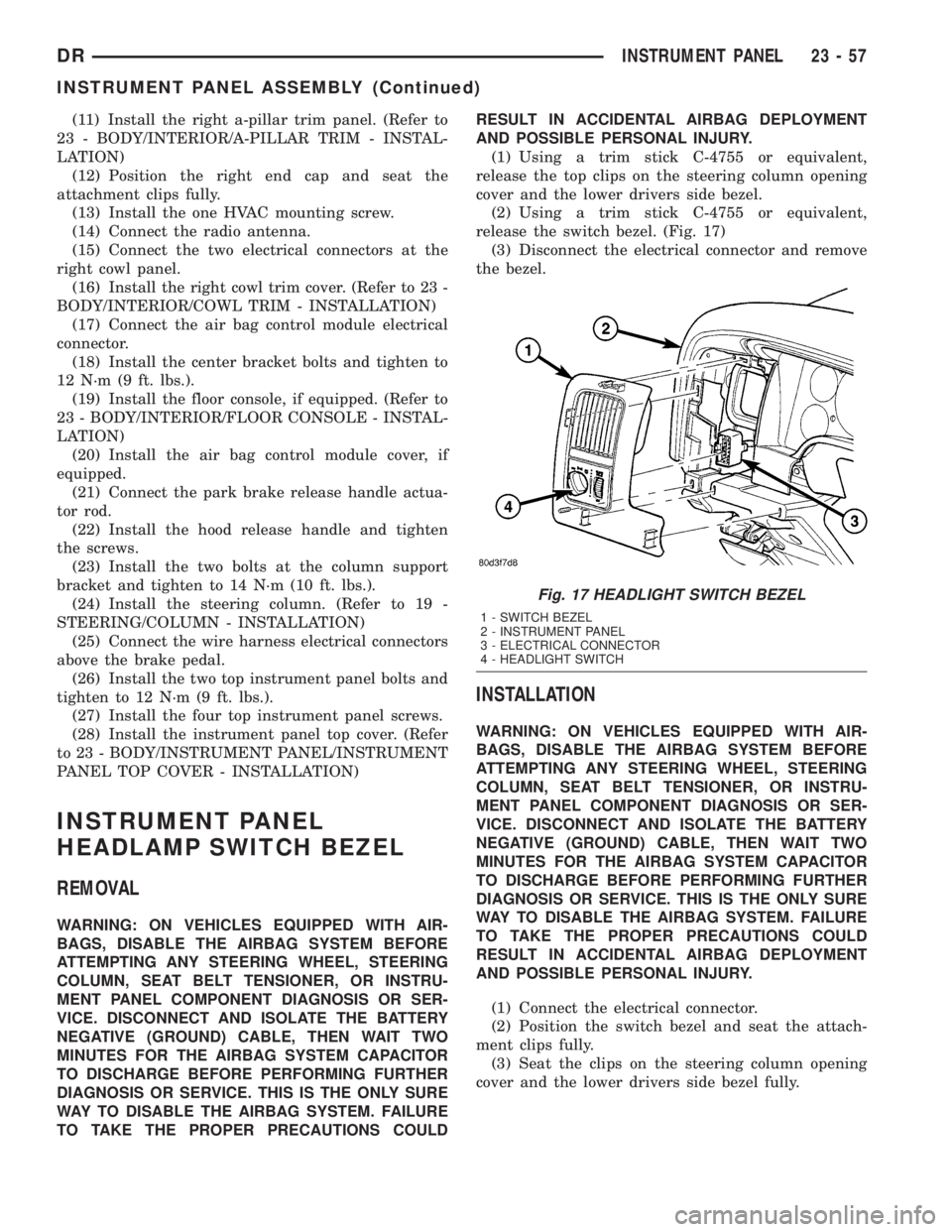
release the switch bezel. (Fig. 17)
(3) Disconnect the electrical connector and remove
the bezel.
INSTALLATION
WARNING: ON VEHICLES EQUIPPED WITH AIR-
BAGS, DISABLE THE AIRBAG SYSTEM BEFORE
ATTEMPTING ANY STEERING WHEEL, STEERING
COLUMN, SEAT BELT TENSIONER, OR INSTRU-
MENT PANEL COMPONENT DIAGNOSIS OR SER-
VICE. DISCONNECT AND ISOLATE THE BATTERY
NEGATIVE (GROUND) CABLE, THEN WAIT TWO
MINUTES FOR THE AIRBAG SYSTEM CAPACITOR
TO DISCHARGE BEFORE PERFORMING FURTHER
DIAGNOSIS OR SERVICE. THIS IS THE ONLY SURE
WAY TO DISABLE THE AIRBAG SYSTEM. FAILURE
TO TAKE THE PROPER PRECAUTIONS COULD
RESULT IN ACCIDENTAL AIRBAG DEPLOYMENT
AND POSSIBLE PERSONAL INJURY.
(1) Connect the electrical connector.
(2) Position the switch bezel and seat the attach-
ment clips fully.
(3) Seat the clips on the steering column opening
cover and the lower drivers side bezel fully.
Fig. 17 HEADLIGHT SWITCH BEZEL
1 - SWITCH BEZEL
2 - INSTRUMENT PANEL
3 - ELECTRICAL CONNECTOR
4 - HEADLIGHT SWITCH
DRINSTRUMENT PANEL 23 - 57
INSTRUMENT PANEL ASSEMBLY (Continued)