group 13 DODGE RAM 2003 Service Repair Manual
[x] Cancel search | Manufacturer: DODGE, Model Year: 2003, Model line: RAM, Model: DODGE RAM 2003Pages: 2895, PDF Size: 83.15 MB
Page 1 of 2895
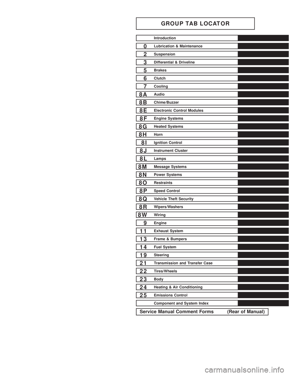
GROUP TAB LOCATOR
Introduction
0Lubrication & Maintenance
2Suspension
3Differential & Driveline
5Brakes
6Clutch
7Cooling
8AAudio
8BChime/Buzzer
8EElectronic Control Modules
8FEngine Systems
8GHeated Systems
8HHorn
8IIgnition Control
8JInstrument Cluster
8LLamps
8MMessage Systems
8NPower Systems
8ORestraints
8PSpeed Control
8QVehicle Theft Security
8RWipers/Washers
8WWiring
9Engine
11Exhaust System
13Frame & Bumpers
14Fuel System
19Steering
21Transmission and Transfer Case
22Tires/Wheels
23Body
24Heating & Air Conditioning
25Emissions Control
Component and System Index
Service Manual Comment Forms (Rear of Manual)
Page 12 of 2895
TORQUE REFERENCES
DESCRIPTION
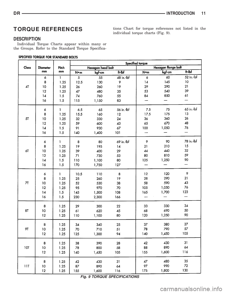
Individual Torque Charts appear within many or
the Groups. Refer to the Standard Torque Specifica-tions Chart for torque references not listed in the
individual torque charts (Fig. 9).
Fig. 9 TORQUE SPECIFICATIONS
DRINTRODUCTION 11
Page 17 of 2895
must alwaysbe a minimum of 44 percent, year-
round in all climates. If percentage is lower, engine
parts may be eroded by cavitation. Maximum protec-
tion against freezing is provided with a 68 percent
antifreeze concentration, which prevents freezing
down to -67.7ÉC (-90ÉF). A higher percentage will
freeze at a warmer temperature. Also, a higher per-
centage of antifreeze can cause the engine to over-
heat because specific heat of antifreeze is lower than
that of water.
CAUTION: Richer antifreeze mixtures cannot be
measured with normal field equipment and can
cause problems associated with 100 percent ethyl-
ene-glycol.
COOLANT SELECTION AND ADDITIVES
NOTE: Refer to the vehicle's coolant bottle to iden-
tify HOAT or Non-HOAT coolant. Non-HOAT coolant
is green in color.
The use of aluminum cylinder blocks, cylinder
heads and water pumps requires special corrosion
protection. Only MopartAntifreeze/Coolant, 5
Year/100,000 Mile Formula (glycol base coolant with
corrosion inhibitors called HOAT, for Hybrid Organic
Additive Technology) is recommended. This coolant
offers the best engine cooling without corrosion when
mixed with 50% distilled water to obtain to obtain a
freeze point of -37ÉC (-35ÉF). If it loses color or
becomes contaminated, drain, flush, and replace with
fresh properly mixed coolant solution.
CAUTION: Do not use coolant additives that are
claimed to improve engine cooling.
DESCRIPTION - TRANSFER CASE - NV241
GENII
Recommended lubricant for the NV241 GENII
transfer case is MopartATF +4, Automatic Trans-
mission Fluid.
DESCRIPTION - TRANSFER CASE - NV271
Recommended lubricant for the NV271 transfer
case is MopartATF +4, Automatic Transmission
Fluid.
DESCRIPTION - TRANSFER CASE - NV243
Recommended lubricant for the NV243 transfer case
is MopartATF +4, Automatic Transmission Fluid.
DESCRIPTION - TRANSFER CASE - NV273
Recommended lubricant for the NV273 transfer case
is MopartATF +4, Automatic Transmission Fluid.
DESCRIPTION - AXLE
NOTE: DaimlerChrysler recommends using MoparT
lubricants or lubricants of equal quality.
FRONT AXLE
²C205F - MopartGear Lubricant 75W-90
²9 1/4 AA - MopartSynthetic Gear Lubricant
75W-90
REAR AXLE
²9 1/4 - MopartSynthetic Gear Lubricant 75W-140
²10 1/2 AA - MopartSynthetic Gear Lubricant
75W-90
²11 1/2 AA - MopartSynthetic Gear Lubricant
75W-90
NOTE: Trac-LokTdifferentials require Limited Slip
Additive in the lubricant. Trac-RiteŸ differentials
DO NOT require Limited Slip Additive.
DESCRIPTION - MANUAL TRANSMISSION
NOTE: DaimlerChrysler recommends using MoparT
lubricants or lubricants of equal quality.
²
NV3500 - MopartManual Transmission Lubricant
²NV4500 - MopartSynthetic 75W85 Manual
Transmission Lubricant
²NV5600 - MopartManual Transmission Lubri-
cant
DESCRIPTION - AUTOMATIC TRANSMISSION
FLUID
NOTE: Refer to Service Procedures in this group for
fluid level checking procedures.
MopartATF +4, Automatic Transmission Fluid is
the recommended fluid for DaimlerChrysler auto-
matic transmissions.
Dexron II fluid IS NOT recommended. Clutch
chatter can result from the use of improper
fluid.
MopartATF +4, Automatic Transmission Fluid
when new is red in color. The ATF is dyed red so it
can be identified from other fluids used in the vehicle
such as engine oil or antifreeze. The red color is not
permanent and is not an indicator of fluid condition.
As the vehicle is driven, the ATF will begin to look
darker in color and may eventually become brown.
This is normal.ATF+4 also has a unique odor that
may change with age. Consequently, odor and color
cannot be used to indicate the fluid condition or the
need for a fluid change.
0 - 4 LUBRICATION & MAINTENANCEDR
FLUID TYPES (Continued)
Page 299 of 2895
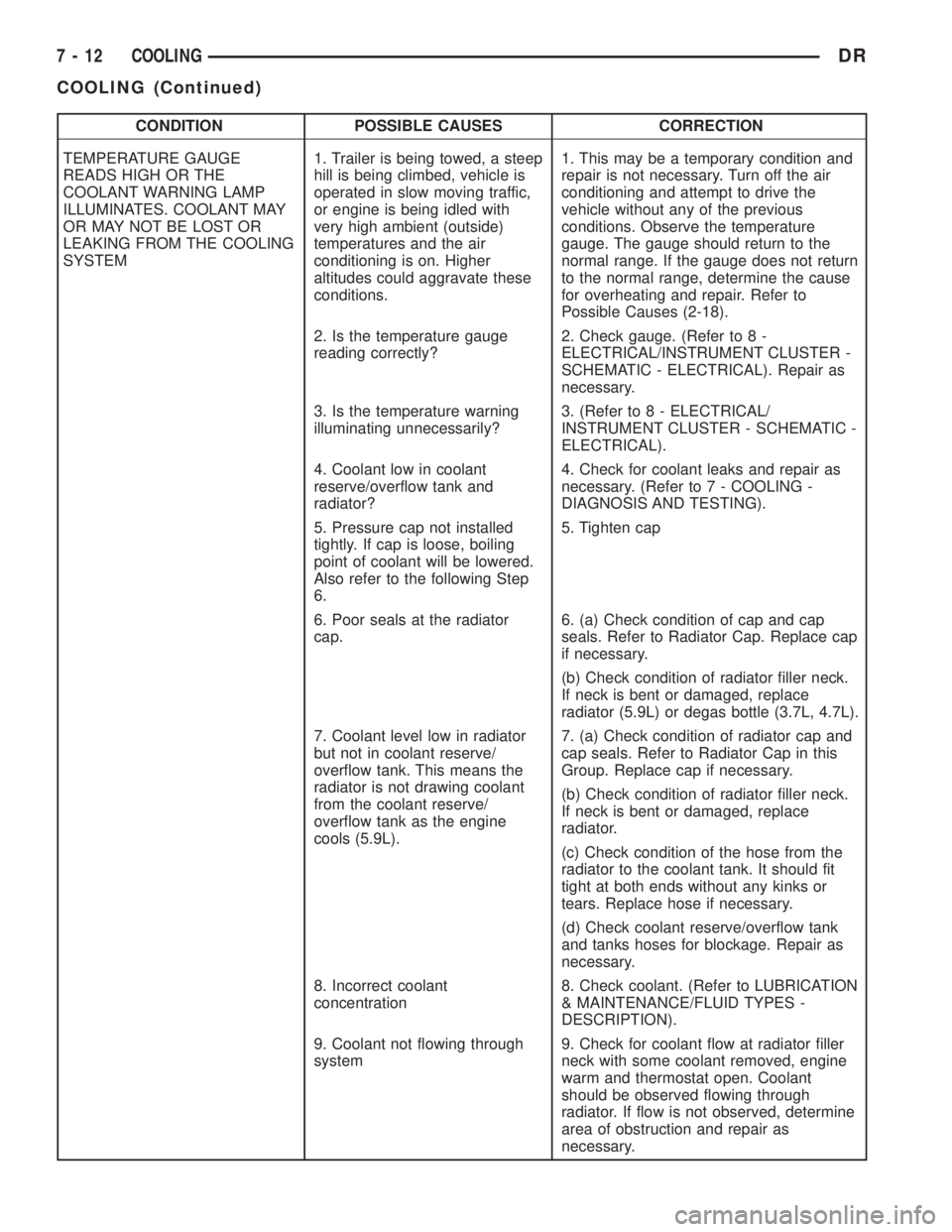
CONDITION POSSIBLE CAUSES CORRECTION
TEMPERATURE GAUGE
READS HIGH OR THE
COOLANT WARNING LAMP
ILLUMINATES. COOLANT MAY
OR MAY NOT BE LOST OR
LEAKING FROM THE COOLING
SYSTEM1. Trailer is being towed, a steep
hill is being climbed, vehicle is
operated in slow moving traffic,
or engine is being idled with
very high ambient (outside)
temperatures and the air
conditioning is on. Higher
altitudes could aggravate these
conditions.1. This may be a temporary condition and
repair is not necessary. Turn off the air
conditioning and attempt to drive the
vehicle without any of the previous
conditions. Observe the temperature
gauge. The gauge should return to the
normal range. If the gauge does not return
to the normal range, determine the cause
for overheating and repair. Refer to
Possible Causes (2-18).
2. Is the temperature gauge
reading correctly?2. Check gauge. (Refer to 8 -
ELECTRICAL/INSTRUMENT CLUSTER -
SCHEMATIC - ELECTRICAL). Repair as
necessary.
3. Is the temperature warning
illuminating unnecessarily?3. (Refer to 8 - ELECTRICAL/
INSTRUMENT CLUSTER - SCHEMATIC -
ELECTRICAL).
4. Coolant low in coolant
reserve/overflow tank and
radiator?4. Check for coolant leaks and repair as
necessary. (Refer to 7 - COOLING -
DIAGNOSIS AND TESTING).
5. Pressure cap not installed
tightly. If cap is loose, boiling
point of coolant will be lowered.
Also refer to the following Step
6.5. Tighten cap
6. Poor seals at the radiator
cap.6. (a) Check condition of cap and cap
seals. Refer to Radiator Cap. Replace cap
if necessary.
(b) Check condition of radiator filler neck.
If neck is bent or damaged, replace
radiator (5.9L) or degas bottle (3.7L, 4.7L).
7. Coolant level low in radiator
but not in coolant reserve/
overflow tank. This means the
radiator is not drawing coolant
from the coolant reserve/
overflow tank as the engine
cools (5.9L).7. (a) Check condition of radiator cap and
cap seals. Refer to Radiator Cap in this
Group. Replace cap if necessary.
(b) Check condition of radiator filler neck.
If neck is bent or damaged, replace
radiator.
(c) Check condition of the hose from the
radiator to the coolant tank. It should fit
tight at both ends without any kinks or
tears. Replace hose if necessary.
(d) Check coolant reserve/overflow tank
and tanks hoses for blockage. Repair as
necessary.
8. Incorrect coolant
concentration8. Check coolant. (Refer to LUBRICATION
& MAINTENANCE/FLUID TYPES -
DESCRIPTION).
9. Coolant not flowing through
system9. Check for coolant flow at radiator filler
neck with some coolant removed, engine
warm and thermostat open. Coolant
should be observed flowing through
radiator. If flow is not observed, determine
area of obstruction and repair as
necessary.
7 - 12 COOLINGDR
COOLING (Continued)
Page 317 of 2895
CONDITION POSSIBLE CAUSES CORRECTION
NOISE
(Objectionable squeal, squeak, or
rumble is heard or felt while drive
belt is in operation)1. Incorrect belt tension 1. Inspect/Replace tensioner if
necessary
2. Bearing noise 2. Locate and repair
3. Belt misalignment 3. Align belt/pulley(s)
4. Belt to pulley mismatch 4. Install correct belt
5. Driven component induced
vibration5. Locate defective driven
component and repair
TENSION SHEETING FABRIC
FAILURE
(Woven fabric on outside,
circumference of belt has cracked or
separated from body of belt)1. Tension sheeting contacting
stationary object1. Correct rubbing condition
2. Excessive heat causing woven
fabric to age2. Replace belt
3. Tension sheeting splice has
fractured3. Replace belt
CORD EDGE FAILURE
(Tensile member exposed at edges
of belt or separated from belt body)1. Incorrect belt tension 1. Inspect/Replace tensioner if
necessary
2. Belt contacting stationary object 2. Replace belt
3. Pulley(s) out of tolerance 3. Replace pulley
4. Insufficient adhesion between
tensile member and rubber matrix4. Replace belt
REMOVAL
NOTE: The belt routing schematics are published
from the latest information available at the time of
publication. If anything differs between these sche-
matics and the Belt Routing Label, use the sche-
matics on Belt Routing Label.This label is located in
the engine compartment.
CAUTION: Do not attempt to check belt tension with
a belt tension gauge on vehicles equipped with an
automatic belt tensioner. Refer to Automatic Belt
Tensioner in this group.
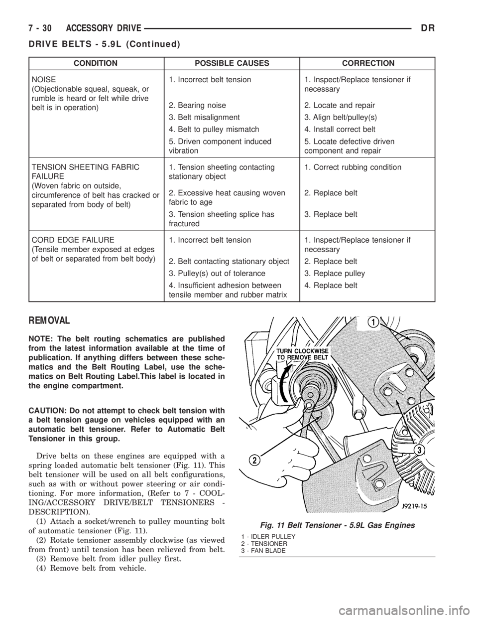
Drive belts on these engines are equipped with a
spring loaded automatic belt tensioner (Fig. 11). This
belt tensioner will be used on all belt configurations,
such as with or without power steering or air condi-
tioning. For more information, (Refer to 7 - COOL-
ING/ACCESSORY DRIVE/BELT TENSIONERS -
DESCRIPTION).
(1) Attach a socket/wrench to pulley mounting bolt
of automatic tensioner (Fig. 11).
(2) Rotate tensioner assembly clockwise (as viewed
from front) until tension has been relieved from belt.
(3) Remove belt from idler pulley first.
(4) Remove belt from vehicle.
Fig. 11 Belt Tensioner - 5.9L Gas Engines
1 - IDLER PULLEY
2 - TENSIONER
3 - FAN BLADE
7 - 30 ACCESSORY DRIVEDR
DRIVE BELTS - 5.9L (Continued)
Page 321 of 2895
NOTE: The engine speed sensor face is very close
to the accessory drive belt. Inspect engine speed
sensor and wire harness for damage when acces-
sory drive belt has been replaced due to failure or
abnormal conditions.
REMOVAL
CAUTION: Do not attempt to check belt tension with
a belt tension gauge on vehicles equipped with an
automatic belt tensioner. Refer to Automatic Belt
Tensioner in this group.
NOTE: The belt routing schematics are published
from the latest information available at the time of
publication. If anything differs between these sche-
matics and the Belt Routing Label, use the sche-
matics on Belt Routing Label.This label is located in
the engine compartment.
Drive belts on diesel engines are equipped with a
spring loaded automatic belt tensioner.displays the
tensioner for vehicles without air conditioning.
This belt tensioner will be used on all belt config-
urations, such as with or without air conditioning.
For more information, (Refer to 7 - COOLING/AC-
CESSORY DRIVE/BELT TENSIONERS - DESCRIP-
TION).
(1) A 1/2 inch square hole is provided in the auto-
matic belt tensioner. Attach a 1/2 inch drive-long
handle ratchet to this hole.
(2) Rotate ratchet and tensioner assembly clock-
wise (as viewed from front) until tension has been
relieved from belt.
(3) Remove belt from water pump pulley first.
(4) Remove belt from vehicle.
INSTALLATION
CAUTION: When installing the accessory drive belt,
the belt must be routed correctly. If not, engine mayoverheat due to water pump rotating in wrong
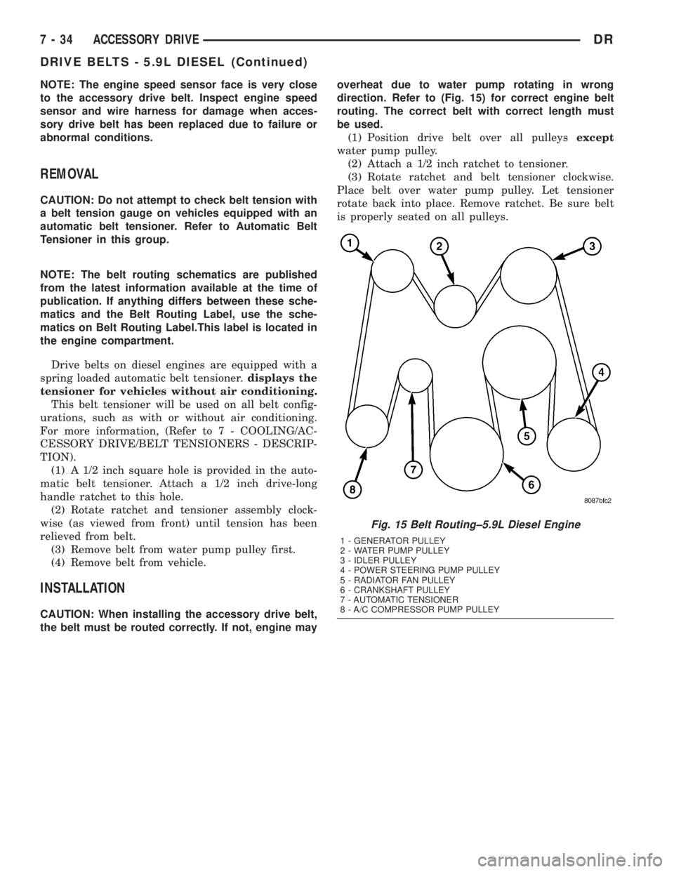
direction. Refer to (Fig. 15) for correct engine belt
routing. The correct belt with correct length must
be used.
(1) Position drive belt over all pulleysexcept
water pump pulley.
(2) Attach a 1/2 inch ratchet to tensioner.
(3) Rotate ratchet and belt tensioner clockwise.
Place belt over water pump pulley. Let tensioner
rotate back into place. Remove ratchet. Be sure belt
is properly seated on all pulleys.
Fig. 15 Belt Routing±5.9L Diesel Engine
1 - GENERATOR PULLEY
2 - WATER PUMP PULLEY
3 - IDLER PULLEY
4 - POWER STEERING PUMP PULLEY
5 - RADIATOR FAN PULLEY
6 - CRANKSHAFT PULLEY
7 - AUTOMATIC TENSIONER
8 - A/C COMPRESSOR PUMP PULLEY
7 - 34 ACCESSORY DRIVEDR
DRIVE BELTS - 5.9L DIESEL (Continued)
Page 326 of 2895
The air space also acts as sort of a spring that pro-
vides constant system pressurization in conjunction
with the radiator cap on top of the container. By
returning coolant to the pump side of the inlet ther-
mostat, the degas container also supplies greater
pressure to the coolant pump, providing for enhanced
coolant flow at high engine speeds.
The degas container also provides a convenient and
safe method for checking the coolant level with out
removing the radiator pressure cap. The degas con-
tainer does not require a separate overflow container
since it was designed with enough volume to provide
a coolant reserve and also protect for any after-boil
conditions.
REMOVAL
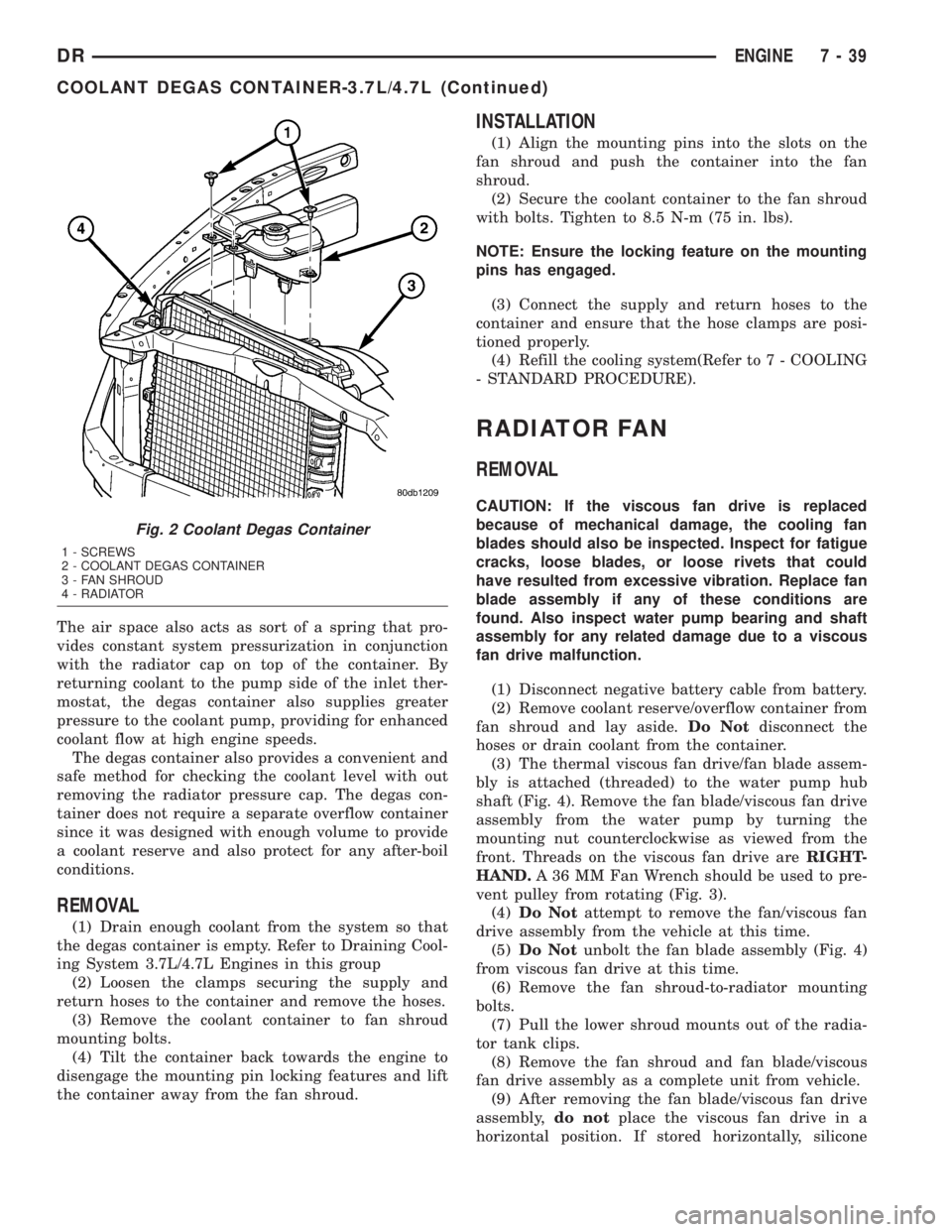
(1) Drain enough coolant from the system so that
the degas container is empty. Refer to Draining Cool-
ing System 3.7L/4.7L Engines in this group
(2) Loosen the clamps securing the supply and
return hoses to the container and remove the hoses.
(3) Remove the coolant container to fan shroud
mounting bolts.
(4) Tilt the container back towards the engine to
disengage the mounting pin locking features and lift
the container away from the fan shroud.
INSTALLATION
(1) Align the mounting pins into the slots on the
fan shroud and push the container into the fan
shroud.
(2) Secure the coolant container to the fan shroud
with bolts. Tighten to 8.5 N-m (75 in. lbs).
NOTE: Ensure the locking feature on the mounting
pins has engaged.
(3) Connect the supply and return hoses to the
container and ensure that the hose clamps are posi-
tioned properly.
(4) Refill the cooling system(Refer to 7 - COOLING
- STANDARD PROCEDURE).
RADIATOR FAN
REMOVAL
CAUTION: If the viscous fan drive is replaced
because of mechanical damage, the cooling fan
blades should also be inspected. Inspect for fatigue
cracks, loose blades, or loose rivets that could
have resulted from excessive vibration. Replace fan
blade assembly if any of these conditions are
found. Also inspect water pump bearing and shaft
assembly for any related damage due to a viscous
fan drive malfunction.
(1) Disconnect negative battery cable from battery.
(2) Remove coolant reserve/overflow container from
fan shroud and lay aside.Do Notdisconnect the
hoses or drain coolant from the container.
(3) The thermal viscous fan drive/fan blade assem-
bly is attached (threaded) to the water pump hub
shaft (Fig. 4). Remove the fan blade/viscous fan drive
assembly from the water pump by turning the
mounting nut counterclockwise as viewed from the
front. Threads on the viscous fan drive areRIGHT-
HAND.A 36 MM Fan Wrench should be used to pre-
vent pulley from rotating (Fig. 3).
(4)Do Notattempt to remove the fan/viscous fan
drive assembly from the vehicle at this time.
(5)Do Notunbolt the fan blade assembly (Fig. 4)
from viscous fan drive at this time.
(6) Remove the fan shroud-to-radiator mounting
bolts.
(7) Pull the lower shroud mounts out of the radia-
tor tank clips.
(8) Remove the fan shroud and fan blade/viscous
fan drive assembly as a complete unit from vehicle.
(9) After removing the fan blade/viscous fan drive
assembly,do notplace the viscous fan drive in a
horizontal position. If stored horizontally, silicone
Fig. 2 Coolant Degas Container
1 - SCREWS
2 - COOLANT DEGAS CONTAINER
3 - FAN SHROUD
4 - RADIATOR
DRENGINE 7 - 39
COOLANT DEGAS CONTAINER-3.7L/4.7L (Continued)
Page 333 of 2895
(2) Disconnect the electrical connector from the
sensor.
(3) Remove the sensor from the cylinder head.
5.9L V-8 Gas
WARNING: HOT, PRESSURIZED COOLANT CAN
CAUSE INJURY BY SCALDING. COOLING SYSTEM
MUST BE PARTIALLY DRAINED BEFORE REMOV-
ING THE COOLANT TEMPERATURE SENSOR.
REFER TO GROUP 7, COOLING.
(1) Partially drain the cooling system. Refer to 7,
COOLING.
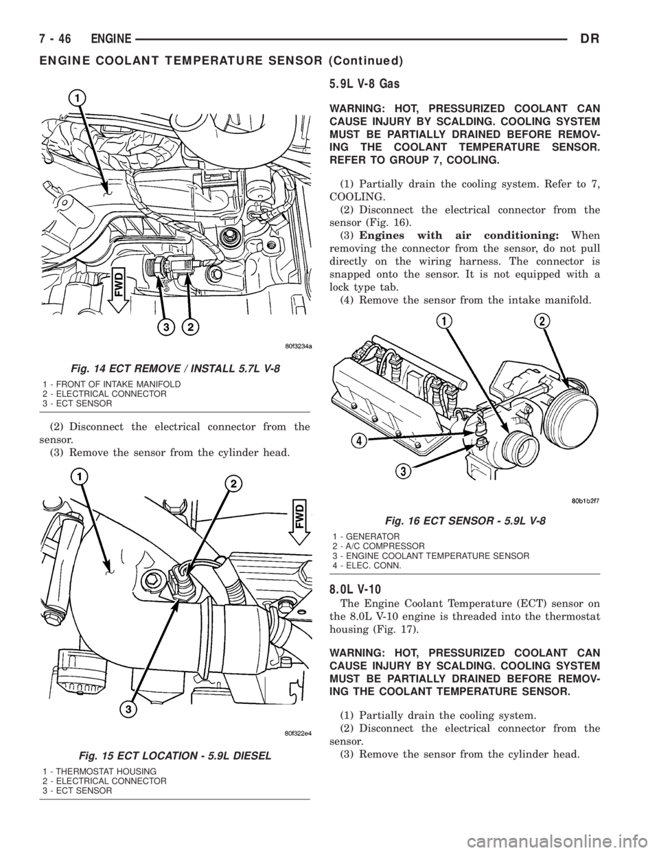
(2) Disconnect the electrical connector from the
sensor (Fig. 16).
(3)Engines with air conditioning:When
removing the connector from the sensor, do not pull
directly on the wiring harness. The connector is
snapped onto the sensor. It is not equipped with a
lock type tab.
(4) Remove the sensor from the intake manifold.
8.0L V-10
The Engine Coolant Temperature (ECT) sensor on
the 8.0L V-10 engine is threaded into the thermostat
housing (Fig. 17).
WARNING: HOT, PRESSURIZED COOLANT CAN
CAUSE INJURY BY SCALDING. COOLING SYSTEM
MUST BE PARTIALLY DRAINED BEFORE REMOV-
ING THE COOLANT TEMPERATURE SENSOR.
(1) Partially drain the cooling system.
(2) Disconnect the electrical connector from the
sensor.
(3) Remove the sensor from the cylinder head.
Fig. 14 ECT REMOVE / INSTALL 5.7L V-8
1 - FRONT OF INTAKE MANIFOLD
2 - ELECTRICAL CONNECTOR
3 - ECT SENSOR
Fig. 15 ECT LOCATION - 5.9L DIESEL
1 - THERMOSTAT HOUSING
2 - ELECTRICAL CONNECTOR
3 - ECT SENSOR
Fig. 16 ECT SENSOR - 5.9L V-8
1 - GENERATOR
2 - A/C COMPRESSOR
3 - ENGINE COOLANT TEMPERATURE SENSOR
4 - ELEC. CONN.
7 - 46 ENGINEDR
ENGINE COOLANT TEMPERATURE SENSOR (Continued)
Page 335 of 2895
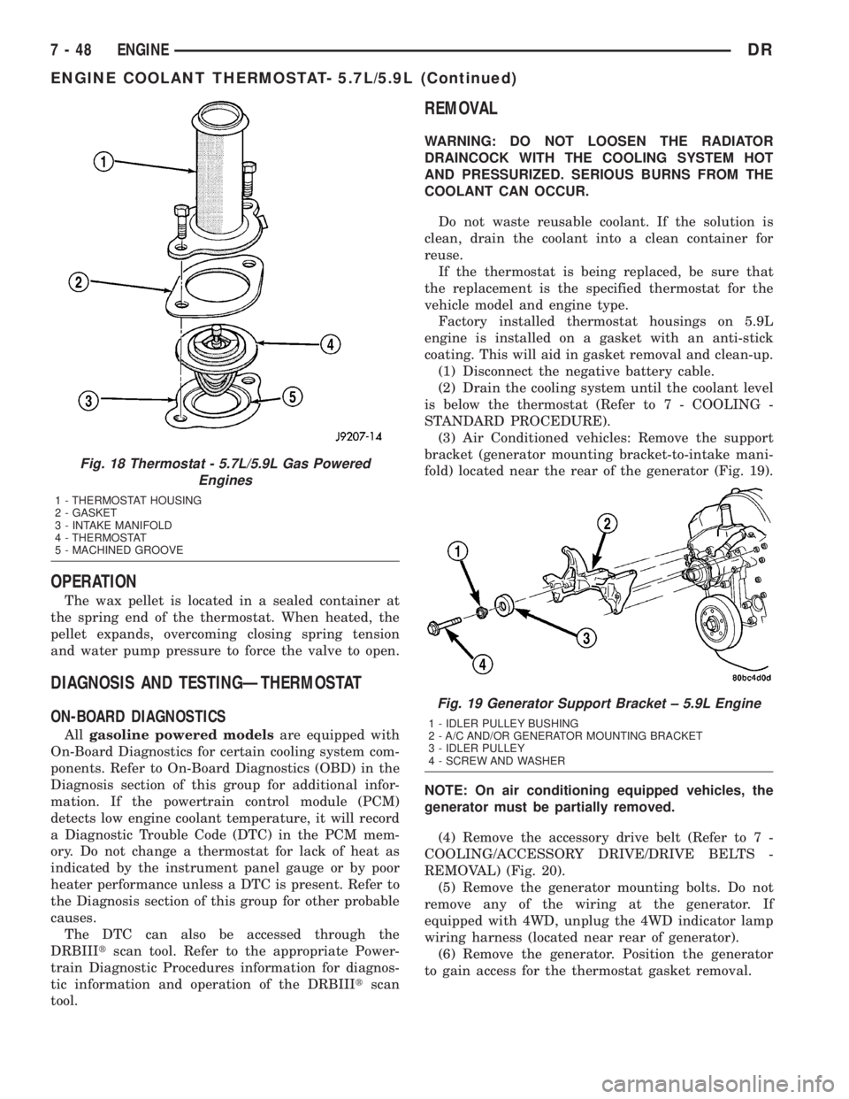
OPERATION
The wax pellet is located in a sealed container at
the spring end of the thermostat. When heated, the
pellet expands, overcoming closing spring tension
and water pump pressure to force the valve to open.
DIAGNOSIS AND TESTINGÐTHERMOSTAT
ON-BOARD DIAGNOSTICS
Allgasoline powered modelsare equipped with
On-Board Diagnostics for certain cooling system com-
ponents. Refer to On-Board Diagnostics (OBD) in the
Diagnosis section of this group for additional infor-
mation. If the powertrain control module (PCM)
detects low engine coolant temperature, it will record
a Diagnostic Trouble Code (DTC) in the PCM mem-
ory. Do not change a thermostat for lack of heat as
indicated by the instrument panel gauge or by poor
heater performance unless a DTC is present. Refer to
the Diagnosis section of this group for other probable
causes.
The DTC can also be accessed through the
DRBIIItscan tool. Refer to the appropriate Power-
train Diagnostic Procedures information for diagnos-
tic information and operation of the DRBIIItscan
tool.
REMOVAL
WARNING: DO NOT LOOSEN THE RADIATOR
DRAINCOCK WITH THE COOLING SYSTEM HOT
AND PRESSURIZED. SERIOUS BURNS FROM THE
COOLANT CAN OCCUR.
Do not waste reusable coolant. If the solution is
clean, drain the coolant into a clean container for
reuse.
If the thermostat is being replaced, be sure that
the replacement is the specified thermostat for the
vehicle model and engine type.
Factory installed thermostat housings on 5.9L
engine is installed on a gasket with an anti-stick
coating. This will aid in gasket removal and clean-up.
(1) Disconnect the negative battery cable.
(2) Drain the cooling system until the coolant level
is below the thermostat (Refer to 7 - COOLING -
STANDARD PROCEDURE).
(3) Air Conditioned vehicles: Remove the support
bracket (generator mounting bracket-to-intake mani-
fold) located near the rear of the generator (Fig. 19).
NOTE: On air conditioning equipped vehicles, the
generator must be partially removed.
(4) Remove the accessory drive belt (Refer to 7 -
COOLING/ACCESSORY DRIVE/DRIVE BELTS -
REMOVAL) (Fig. 20).
(5) Remove the generator mounting bolts. Do not
remove any of the wiring at the generator. If
equipped with 4WD, unplug the 4WD indicator lamp
wiring harness (located near rear of generator).
(6) Remove the generator. Position the generator
to gain access for the thermostat gasket removal.
Fig. 18 Thermostat - 5.7L/5.9L Gas Powered
Engines
1 - THERMOSTAT HOUSING
2 - GASKET
3 - INTAKE MANIFOLD
4 - THERMOSTAT
5 - MACHINED GROOVE
Fig. 19 Generator Support Bracket ± 5.9L Engine
1 - IDLER PULLEY BUSHING
2 - A/C AND/OR GENERATOR MOUNTING BRACKET
3 - IDLER PULLEY
4 - SCREW AND WASHER
7 - 48 ENGINEDR
ENGINE COOLANT THERMOSTAT- 5.7L/5.9L (Continued)
Page 338 of 2895
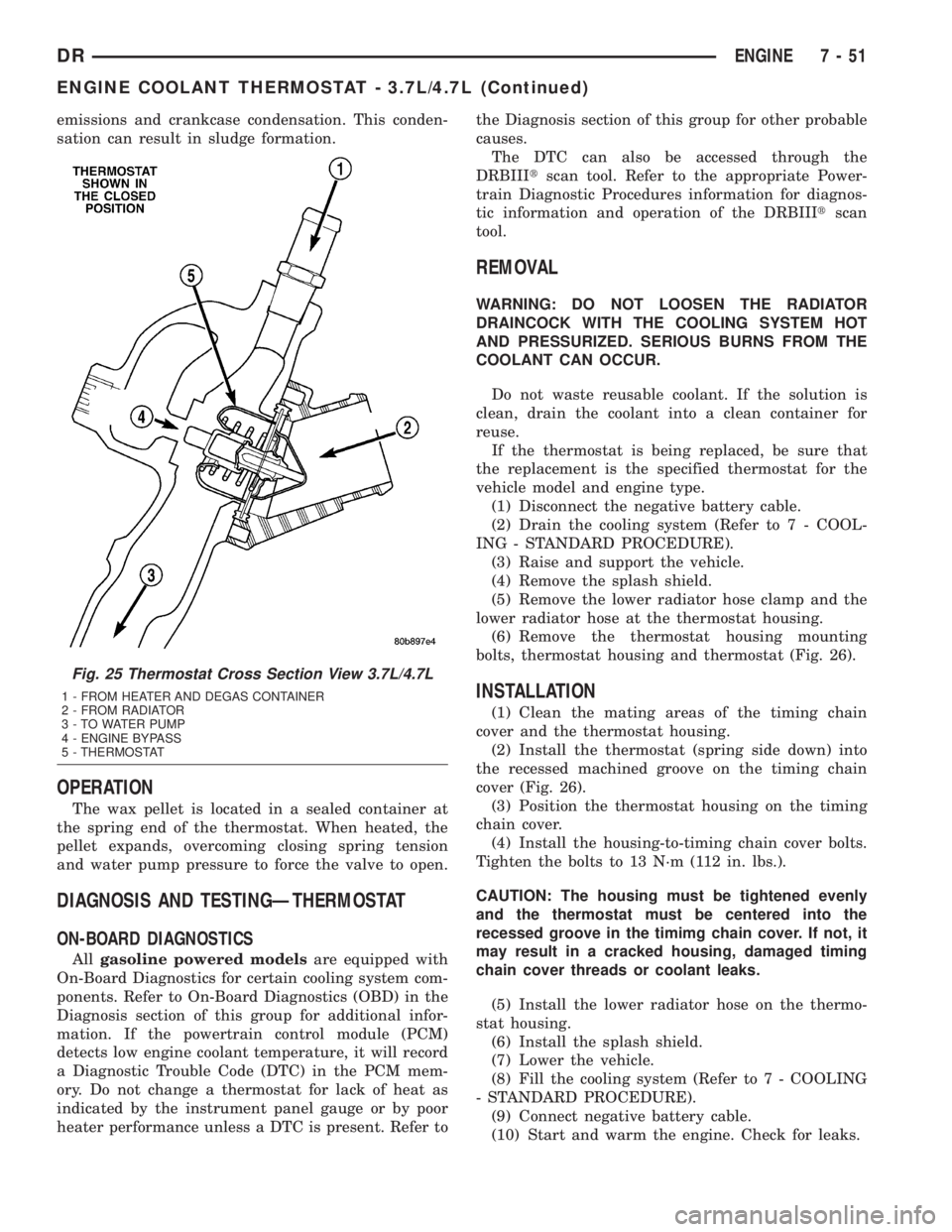
emissions and crankcase condensation. This conden-
sation can result in sludge formation.
OPERATION
The wax pellet is located in a sealed container at
the spring end of the thermostat. When heated, the
pellet expands, overcoming closing spring tension
and water pump pressure to force the valve to open.
DIAGNOSIS AND TESTINGÐTHERMOSTAT
ON-BOARD DIAGNOSTICS
Allgasoline powered modelsare equipped with
On-Board Diagnostics for certain cooling system com-
ponents. Refer to On-Board Diagnostics (OBD) in the
Diagnosis section of this group for additional infor-
mation. If the powertrain control module (PCM)
detects low engine coolant temperature, it will record
a Diagnostic Trouble Code (DTC) in the PCM mem-
ory. Do not change a thermostat for lack of heat as
indicated by the instrument panel gauge or by poor
heater performance unless a DTC is present. Refer tothe Diagnosis section of this group for other probable
causes.
The DTC can also be accessed through the
DRBIIItscan tool. Refer to the appropriate Power-
train Diagnostic Procedures information for diagnos-
tic information and operation of the DRBIIItscan
tool.
REMOVAL
WARNING: DO NOT LOOSEN THE RADIATOR
DRAINCOCK WITH THE COOLING SYSTEM HOT
AND PRESSURIZED. SERIOUS BURNS FROM THE
COOLANT CAN OCCUR.
Do not waste reusable coolant. If the solution is
clean, drain the coolant into a clean container for
reuse.
If the thermostat is being replaced, be sure that
the replacement is the specified thermostat for the
vehicle model and engine type.
(1) Disconnect the negative battery cable.
(2) Drain the cooling system (Refer to 7 - COOL-
ING - STANDARD PROCEDURE).
(3) Raise and support the vehicle.
(4) Remove the splash shield.
(5) Remove the lower radiator hose clamp and the
lower radiator hose at the thermostat housing.
(6) Remove the thermostat housing mounting
bolts, thermostat housing and thermostat (Fig. 26).
INSTALLATION
(1) Clean the mating areas of the timing chain
cover and the thermostat housing.
(2) Install the thermostat (spring side down) into
the recessed machined groove on the timing chain
cover (Fig. 26).
(3) Position the thermostat housing on the timing
chain cover.
(4) Install the housing-to-timing chain cover bolts.
Tighten the bolts to 13 N´m (112 in. lbs.).
CAUTION: The housing must be tightened evenly
and the thermostat must be centered into the
recessed groove in the timimg chain cover. If not, it
may result in a cracked housing, damaged timing
chain cover threads or coolant leaks.
(5) Install the lower radiator hose on the thermo-
stat housing.
(6) Install the splash shield.
(7) Lower the vehicle.
(8) Fill the cooling system (Refer to 7 - COOLING
- STANDARD PROCEDURE).
(9) Connect negative battery cable.
(10) Start and warm the engine. Check for leaks.
Fig. 25 Thermostat Cross Section View 3.7L/4.7L
1 - FROM HEATER AND DEGAS CONTAINER
2 - FROM RADIATOR
3 - TO WATER PUMP
4 - ENGINE BYPASS
5 - THERMOSTAT
DRENGINE 7 - 51
ENGINE COOLANT THERMOSTAT - 3.7L/4.7L (Continued)