light DODGE RAM 2003 Service Repair Manual
[x] Cancel search | Manufacturer: DODGE, Model Year: 2003, Model line: RAM, Model: DODGE RAM 2003Pages: 2895, PDF Size: 83.15 MB
Page 4 of 2895
POSITION INTERPRETATION CODE = DESCRIPTION
8 Engine K = 3.7L 6 cyl. MPI Gasoline
N = 4.7L 8 cyl. MPI Gasoline
D = 5.7L 8 cyl. SMPI Gasoline
6 = 5.9L 6 cyl. Turbo Diesel
C = 5.9L 6 cyl. Turbo Diesel High Output
W = 8.0L 10 cyl. MPI Gasoline
Z = 5.9L 8 cyl. SMPI Gasoline Light Duty
9 Check Digit 0 through 9 or X
10 Model Year 3 = 2003
11 Plant Location S = Dodge City
G = Saltillo
J = St. Louis (North)
12 thru 17 Vehicle Build Sequence
VEHICLE EMISSION CONTROL
INFORMATION (VECI)
DESCRIPTION
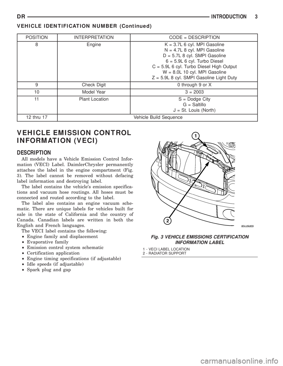
All models have a Vehicle Emission Control Infor-
mation (VECI) Label. DaimlerChrysler permanently
attaches the label in the engine compartment (Fig.
3). The label cannot be removed without defacing
label information and destroying label.
The label contains the vehicle's emission specifica-
tions and vacuum hose routings. All hoses must be
connected and routed according to the label.
The label also contains an engine vacuum sche-
matic. There are unique labels for vehicles built for
sale in the state of California and the country of
Canada. Canadian labels are written in both the
English and French languages.
The VECI label contains the following:
²Engine family and displacement
²Evaporative family
²Emission control system schematic
²Certification application
²Engine timing specifications (if adjustable)
²Idle speeds (if adjustable)
²Spark plug and gap
Fig. 3 VEHICLE EMISSIONS CERTIFICATION
INFORMATION LABEL
1 - VECI LABEL LOCATION
2 - RADIATOR SUPPORT
DRINTRODUCTION 3
VEHICLE IDENTIFICATION NUMBER (Continued)
Page 5 of 2895
BODY CODE PLATE
DESCRIPTION
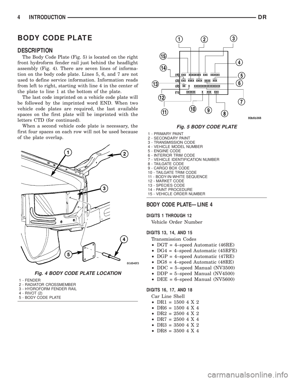
The Body Code Plate (Fig. 5) is located on the right
front hydroform fender rail just behind the headlight
assembly (Fig. 4). There are seven lines of informa-
tion on the body code plate. Lines 5, 6, and 7 are not
used to define service information. Information reads
from left to right, starting with line 4 in the center of
the plate to line 1 at the bottom of the plate.
The last code imprinted on a vehicle code plate will
be followed by the imprinted word END. When two
vehicle code plates are required, the last available
spaces on the first plate will be imprinted with the
letters CTD (for continued).
When a second vehicle code plate is necessary, the
first four spaces on each row will not be used because
of the plate overlap.
BODY CODE PLATEÐLINE 4
DIGITS 1 THROUGH 12
Vehicle Order Number
DIGITS 13, 14, AND 15
Transmission Codes
²DGT = 4±speed Automatic (46RE)
²DG4 = 4±speed Automatic (45RFE)
²DGP = 4±speed Automatic (47RE)
²DG8 = 4±speed Automatic (48RE)
²DDC = 5±speed Manual (NV3500)
²DDP = 5±speed Manual (NV4500)
²DEE = 6±speed Manual (NV5600)
DIGITS 16, 17, AND 18
Car Line Shell
²DR1=15004X2
²DR6=15004X4
²DR2=25004X2
²DR7=25004X4
²DR3=35004X2
²DR8=35004X4
Fig. 4 BODY CODE PLATE LOCATION
1 - FENDER
2 - RADIATOR CROSSMEMBER
3 - HYDROFORM FENDER RAIL
4 - RIVOT (2)
5 - BODY CODE PLATE
Fig. 5 BODY CODE PLATE
1 - PRIMARY PAINT
2 - SECONDARY PAINT
3 - TRANSMISSION CODE
4 - VEHICLE MODEL NUMBER
5 - ENGINE CODE
6 - INTERIOR TRIM CODE
7 - VEHICLE IDENTIFICATION NUMBER
8 - TAILGATE CODE
9 - CARGO BOX CODE
10 - TAILGATE TRIM CODE
11 - BODY-IN-WHITE SEQUENCE
12 - MARKET CODE
13 - SPECIES CODE
14 - PAINT PROCEDURE
15 - VEHICLE ORDER NUMBER
4 INTRODUCTIONDR
Page 7 of 2895
INTERNATIONAL VEHICLE
CONTROL & DISPLAY
SYMBOLS
DESCRIPTION - INTERNATIONAL SYMBOLS
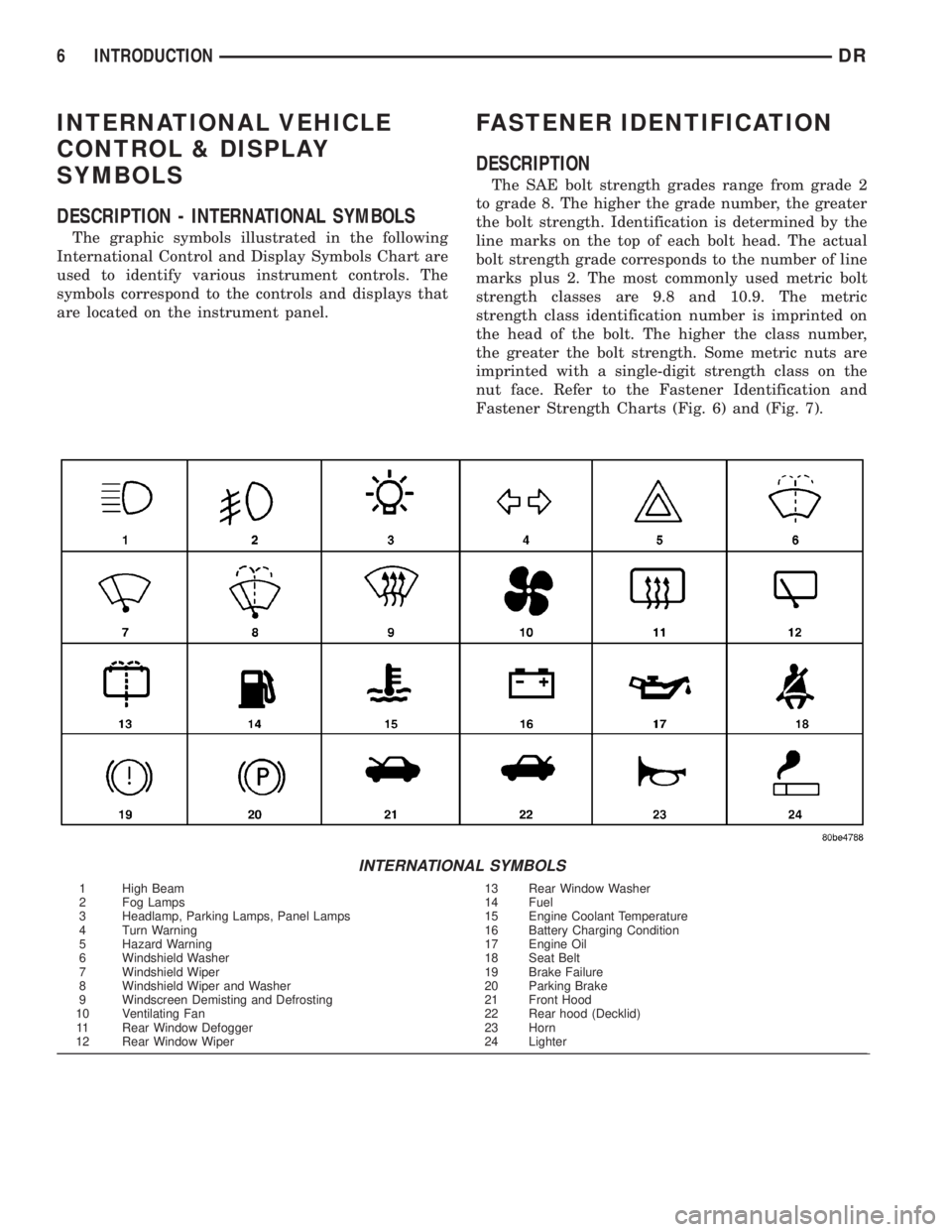
The graphic symbols illustrated in the following
International Control and Display Symbols Chart are
used to identify various instrument controls. The
symbols correspond to the controls and displays that
are located on the instrument panel.
FASTENER IDENTIFICATION
DESCRIPTION
The SAE bolt strength grades range from grade 2
to grade 8. The higher the grade number, the greater
the bolt strength. Identification is determined by the
line marks on the top of each bolt head. The actual
bolt strength grade corresponds to the number of line
marks plus 2. The most commonly used metric bolt
strength classes are 9.8 and 10.9. The metric
strength class identification number is imprinted on
the head of the bolt. The higher the class number,
the greater the bolt strength. Some metric nuts are
imprinted with a single-digit strength class on the
nut face. Refer to the Fastener Identification and
Fastener Strength Charts (Fig. 6) and (Fig. 7).
INTERNATIONAL SYMBOLS
1 High Beam 13 Rear Window Washer
2 Fog Lamps 14 Fuel
3 Headlamp, Parking Lamps, Panel Lamps 15 Engine Coolant Temperature
4 Turn Warning 16 Battery Charging Condition
5 Hazard Warning 17 Engine Oil
6 Windshield Washer 18 Seat Belt
7 Windshield Wiper 19 Brake Failure
8 Windshield Wiper and Washer 20 Parking Brake
9 Windscreen Demisting and Defrosting 21 Front Hood
10 Ventilating Fan 22 Rear hood (Decklid)
11 Rear Window Defogger 23 Horn
12 Rear Window Wiper 24 Lighter
6 INTRODUCTIONDR
Page 19 of 2895
MAINTENANCE SCHEDULES
DESCRIPTION
Maintenance Schedule Information not included in
this section, is located in the appropriate Owner's
Manual.
There are two maintenance schedules that show
therequiredservice for your vehicle.
First is ScheduleªBº. It is for vehicles that are
operated under the conditions that are listed below
and at the beginning of the schedule.
²Day or night temperatures are below 0É C (32É
F).
²Stop and go driving.
²Extensive engine idling.
²Driving in dusty conditions.
²Short trips of less than 16 km (10 miles).
²More than 50% of your driving is at sustained
high speeds during hot weather, above 32É C (90É F).
²Trailer towing.
²Taxi, police, or delivery service (commercial ser-
vice).
²Off-road or desert operation.
²If equipped for and operating with E-85
(ethanol) fuel.
NOTE: Most vehicles are operated under the condi-
tions listed for Schedule(B(.
Second is ScheduleªAº. It is for vehicles that are
not operated under any of the conditions listed under
Schedule9B9.
Use the schedule that best describes your driving
conditions. Where time and mileage are listed, follow
the interval that occurs first.
CAUTION: Failure to perform the required mainte-
nance items may result in damage to the vehicle.
At Each Stop for Fuel
²Check the engine oil level about 5 minutes after
a fully warmed engine is shut off. Checking the oil
level while the vehicle is on level ground will
improve the accuracy of the oil level reading. Add oil
only when the level is at or below the ADD or MIN
mark.
²Check the windshield washer solvent and add if
required.
Once a Month
²Check tire pressure and look for unusual wear
or damage.
²Inspect the battery and clean and tighten the
terminals as required.
²Check the fluid levels of coolant reservoir, brake
master cylinder, power steering and transmission
and add as needed.
²Check all lights and all other electrical items for
correct operation.
At Each Oil Change
²Change the engine oil filter.
²Inspect the exhaust system.
²Inspect the brake hoses.
²Inspect the CV joints (if equipped) and front sus-
pension components.
²Check the automatic transmission fluid level.
²Check the manual transmission fluid level.
²Check the coolant level, hoses, and clamps.
²Rotate the tires at each oil change interval
shown on Schedule ªAº 10 000 km (6,000 miles) or
every other interval shown on Schedule ªBº 10 000
km (6,000 miles).
Schedule ªBº
Follow schedule ªBº if you usually operate your
vehicle under one or more of the following conditions.
²Day or night temperatures are below 0É C (32É
F).
²Stop and go driving.
²Extensive engine idling.
²Driving in dusty conditions.
²Short trips of less than 16 km (10 miles).
²More than 50% of your driving is at sustained
high speeds during hot weather, above 32É C (90É F).
²Trailer towing.
²Taxi, police, or delivery service (commercial ser-
vice).
²Off-road or desert operation.
²If equipped for and operating with E-85
(ethanol) fuel.
0 - 6 LUBRICATION & MAINTENANCEDR
Page 34 of 2895
angle while adjusting caster, move one pivot bolt of
the upper control arm in or out. Then move the other
pivot bolt of the upper control arm in the opposite
direction. Install special tool 8876 between the top of
the upper control arm bracket and the upper control
arm (on 1500 series 4X2 & 4X4). Install special tool
8876 between the bottom of the upper control arm
bracket pressing the tool against the frame and the
upper control arm (on 2500/3500 series 4X2) in order
to move the upper control arm outwards for proper
adjustment with the vehicle at normal ride height
(Fig. 3).
To increase positive caster angle, move the rear
position of the upper control arm inward (toward the
engine). Move the front of the upper control arm out-
ward (away from the engine) slightly until the origi-
nal camber angle is obtained using special tool 8876
to move the upper control arm for proper adjustment.
(Fig. 3)
CAMBER
Move both pivot bolts of the upper control arm
together in or out. This will change the camber angle
significantly and little effect on the caster angle
using special tool 8876 to move the upper control
arm for proper adjustment. (Fig. 3)
After adjustment is made tighten the upper control
arm nuts to proper torque specification.
TOE ADJUSTMENT
The wheel toe position adjustment is the final
adjustment.
(1) Start the engine and turn wheels both ways
before straightening the wheels. Secure the steering
wheel with the front wheels in the straight-ahead
position.
(2) Loosen the tie rod jam nuts.
NOTE: Each front wheel should be adjusted for
one-half of the total toe position specification. This
will ensure the steering wheel will be centered
when the wheels are positioned straight-ahead.
(3) Adjust the wheel toe position by turning the
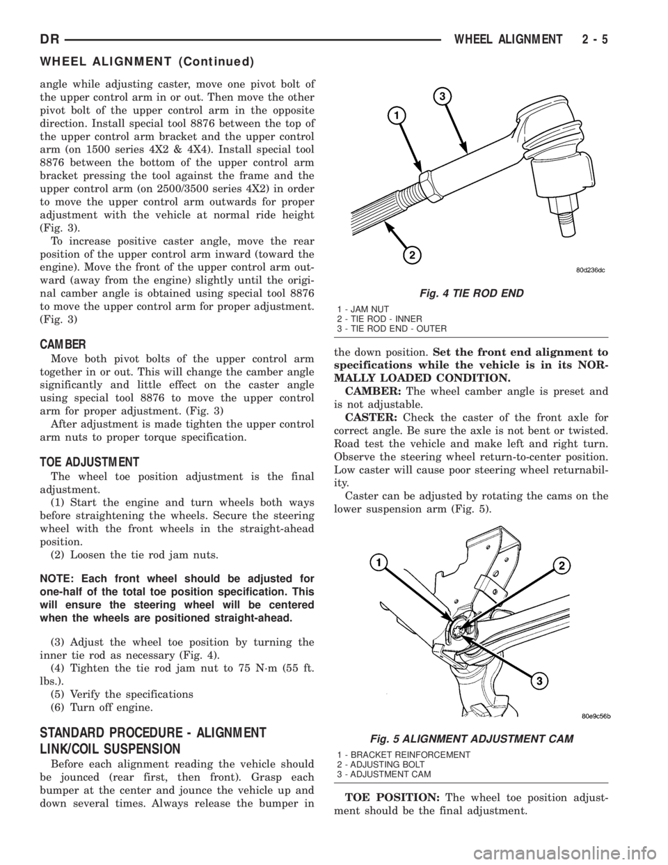
inner tie rod as necessary (Fig. 4).
(4) Tighten the tie rod jam nut to 75 N´m (55 ft.
lbs.).
(5) Verify the specifications
(6) Turn off engine.
STANDARD PROCEDURE - ALIGNMENT
LINK/COIL SUSPENSION
Before each alignment reading the vehicle should
be jounced (rear first, then front). Grasp each
bumper at the center and jounce the vehicle up and
down several times. Always release the bumper inthe down position.Set the front end alignment to
specifications while the vehicle is in its NOR-
MALLY LOADED CONDITION.
CAMBER:The wheel camber angle is preset and
is not adjustable.
CASTER:Check the caster of the front axle for
correct angle. Be sure the axle is not bent or twisted.
Road test the vehicle and make left and right turn.
Observe the steering wheel return-to-center position.
Low caster will cause poor steering wheel returnabil-
ity.
Caster can be adjusted by rotating the cams on the
lower suspension arm (Fig. 5).
TOE POSITION:The wheel toe position adjust-
ment should be the final adjustment.
Fig. 4 TIE ROD END
1 - JAM NUT
2 - TIE ROD - INNER
3 - TIE ROD END - OUTER
Fig. 5 ALIGNMENT ADJUSTMENT CAM
1 - BRACKET REINFORCEMENT
2 - ADJUSTING BOLT
3 - ADJUSTMENT CAM
DRWHEEL ALIGNMENT 2 - 5
WHEEL ALIGNMENT (Continued)
Page 85 of 2895
(9) Disengage inner C/V joint from the axle shaft
snap-ring by apply pressure with two pry bars
between the C/V housing and axle housing.
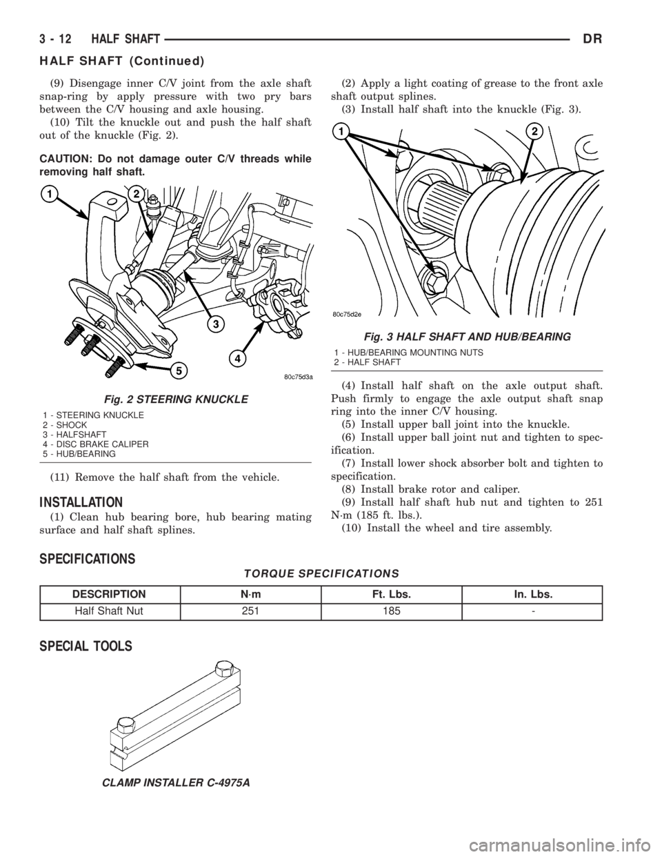
(10) Tilt the knuckle out and push the half shaft
out of the knuckle (Fig. 2).
CAUTION: Do not damage outer C/V threads while
removing half shaft.
(11) Remove the half shaft from the vehicle.
INSTALLATION
(1) Clean hub bearing bore, hub bearing mating
surface and half shaft splines.(2) Apply a light coating of grease to the front axle
shaft output splines.
(3) Install half shaft into the knuckle (Fig. 3).
(4) Install half shaft on the axle output shaft.
Push firmly to engage the axle output shaft snap
ring into the inner C/V housing.
(5) Install upper ball joint into the knuckle.
(6) Install upper ball joint nut and tighten to spec-
ification.
(7) Install lower shock absorber bolt and tighten to
specification.
(8) Install brake rotor and caliper.
(9) Install half shaft hub nut and tighten to 251
N´m (185 ft. lbs.).
(10) Install the wheel and tire assembly.
SPECIFICATIONS
TORQUE SPECIFICATIONS
DESCRIPTION N´m Ft. Lbs. In. Lbs.
Half Shaft Nut 251 185 -
SPECIAL TOOLS
Fig. 2 STEERING KNUCKLE
1 - STEERING KNUCKLE
2 - SHOCK
3 - HALFSHAFT
4 - DISC BRAKE CALIPER
5 - HUB/BEARING
Fig. 3 HALF SHAFT AND HUB/BEARING
1 - HUB/BEARING MOUNTING NUTS
2 - HALF SHAFT
CLAMP INSTALLER C-4975A
3 - 12 HALF SHAFTDR
HALF SHAFT (Continued)
Page 86 of 2895
CV JOINT-OUTER
REMOVAL
(1) Clamp shaft in a vise (with soft jaws) and sup-
port C/V joint.
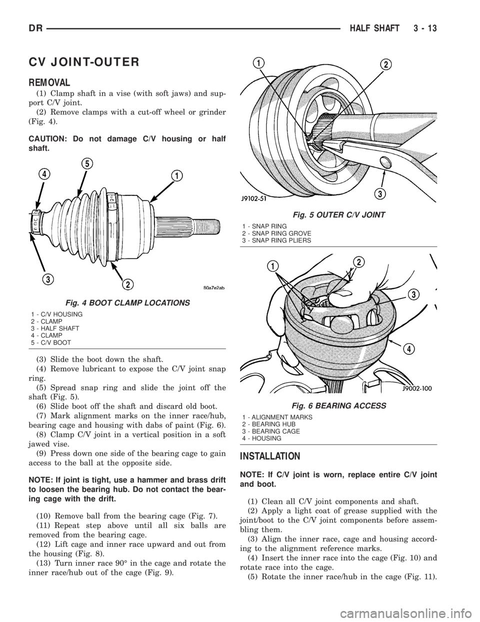
(2) Remove clamps with a cut-off wheel or grinder
(Fig. 4).
CAUTION: Do not damage C/V housing or half
shaft.
(3) Slide the boot down the shaft.
(4) Remove lubricant to expose the C/V joint snap
ring.
(5) Spread snap ring and slide the joint off the
shaft (Fig. 5).
(6) Slide boot off the shaft and discard old boot.
(7) Mark alignment marks on the inner race/hub,
bearing cage and housing with dabs of paint (Fig. 6).
(8) Clamp C/V joint in a vertical position in a soft
jawed vise.
(9) Press down one side of the bearing cage to gain
access to the ball at the opposite side.
NOTE: If joint is tight, use a hammer and brass drift
to loosen the bearing hub. Do not contact the bear-
ing cage with the drift.
(10) Remove ball from the bearing cage (Fig. 7).
(11) Repeat step above until all six balls are
removed from the bearing cage.
(12) Lift cage and inner race upward and out from
the housing (Fig. 8).
(13) Turn inner race 90É in the cage and rotate the
inner race/hub out of the cage (Fig. 9).
INSTALLATION
NOTE: If C/V joint is worn, replace entire C/V joint
and boot.
(1) Clean all C/V joint components and shaft.
(2) Apply a light coat of grease supplied with the
joint/boot to the C/V joint components before assem-
bling them.
(3) Align the inner race, cage and housing accord-
ing to the alignment reference marks.
(4) Insert the inner race into the cage (Fig. 10) and
rotate race into the cage.
(5) Rotate the inner race/hub in the cage (Fig. 11).
Fig. 4 BOOT CLAMP LOCATIONS
1 - C/V HOUSING
2 - CLAMP
3 - HALF SHAFT
4 - CLAMP
5 - C/V BOOT
Fig. 5 OUTER C/V JOINT
1 - SNAP RING
2 - SNAP RING GROVE
3 - SNAP RING PLIERS
Fig. 6 BEARING ACCESS
1 - ALIGNMENT MARKS
2 - BEARING HUB
3 - BEARING CAGE
4 - HOUSING
DRHALF SHAFT 3 - 13
Page 92 of 2895
tial bearing noise is also constant and varies only
with vehicle speed.
Axle shaft bearings produce noise and vibration
when worn or damaged. The noise generally changes
when the bearings are loaded. Road test the vehicle.
Turn the vehicle sharply to the left and to the right.
This will load the bearings and change the noise
level. Where axle bearing damage is slight, the noise
is usually not noticeable at speeds above 30 mph.
LOW SPEED KNOCK
Low speed knock is generally caused by a worn
U-joint or by worn side-gear thrust washers. A worn
pinion shaft bore will also cause low speed knock.
VIBRATION
Vibration at the rear of the vehicle is usually
caused by:
²Damaged drive shaft.
²Missing drive shaft balance weight(s).
²Worn or out of balance wheels.
²Loose wheel lug nuts.
²Worn U-joint(s).
²Loose/broken springs.
²Damaged axle shaft bearing(s).
²Loose pinion gear nut.
²Excessive pinion yoke run out.
²Bent axle shaft(s).Check for loose or damaged front end components
or engine/transmission mounts. These components
can contribute to what appears to be a rear end
vibration. Do not overlook engine accessories, brack-
ets and drive belts.
All driveline components should be examined
before starting any repair.
(Refer to 22 - TIRES/WHEELS - DIAGNOSIS AND
TESTING)
DRIVELINE SNAP
A snap or clunk noise when the vehicle is shifted
into gear (or the clutch engaged) can be caused by:
²High engine idle speed.
²Transmission shift operation.
²Loose engine/transmission/transfer case mounts.
²Worn U-joints.
²Loose spring mounts.
²Loose pinion gear nut and yoke.
²Excessive ring gear backlash.
²Excessive side gear to case clearance.
The source of a snap or a clunk noise can be deter-
mined with the assistance of a helper. Raise the vehi-
cle on a hoist with the wheels free to rotate. Instruct
the helper to shift the transmission into gear. Listen
for the noise, a mechanics stethoscope is helpful in
isolating the source of a noise.
DIAGNOSTIC CHART
Condition Possible Causes Correction
Wheel Noise 1. Wheel loose. 1. Tighten loose nuts.
2. Faulty, brinelled wheel bearing. 2. Replace bearing.
Axle Shaft Noise 1. Misaligned axle tube. 1. Inspect axle tube alignment.
Correct as necessary.
2. Bent or sprung axle shaft. 2. Inspect and correct as necessary.
3. End-play in pinion bearings. 3. Refer to pinion pre-load
information and correct as
necessary.
4. Excessive gear backlash
between the ring gear and pinion.4. Check adjustment of the ring
gear and pinion backlash. Correct
as necessary.
5. Improper adjustment of pinion
gear bearings.5. Adjust the pinion bearings
pre-load.
6. Loose pinion yoke nut. 6. Tighten the pinion yoke nut.
7. Scuffed gear tooth contact
surfaces.7. Inspect and replace as
necessary.
DRFRONT AXLE - C205F 3 - 19
FRONT AXLE - C205F (Continued)
Page 101 of 2895
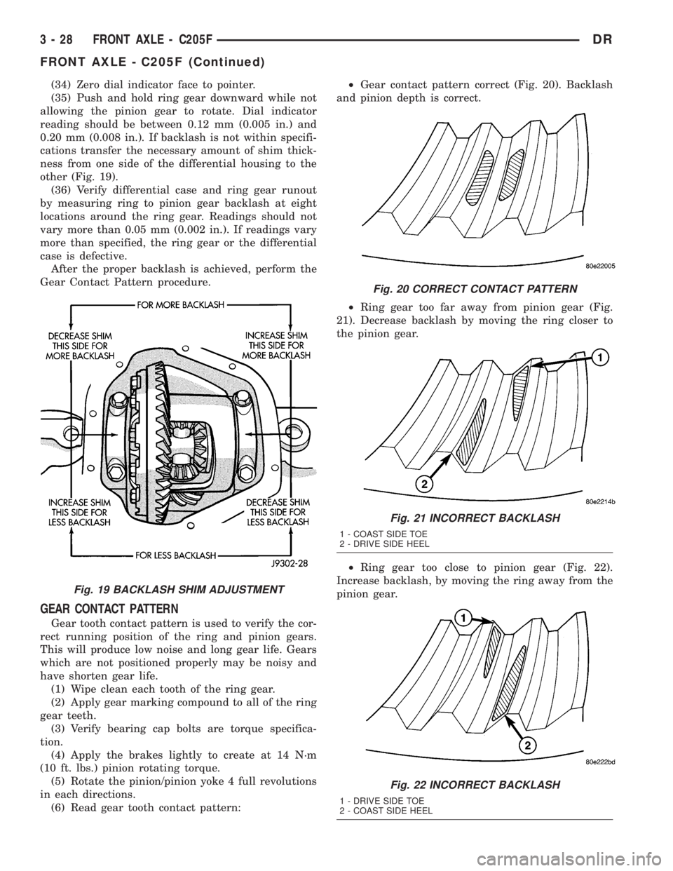
(34) Zero dial indicator face to pointer.
(35) Push and hold ring gear downward while not
allowing the pinion gear to rotate. Dial indicator
reading should be between 0.12 mm (0.005 in.) and
0.20 mm (0.008 in.). If backlash is not within specifi-
cations transfer the necessary amount of shim thick-
ness from one side of the differential housing to the
other (Fig. 19).
(36) Verify differential case and ring gear runout
by measuring ring to pinion gear backlash at eight
locations around the ring gear. Readings should not
vary more than 0.05 mm (0.002 in.). If readings vary
more than specified, the ring gear or the differential
case is defective.
After the proper backlash is achieved, perform the
Gear Contact Pattern procedure.
GEAR CONTACT PATTERN
Gear tooth contact pattern is used to verify the cor-
rect running position of the ring and pinion gears.
This will produce low noise and long gear life. Gears
which are not positioned properly may be noisy and
have shorten gear life.
(1) Wipe clean each tooth of the ring gear.
(2) Apply gear marking compound to all of the ring
gear teeth.
(3) Verify bearing cap bolts are torque specifica-
tion.
(4) Apply the brakes lightly to create at 14 N´m
(10 ft. lbs.) pinion rotating torque.
(5) Rotate the pinion/pinion yoke 4 full revolutions
in each directions.
(6) Read gear tooth contact pattern:²Gear contact pattern correct (Fig. 20). Backlash
and pinion depth is correct.
²Ring gear too far away from pinion gear (Fig.
21). Decrease backlash by moving the ring closer to
the pinion gear.
²Ring gear too close to pinion gear (Fig. 22).
Increase backlash, by moving the ring away from the
pinion gear.
Fig. 19 BACKLASH SHIM ADJUSTMENT
Fig. 20 CORRECT CONTACT PATTERN
Fig. 21 INCORRECT BACKLASH
1 - COAST SIDE TOE
2 - DRIVE SIDE HEEL
Fig. 22 INCORRECT BACKLASH
1 - DRIVE SIDE TOE
2 - COAST SIDE HEEL
3 - 28 FRONT AXLE - C205FDR
FRONT AXLE - C205F (Continued)
Page 108 of 2895
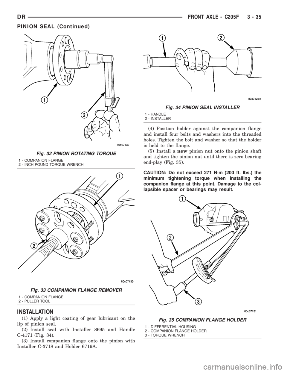
INSTALLATION
(1) Apply a light coating of gear lubricant on the
lip of pinion seal.
(2) Install seal with Installer 8695 and Handle
C-4171 (Fig. 34).
(3) Install companion flange onto the pinion with
Installer C-3718 and Holder 6719A.(4) Position holder against the companion flange
and install four bolts and washers into the threaded
holes. Tighten the bolt and washer so that the holder
is held to the flange.
(5) Install anewpinion nut onto the pinion shaft
and tighten the pinion nut until there is zero bearing
end-play (Fig. 35).
CAUTION: Do not exceed 271 N´m (200 ft. lbs.) the
minimum tightening torque when installing the
companion flange at this point. Damage to the col-
lapsible spacer or bearings may result.
Fig. 32 PINION ROTATING TORQUE
1 - COMPANION FLANGE
2 - INCH POUND TORQUE WRENCH
Fig. 33 COMPANION FLANGE REMOVER
1 - COMPANION FLANGE
2 - PULLER TOOL
Fig. 34 PINION SEAL INSTALLER
1 - HANDLE
2 - INSTALLER
Fig. 35 COMPANION FLANGE HOLDER
1 - DIFFERENTIAL HOUSING
2 - COMPANION FLANGE HOLDER
3 - TORQUE WRENCH
DRFRONT AXLE - C205F 3 - 35
PINION SEAL (Continued)