nv5600 DODGE RAM 2003 Service Repair Manual
[x] Cancel search | Manufacturer: DODGE, Model Year: 2003, Model line: RAM, Model: DODGE RAM 2003Pages: 2895, PDF Size: 83.15 MB
Page 5 of 2895
BODY CODE PLATE
DESCRIPTION
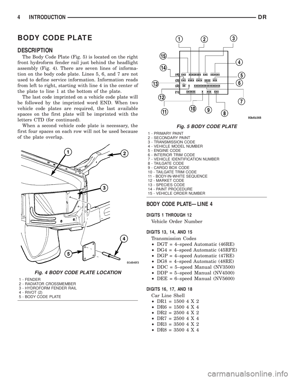
The Body Code Plate (Fig. 5) is located on the right
front hydroform fender rail just behind the headlight
assembly (Fig. 4). There are seven lines of informa-
tion on the body code plate. Lines 5, 6, and 7 are not
used to define service information. Information reads
from left to right, starting with line 4 in the center of
the plate to line 1 at the bottom of the plate.
The last code imprinted on a vehicle code plate will
be followed by the imprinted word END. When two
vehicle code plates are required, the last available
spaces on the first plate will be imprinted with the
letters CTD (for continued).
When a second vehicle code plate is necessary, the
first four spaces on each row will not be used because
of the plate overlap.
BODY CODE PLATEÐLINE 4
DIGITS 1 THROUGH 12
Vehicle Order Number
DIGITS 13, 14, AND 15
Transmission Codes
²DGT = 4±speed Automatic (46RE)
²DG4 = 4±speed Automatic (45RFE)
²DGP = 4±speed Automatic (47RE)
²DG8 = 4±speed Automatic (48RE)
²DDC = 5±speed Manual (NV3500)
²DDP = 5±speed Manual (NV4500)
²DEE = 6±speed Manual (NV5600)
DIGITS 16, 17, AND 18
Car Line Shell
²DR1=15004X2
²DR6=15004X4
²DR2=25004X2
²DR7=25004X4
²DR3=35004X2
²DR8=35004X4
Fig. 4 BODY CODE PLATE LOCATION
1 - FENDER
2 - RADIATOR CROSSMEMBER
3 - HYDROFORM FENDER RAIL
4 - RIVOT (2)
5 - BODY CODE PLATE
Fig. 5 BODY CODE PLATE
1 - PRIMARY PAINT
2 - SECONDARY PAINT
3 - TRANSMISSION CODE
4 - VEHICLE MODEL NUMBER
5 - ENGINE CODE
6 - INTERIOR TRIM CODE
7 - VEHICLE IDENTIFICATION NUMBER
8 - TAILGATE CODE
9 - CARGO BOX CODE
10 - TAILGATE TRIM CODE
11 - BODY-IN-WHITE SEQUENCE
12 - MARKET CODE
13 - SPECIES CODE
14 - PAINT PROCEDURE
15 - VEHICLE ORDER NUMBER
4 INTRODUCTIONDR
Page 17 of 2895
must alwaysbe a minimum of 44 percent, year-
round in all climates. If percentage is lower, engine
parts may be eroded by cavitation. Maximum protec-
tion against freezing is provided with a 68 percent
antifreeze concentration, which prevents freezing
down to -67.7ÉC (-90ÉF). A higher percentage will
freeze at a warmer temperature. Also, a higher per-
centage of antifreeze can cause the engine to over-
heat because specific heat of antifreeze is lower than
that of water.
CAUTION: Richer antifreeze mixtures cannot be
measured with normal field equipment and can
cause problems associated with 100 percent ethyl-
ene-glycol.
COOLANT SELECTION AND ADDITIVES
NOTE: Refer to the vehicle's coolant bottle to iden-
tify HOAT or Non-HOAT coolant. Non-HOAT coolant
is green in color.
The use of aluminum cylinder blocks, cylinder
heads and water pumps requires special corrosion
protection. Only MopartAntifreeze/Coolant, 5
Year/100,000 Mile Formula (glycol base coolant with
corrosion inhibitors called HOAT, for Hybrid Organic
Additive Technology) is recommended. This coolant
offers the best engine cooling without corrosion when
mixed with 50% distilled water to obtain to obtain a
freeze point of -37ÉC (-35ÉF). If it loses color or
becomes contaminated, drain, flush, and replace with
fresh properly mixed coolant solution.
CAUTION: Do not use coolant additives that are
claimed to improve engine cooling.
DESCRIPTION - TRANSFER CASE - NV241
GENII
Recommended lubricant for the NV241 GENII
transfer case is MopartATF +4, Automatic Trans-
mission Fluid.
DESCRIPTION - TRANSFER CASE - NV271
Recommended lubricant for the NV271 transfer
case is MopartATF +4, Automatic Transmission
Fluid.
DESCRIPTION - TRANSFER CASE - NV243
Recommended lubricant for the NV243 transfer case
is MopartATF +4, Automatic Transmission Fluid.
DESCRIPTION - TRANSFER CASE - NV273
Recommended lubricant for the NV273 transfer case
is MopartATF +4, Automatic Transmission Fluid.
DESCRIPTION - AXLE
NOTE: DaimlerChrysler recommends using MoparT
lubricants or lubricants of equal quality.
FRONT AXLE
²C205F - MopartGear Lubricant 75W-90
²9 1/4 AA - MopartSynthetic Gear Lubricant
75W-90
REAR AXLE
²9 1/4 - MopartSynthetic Gear Lubricant 75W-140
²10 1/2 AA - MopartSynthetic Gear Lubricant
75W-90
²11 1/2 AA - MopartSynthetic Gear Lubricant
75W-90
NOTE: Trac-LokTdifferentials require Limited Slip
Additive in the lubricant. Trac-RiteŸ differentials
DO NOT require Limited Slip Additive.
DESCRIPTION - MANUAL TRANSMISSION
NOTE: DaimlerChrysler recommends using MoparT
lubricants or lubricants of equal quality.
²
NV3500 - MopartManual Transmission Lubricant
²NV4500 - MopartSynthetic 75W85 Manual
Transmission Lubricant
²NV5600 - MopartManual Transmission Lubri-
cant
DESCRIPTION - AUTOMATIC TRANSMISSION
FLUID
NOTE: Refer to Service Procedures in this group for
fluid level checking procedures.
MopartATF +4, Automatic Transmission Fluid is
the recommended fluid for DaimlerChrysler auto-
matic transmissions.
Dexron II fluid IS NOT recommended. Clutch
chatter can result from the use of improper
fluid.
MopartATF +4, Automatic Transmission Fluid
when new is red in color. The ATF is dyed red so it
can be identified from other fluids used in the vehicle
such as engine oil or antifreeze. The red color is not
permanent and is not an indicator of fluid condition.
As the vehicle is driven, the ATF will begin to look
darker in color and may eventually become brown.
This is normal.ATF+4 also has a unique odor that
may change with age. Consequently, odor and color
cannot be used to indicate the fluid condition or the
need for a fluid change.
0 - 4 LUBRICATION & MAINTENANCEDR
FLUID TYPES (Continued)
Page 18 of 2895
FLUID ADDITIVES
DaimlerChrysler strongly recommends against the
addition of any fluids to the transmission, other than
those automatic transmission fluids listed above.
Exceptions to this policy are the use of special dyes
to aid in detecting fluid leaks.
Various ªspecialº additives and supplements exist
that claim to improve shift feel and/or quality. These
additives and others also claim to improve converter
clutch operation and inhibit overheating, oxidation,
varnish, and sludge. These claims have not been sup-
ported to the satisfaction of DaimlerChrysler and
these additivesmust not be used.The use of trans-
mission ªsealersº should also be avoided, since they
may adversely affect the integrity of transmission
seals.
OPERATION - AUTOMATIC TRANSMISSION
FLUID
The automatic transmission fluid is selected based
upon several qualities. The fluid must provide a high
level of protection for the internal components by
providing a lubricating film between adjacent metal
components. The fluid must also be thermally stable
so that it can maintain a consistent viscosity through
a large temperature range. If the viscosity stays con-
stant through the temperature range of operation,
transmission operation and shift feel will remain con-
sistent. Transmission fluid must also be a good con-
ductor of heat. The fluid must absorb heat from the
internal transmission components and transfer that
heat to the transmission case.
FLUID CAPACITIES
SPECIFICATIONS
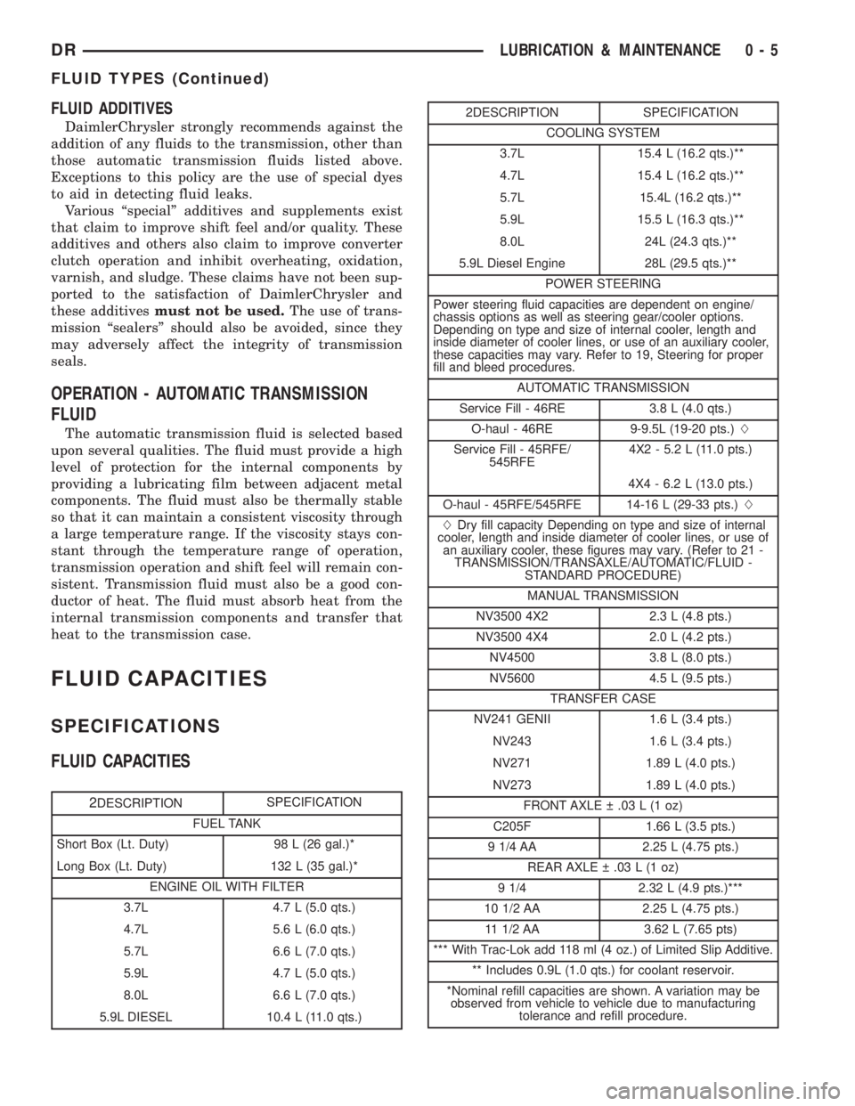
FLUID CAPACITIES
2DESCRIPTIONSPECIFICATION
FUEL TANK
Short Box (Lt. Duty) 98 L (26 gal.)*
Long Box (Lt. Duty) 132 L (35 gal.)*
ENGINE OIL WITH FILTER
3.7L 4.7 L (5.0 qts.)
4.7L 5.6 L (6.0 qts.)
5.7L 6.6 L (7.0 qts.)
5.9L 4.7 L (5.0 qts.)
8.0L 6.6 L (7.0 qts.)
5.9L DIESEL 10.4 L (11.0 qts.)
2DESCRIPTION SPECIFICATION
COOLING SYSTEM
3.7L 15.4 L (16.2 qts.)**
4.7L 15.4 L (16.2 qts.)**
5.7L 15.4L (16.2 qts.)**
5.9L 15.5 L (16.3 qts.)**
8.0L 24L (24.3 qts.)**
5.9L Diesel Engine 28L (29.5 qts.)**
POWER STEERING
Power steering fluid capacities are dependent on engine/
chassis options as well as steering gear/cooler options.
Depending on type and size of internal cooler, length and
inside diameter of cooler lines, or use of an auxiliary cooler,
these capacities may vary. Refer to 19, Steering for proper
fill and bleed procedures.
AUTOMATIC TRANSMISSION
Service Fill - 46RE 3.8 L (4.0 qts.)
O-haul - 46RE 9-9.5L (19-20 pts.)L
Service Fill - 45RFE/
545RFE4X2 - 5.2 L (11.0 pts.)
4X4 - 6.2 L (13.0 pts.)
O-haul - 45RFE/545RFE 14-16 L (29-33 pts.)L
LDry fill capacity Depending on type and size of internal
cooler, length and inside diameter of cooler lines, or use of
an auxiliary cooler, these figures may vary. (Refer to 21 -
TRANSMISSION/TRANSAXLE/AUTOMATIC/FLUID -
STANDARD PROCEDURE)
MANUAL TRANSMISSION
NV3500 4X2 2.3 L (4.8 pts.)
NV3500 4X4 2.0 L (4.2 pts.)
NV4500 3.8 L (8.0 pts.)
NV5600 4.5 L (9.5 pts.)
TRANSFER CASE
NV241 GENII 1.6 L (3.4 pts.)
NV243 1.6 L (3.4 pts.)
NV271 1.89 L (4.0 pts.)
NV273 1.89 L (4.0 pts.)
FRONT AXLE .03 L (1 oz)
C205F 1.66 L (3.5 pts.)
9 1/4 AA 2.25 L (4.75 pts.)
REAR AXLE .03 L (1 oz)
9 1/4 2.32 L (4.9 pts.)***
10 1/2 AA 2.25 L (4.75 pts.)
11 1/2 AA 3.62 L (7.65 pts)
*** With Trac-Lok add 118 ml (4 oz.) of Limited Slip Additive.
** Includes 0.9L (1.0 qts.) for coolant reservoir.
*Nominal refill capacities are shown. A variation may be
observed from vehicle to vehicle due to manufacturing
tolerance and refill procedure.
DRLUBRICATION & MAINTENANCE 0 - 5
FLUID TYPES (Continued)
Page 281 of 2895
(14) Check fluid level in clutch master cylinder.
CLUTCH HOUSING
DIAGNOSIS AND TESTING
The clutch housing maintains alignment between
the crankshaft and transmission input shaft. Mis-
alignment can cause clutch noise, hard shifting,
incomplete release and chatter. Also premature pilot
bearing, cover release fingers and clutch disc wear.
In severe cases, it can cause premature wear of the
transmission input shaft and front bearing.
NOTE: Only the NV4500 clutch housing can be
checked using the following bore and face runout
procedures. The NV5600 clutch housing is a inte-
gral part of the transmission and can only be
checked off the vehicle.
CLUTCH HOUSING BORE RUNOUT
CAUTION: On diesel engines if housing bore runout
exceeds 0.015 inch, the clutch housing/transmis-
sion adapter plate must be replaced. On gas
engines if housing bore runout exceeds 0.053 in.
the clutch housing must be replaced.
NOTE: Offset dowels are available for gas engines
to correct housing bore runout. They are not avail-
able for diesel engines.
(1) Remove the clutch housing.
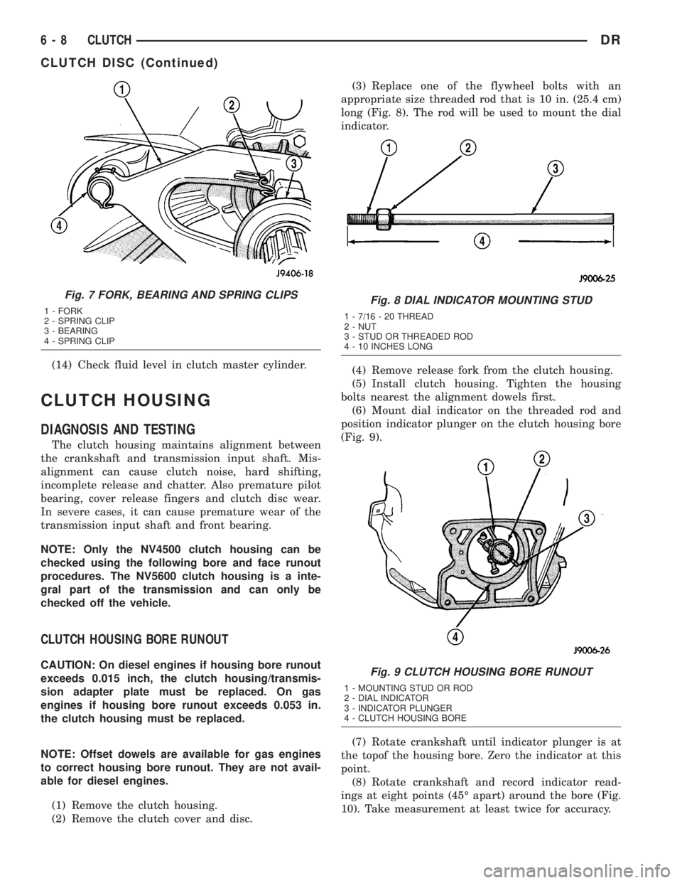
(2) Remove the clutch cover and disc.(3) Replace one of the flywheel bolts with an
appropriate size threaded rod that is 10 in. (25.4 cm)
long (Fig. 8). The rod will be used to mount the dial
indicator.
(4) Remove release fork from the clutch housing.
(5) Install clutch housing. Tighten the housing
bolts nearest the alignment dowels first.
(6) Mount dial indicator on the threaded rod and
position indicator plunger on the clutch housing bore
(Fig. 9).
(7) Rotate crankshaft until indicator plunger is at
the topof the housing bore. Zero the indicator at this
point.
(8) Rotate crankshaft and record indicator read-
ings at eight points (45É apart) around the bore (Fig.
10). Take measurement at least twice for accuracy.
Fig. 7 FORK, BEARING AND SPRING CLIPS
1 - FORK
2 - SPRING CLIP
3 - BEARING
4 - SPRING CLIPFig. 8 DIAL INDICATOR MOUNTING STUD
1 - 7/16 - 20 THREAD
2 - NUT
3 - STUD OR THREADED ROD
4 - 10 INCHES LONG
Fig. 9 CLUTCH HOUSING BORE RUNOUT
1 - MOUNTING STUD OR ROD
2 - DIAL INDICATOR
3 - INDICATOR PLUNGER
4 - CLUTCH HOUSING BORE
6 - 8 CLUTCHDR
CLUTCH DISC (Continued)
Page 1840 of 2895
TRANSMISSION AND TRANSFER CASE
TABLE OF CONTENTS
page page
MANUAL TRANSMISSION - NV3500..........1
MANUAL TRANSMISSION - NV4500..........42
MANUAL TRANSMISSION - NV5600..........87
AUTOMATIC TRANSMISSION - 46RE........129
AUTOMATIC TRANSMISSION - 48RE........310
AUTOMATIC TRANSMISSION - 45RFE/545RFE. . 488
TRANSFER CASE - NV241 GENII...........591
TRANSFER CASE - NV271................623
TRANSFER CASE - NV243................658
TRANSFER CASE - NV273................687
MANUAL TRANSMISSION - NV3500
TABLE OF CONTENTS
page page
MANUAL TRANSMISSION - NV3500
DESCRIPTION..........................1
OPERATION............................1
DIAGNOSIS AND TESTING................3
REMOVAL.............................3
DISASSEMBLY..........................4CLEANING............................15
INSPECTION..........................15
ASSEMBLY............................17
INSTALLATION.........................38
SPECIFICATIONS.......................39
SPECIAL TOOLS.......................40
MANUAL TRANSMISSION -
NV3500
DESCRIPTION
The transmission is a medium-duty 5-speed, con-
stant mesh fully synchronized manual transmission
with fifth gear overdrive range. The transmission is
available in two and four-wheel drive configurations.
The transmission gear case consists of two aluminum
housings (Fig. 1). The clutch housing is an integral
part of the transmission front housing.
A combination of roller and ball bearings are used
to support the transmission shafts in the two hous-
ings. The transmission gears all rotate on caged type
needle bearings. A roller bearing is used between the
input and output shaft.
The transmission has a single shaft shift mecha-
nism with three shift forks all mounted on the shaft.
The shaft is supported in the front and rear housings
by bushings and one linear ball bearing. Internal
shift components consist of the forks, shaft, shift
lever socket and detent components
OPERATION
The manual transmission receives power through the
clutch assembly from the engine. The clutch disc issplined to the transmission input shaft and is turned at
engine speed at all times that the clutch is engaged.
The input shaft is connected to the transmission coun-
tershaft through the mesh of fourth speed gear on the
input shaft and the fourth countershaft gear. At this
point, all the transmission gears are spinning.
The driver selects a particular gear by moving the
shift lever to the desired gear position. This move-
ment moves the internal transmission shift compo-
nents to begin the shift sequence. As the shift lever
moves the selected shift rail, the shift fork attached
to that rail begins to move. The fork is positioned in
a groove in the outer circumference of the synchro-
nizer sleeve. As the shift fork moves the synchronizer
sleeve, the synchronizer begins to speed-up or slow
down the selected gear (depending on whether we are
up-shifting or down-shifting). The synchronizer does
this by having the synchronizer hub splined to the
mainshaft and moving the blocker ring into contact
with the gear's friction cone. As the blocker ring and
friction cone come together, the gear speed is brought
up or down to the speed of the synchronizer. As the
two speeds match, the splines on the inside of the
synchronizer sleeve become aligned with the teeth on
the blocker ring and the friction cone and eventually
will slide over the teeth, locking the gear to the
mainshaft, or countershaft, through the synchronizer.
DRTRANSMISSION AND TRANSFER CASE 21 - 1
Page 1926 of 2895
MANUAL TRANSMISSION - NV5600
TABLE OF CONTENTS
page page
MANUAL TRANSMISSION - NV5600
DESCRIPTION.........................87
OPERATION...........................89
DIAGNOSIS AND TESTING................89
REMOVAL.............................89
DISASSEMBLY.........................90
CLEANING - TRANSMISSION.............104
INSPECTION.........................104
ASSEMBLY...........................105
INSTALLATION........................120
SPECIFICATIONS - NV5600..............122SPECIAL TOOLS.......................122
ADAPTER HOUSING SEAL
REMOVAL............................127
INSTALLATION........................127
EXTENSION HOUSING SEAL
REMOVAL............................127
INSTALLATION........................127
SHIFT COVER
REMOVAL............................128
INSTALLATION........................128
MANUAL TRANSMISSION -
NV5600
DESCRIPTION
The NV5600 is a six speed constant mesh manual
transmission (Fig. 1). All gear ranges including
reverse are synchronized. First and second gears uti-
lize dual cone synchronizers in order to aid shifting.
Sixth gear is an overdrive range. The transmission
uses cast iron for the gear case and extension/
adapter housing and aluminum for the clutch hous-
ing.To drain the trans remove the bottom PTO cover
bolt. Fill the trans through the plug to the rear of the
PTO cover (Fig. 1). Dry fill is approximately 4.5 liters
(9.5 pints) or to the bottom edge of the fill plug hole.
The gear ratios are:GEAR RATIOS
GEAR RATIO
FIRST 5.63:1
SECOND 3.38:1
THIRD 2.04:1
FOURTH 1.39:1
FIFTH 1.00:1
SIXTH 0.73:1
REVERSE 5.63:1
DRMANUAL TRANSMISSION - NV5600 21 - 87
Page 1927 of 2895

Fig. 1 NV5600 MANUAL TRANSMISSION
21 - 88 MANUAL TRANSMISSION - NV5600DR
MANUAL TRANSMISSION - NV5600 (Continued)
Page 1928 of 2895
IDENTIFICATION
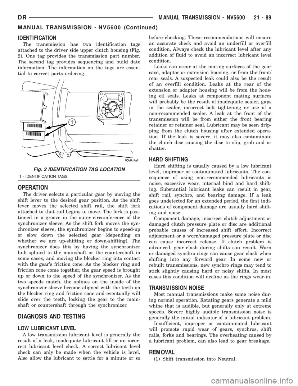
The transmission has two identification tags
attached to the driver side upper clutch housing (Fig.
2). One tag provides the transmission part number.
The second tag provides sequencing and build date
information. The information on the tags are essen-
tial to correct parts ordering.
OPERATION
The driver selects a particular gear by moving the
shift lever to the desired gear position. As the shift
lever moves the selected shift rail, the shift fork
attached to that rail begins to move. The fork is posi-
tioned in a groove in the outer circumference of the
synchronizer sleeve. As the shift fork moves the syn-
chronizer sleeve, the synchronizer begins to speed-up
or slow down the selected gear (depending on
whether we are up-shifting or down-shifting). The
synchronizer does this by having the synchronizer
hub splined to the mainshaft or the countershaft in
some cases, and moving the blocker ring into contact
with the gear's friction cone. As the blocker ring and
friction cone come together, the gear speed is brought
up or down to the speed of the synchronizer. As the
two speeds match, the splines on the inside of the
synchronizer sleeve become aligned with the teeth on
the blocker ring and friction cone and eventually will
slide over the teeth, locking the gear to the main-
shaft or countershaft through the synchronizer.
DIAGNOSIS AND TESTING
LOW LUBRICANT LEVEL
A low transmission lubricant level is generally the
result of a leak, inadequate lubricant fill or an incor-
rect lubricant level check. A correct lubricant level
check can only be made when the vehicle is level.
Also allow the lubricant to settle for a minute or sobefore checking. These recommendations will ensure
an accurate check and avoid an underfill or overfill
condition. Always check the lubricant level after any
addition of fluid to avoid an incorrect lubricant level
condition.
Leaks can occur at the mating surfaces of the gear
case, adaptor or extension housing, or from the front/
rear seals. A suspected leak could also be the result
of an overfill condition. Leaks at the rear of the
extension or adapter housing will be from the hous-
ing oil seals. Leaks at component mating surfaces
will probably be the result of inadequate sealer, gaps
in the sealer, incorrect bolt tightening or use of a
non-recommended sealer. A leak at the front of the
transmission will be from either the front bearing
retainer or retainer seal. Lubricant may be seen drip-
ping from the clutch housing after extended opera-
tion. If the leak is severe, it may also contaminate
the clutch disc causing the disc to slip, grab and or
chatter.
HARD SHIFTING
Hard shifting is usually caused by a low lubricant
level, improper or contaminated lubricants. The con-
sequence of using non-recommended lubricants is
noise, excessive wear, internal bind and hard shift-
ing. Substantial lubricant leaks can result in gear,
shift rail, synchro, and bearing damage. If a leak
goes undetected for an extended period, the first indi-
cations of component damage are usually hard shift-
ing and noise.
Component damage, incorrect clutch adjustment or
damaged clutch pressure plate or disc are additional
probable causes of increased shift effort. Incorrect
adjustment or a worn/damaged pressure plate or disc
can cause incorrect release. If clutch problem is
advanced, gear clash during shifts can result. Worn
or damaged synchro rings can cause gear clash when
shifting into any forward gear. In some new or
rebuilt transmissions, new synchro rings may tend to
stick slightly causing hard or noisy shifts. In most
cases this condition will decline as the rings wear-in.
TRANSMISSION NOISE
Most manual transmissions make some noise dur-
ing normal operation. Rotating gears generate a mild
whine that is audible, but generally only at extreme
speeds. Severe highly audible transmission noise is
generally the initial indicator of a lubricant problem.
Insufficient, improper or contaminated lubricant
will promote rapid wear of gears, synchros, shift
rails, forks and bearings. The overheating caused by
a lubricant problem, can also lead to gear breakage.
REMOVAL
(1) Shift transmission into Neutral.
Fig. 2 IDENTIFICATION TAG LOCATION
1 - IDENTIFICATION TAGS
DRMANUAL TRANSMISSION - NV5600 21 - 89
MANUAL TRANSMISSION - NV5600 (Continued)
Page 1929 of 2895
(2) Remove screws attaching shift boot to floorpan.
Then slide boot upward on the shift lever.
(3) Remove the bolts holding the shift tower to the
isolator plate and transmission gear case.
(4) Remove the shift tower and isolator plate from
the transmission gear case.
(5) Raise and support vehicle.
(6) Remove skid plate, if equipped.
(7) Mark propeller shaft/shafts and axle yokes for
installation reference.
(8) Remove propeller shaft.
(9) Disconnect and remove exhaust system as nec-
essary.
(10) Disconnect wires at backup light switch.
(11) Support engine with adjustable safety stand
and wood block.
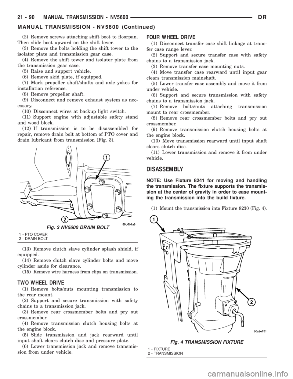
(12) If transmission is to be disassembled for
repair, remove drain bolt at bottom of PTO cover and
drain lubricant from transmission (Fig. 3).
(13) Remove clutch slave cylinder splash shield, if
equipped.
(14) Remove clutch slave cylinder bolts and move
cylinder aside for clearance.
(15)
Remove wire harness from clips on transmission.
TWO WHEEL DRIVE
(1) Remove bolts/nuts mounting transmission to
the rear mount.
(2) Support and secure transmission with safety
chains to a transmission jack.
(3) Remove rear crossmember bolts and pry out
crossmember.
(4) Remove transmission clutch housing bolts at
the engine block.
(5) Slide transmission and jack rearward until
input shaft clears clutch disc and pressure plate.
(6) Lower transmission jack and remove transmis-
sion from under vehicle.
FOUR WHEEL DRIVE
(1) Disconnect transfer case shift linkage at trans-
fer case range lever.
(2) Support and secure transfer case with safety
chains to a transmission jack.
(3) Remove transfer case mounting nuts.
(4) Move transfer case rearward until input gear
clears transmission mainshaft.
(5) Lower transfer case assembly and move it from
under vehicle.
(6) Support and secure transmission with safety
chains to a transmission jack.
(7) Remove bolts/nuts attaching transmission
mount to rear crossmember.
(8) Remove rear crossmember bolts and pry out
crossmember.
(9) Remove transmission clutch housing bolts at
the engine block.
(10) Move transmission rearward until input shaft
clears clutch disc.
(11) Lower transmission and remove it from under
vehicle.
DISASSEMBLY
NOTE: Use Fixture 8241 for moving and handling
the transmission. The fixture supports the transmis-
sion at the center of gravity in order to ease mount-
ing the transmission into the build fixture.
(1)
Mount the transmission into Fixture 8230 (Fig. 4).
Fig. 3 NV5600 DRAIN BOLT
1 - PTO COVER
2 - DRAIN BOLT
Fig. 4 TRANSMISSION FIXTURE
1 - FIXTURE
2 - TRANSMISSION
21 - 90 MANUAL TRANSMISSION - NV5600DR
MANUAL TRANSMISSION - NV5600 (Continued)
Page 1930 of 2895
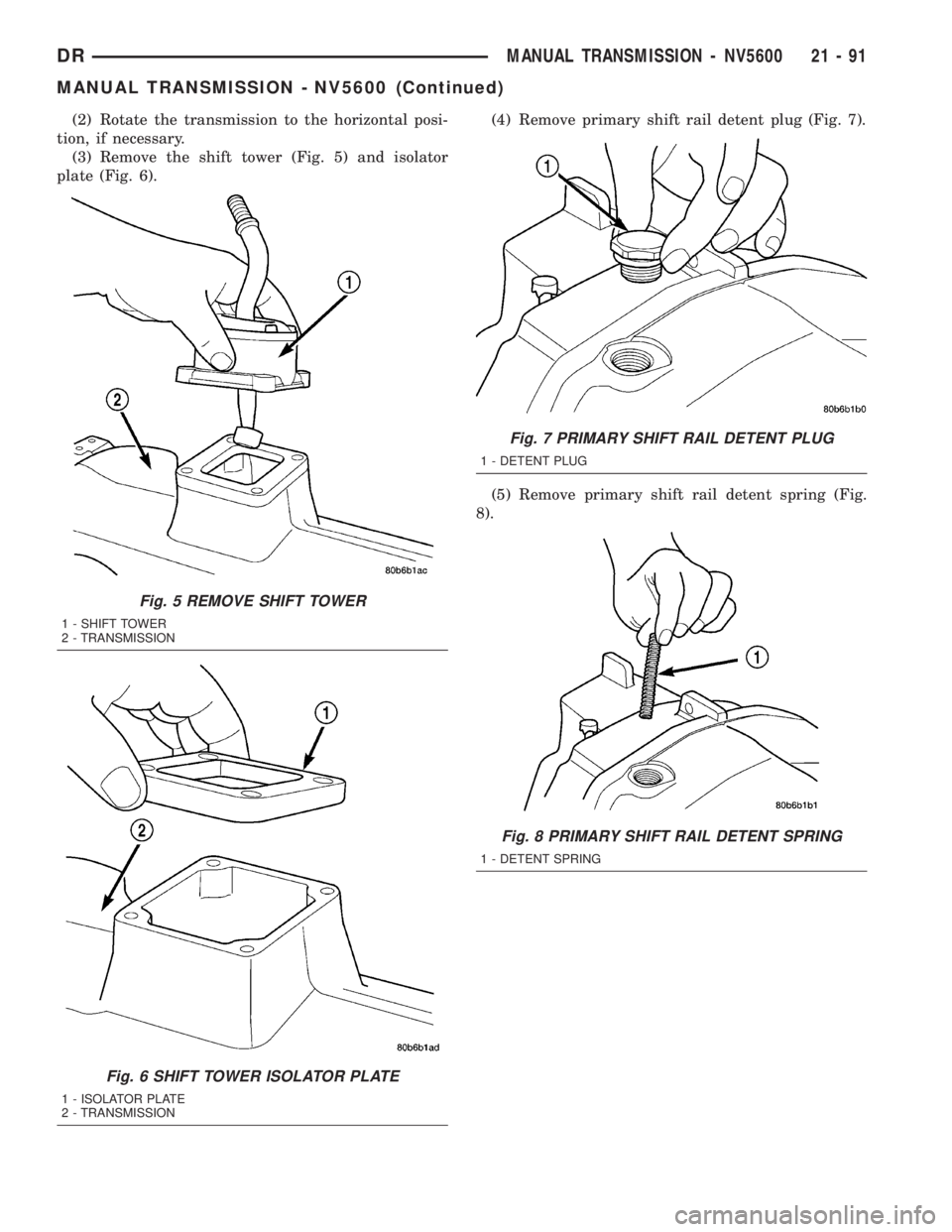
(2) Rotate the transmission to the horizontal posi-
tion, if necessary.
(3) Remove the shift tower (Fig. 5) and isolator
plate (Fig. 6).(4) Remove primary shift rail detent plug (Fig. 7).
(5) Remove primary shift rail detent spring (Fig.
8).
Fig. 5 REMOVE SHIFT TOWER
1 - SHIFT TOWER
2 - TRANSMISSION
Fig. 6 SHIFT TOWER ISOLATOR PLATE
1 - ISOLATOR PLATE
2 - TRANSMISSION
Fig. 7 PRIMARY SHIFT RAIL DETENT PLUG
1 - DETENT PLUG
Fig. 8 PRIMARY SHIFT RAIL DETENT SPRING
1 - DETENT SPRING
DRMANUAL TRANSMISSION - NV5600 21 - 91
MANUAL TRANSMISSION - NV5600 (Continued)