reset DODGE RAM 2003 Service Repair Manual
[x] Cancel search | Manufacturer: DODGE, Model Year: 2003, Model line: RAM, Model: DODGE RAM 2003Pages: 2895, PDF Size: 83.15 MB
Page 34 of 2895
angle while adjusting caster, move one pivot bolt of
the upper control arm in or out. Then move the other
pivot bolt of the upper control arm in the opposite
direction. Install special tool 8876 between the top of
the upper control arm bracket and the upper control
arm (on 1500 series 4X2 & 4X4). Install special tool
8876 between the bottom of the upper control arm
bracket pressing the tool against the frame and the
upper control arm (on 2500/3500 series 4X2) in order
to move the upper control arm outwards for proper
adjustment with the vehicle at normal ride height
(Fig. 3).
To increase positive caster angle, move the rear
position of the upper control arm inward (toward the
engine). Move the front of the upper control arm out-
ward (away from the engine) slightly until the origi-
nal camber angle is obtained using special tool 8876
to move the upper control arm for proper adjustment.
(Fig. 3)
CAMBER
Move both pivot bolts of the upper control arm
together in or out. This will change the camber angle
significantly and little effect on the caster angle
using special tool 8876 to move the upper control
arm for proper adjustment. (Fig. 3)
After adjustment is made tighten the upper control
arm nuts to proper torque specification.
TOE ADJUSTMENT
The wheel toe position adjustment is the final
adjustment.
(1) Start the engine and turn wheels both ways
before straightening the wheels. Secure the steering
wheel with the front wheels in the straight-ahead
position.
(2) Loosen the tie rod jam nuts.
NOTE: Each front wheel should be adjusted for
one-half of the total toe position specification. This
will ensure the steering wheel will be centered
when the wheels are positioned straight-ahead.
(3) Adjust the wheel toe position by turning the
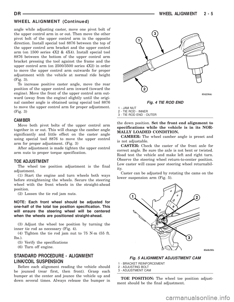
inner tie rod as necessary (Fig. 4).
(4) Tighten the tie rod jam nut to 75 N´m (55 ft.
lbs.).
(5) Verify the specifications
(6) Turn off engine.
STANDARD PROCEDURE - ALIGNMENT
LINK/COIL SUSPENSION
Before each alignment reading the vehicle should
be jounced (rear first, then front). Grasp each
bumper at the center and jounce the vehicle up and
down several times. Always release the bumper inthe down position.Set the front end alignment to
specifications while the vehicle is in its NOR-
MALLY LOADED CONDITION.
CAMBER:The wheel camber angle is preset and
is not adjustable.
CASTER:Check the caster of the front axle for
correct angle. Be sure the axle is not bent or twisted.
Road test the vehicle and make left and right turn.
Observe the steering wheel return-to-center position.
Low caster will cause poor steering wheel returnabil-
ity.
Caster can be adjusted by rotating the cams on the
lower suspension arm (Fig. 5).
TOE POSITION:The wheel toe position adjust-
ment should be the final adjustment.
Fig. 4 TIE ROD END
1 - JAM NUT
2 - TIE ROD - INNER
3 - TIE ROD END - OUTER
Fig. 5 ALIGNMENT ADJUSTMENT CAM
1 - BRACKET REINFORCEMENT
2 - ADJUSTING BOLT
3 - ADJUSTMENT CAM
DRWHEEL ALIGNMENT 2 - 5
WHEEL ALIGNMENT (Continued)
Page 43 of 2895
FRAME MOUNTED BUSHING
NOTE: Extreme pressure lubrication must be used
on the threaded portions of the tool. This will
increase the longevity of the tool and insure proper
operation during the removal and installation pro-
cess.
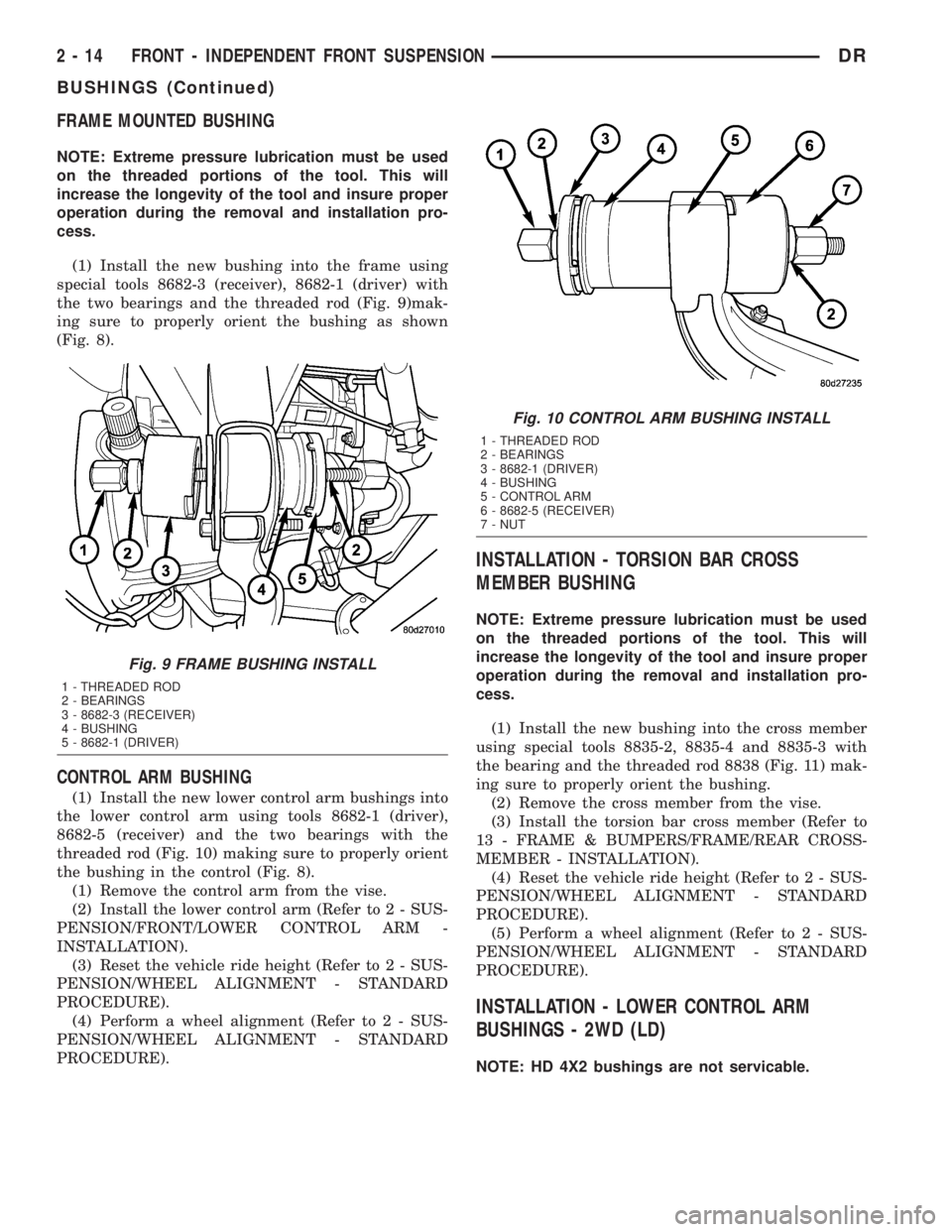
(1) Install the new bushing into the frame using
special tools 8682-3 (receiver), 8682-1 (driver) with
the two bearings and the threaded rod (Fig. 9)mak-
ing sure to properly orient the bushing as shown
(Fig. 8).
CONTROL ARM BUSHING
(1) Install the new lower control arm bushings into
the lower control arm using tools 8682-1 (driver),
8682-5 (receiver) and the two bearings with the
threaded rod (Fig. 10) making sure to properly orient
the bushing in the control (Fig. 8).
(1) Remove the control arm from the vise.
(2) Install the lower control arm (Refer to 2 - SUS-
PENSION/FRONT/LOWER CONTROL ARM -
INSTALLATION).
(3) Reset the vehicle ride height (Refer to 2 - SUS-
PENSION/WHEEL ALIGNMENT - STANDARD
PROCEDURE).
(4) Perform a wheel alignment (Refer to 2 - SUS-
PENSION/WHEEL ALIGNMENT - STANDARD
PROCEDURE).
INSTALLATION - TORSION BAR CROSS
MEMBER BUSHING
NOTE: Extreme pressure lubrication must be used
on the threaded portions of the tool. This will
increase the longevity of the tool and insure proper
operation during the removal and installation pro-
cess.
(1) Install the new bushing into the cross member
using special tools 8835-2, 8835-4 and 8835-3 with
the bearing and the threaded rod 8838 (Fig. 11) mak-
ing sure to properly orient the bushing.
(2) Remove the cross member from the vise.
(3) Install the torsion bar cross member (Refer to
13 - FRAME & BUMPERS/FRAME/REAR CROSS-
MEMBER - INSTALLATION).
(4) Reset the vehicle ride height (Refer to 2 - SUS-
PENSION/WHEEL ALIGNMENT - STANDARD
PROCEDURE).
(5) Perform a wheel alignment (Refer to 2 - SUS-
PENSION/WHEEL ALIGNMENT - STANDARD
PROCEDURE).
INSTALLATION - LOWER CONTROL ARM
BUSHINGS - 2WD (LD)
NOTE: HD 4X2 bushings are not servicable.
Fig. 9 FRAME BUSHING INSTALL
1 - THREADED ROD
2 - BEARINGS
3 - 8682-3 (RECEIVER)
4 - BUSHING
5 - 8682-1 (DRIVER)
Fig. 10 CONTROL ARM BUSHING INSTALL
1 - THREADED ROD
2 - BEARINGS
3 - 8682-1 (DRIVER)
4 - BUSHING
5 - CONTROL ARM
6 - 8682-5 (RECEIVER)
7 - NUT
2 - 14 FRONT - INDEPENDENT FRONT SUSPENSIONDR
BUSHINGS (Continued)
Page 44 of 2895
LARGE BUSHING
NOTE: Extreme pressure lubrication must be used
on the threaded portions of the tool. This will
increase the longevity of the tool and insure proper
operation during the removal and installation pro-
cess.
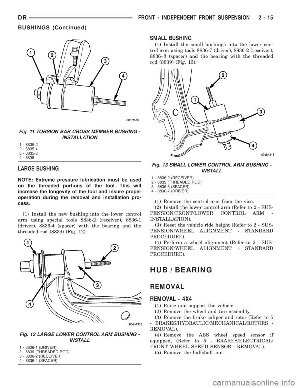
(1) Install the new bushing into the lower control
arm using special tools 8836-2 (receiver), 8836-1
(driver), 8836-4 (spacer) with the bearing and the
threaded rod (8839) (Fig. 12).
SMALL BUSHING
(1) Install the small bushings into the lower con-
trol arm using tools 8836-7 (driver), 8836-2 (receiver),
8836±3 (spacer) and the bearing with the threaded
rod (8839) (Fig. 13).
(1) Remove the control arm from the vise.
(2) Install the lower control arm (Refer to 2 - SUS-
PENSION/FRONT/LOWER CONTROL ARM -
INSTALLATION).
(3) Reset the vehicle ride height (Refer to 2 - SUS-
PENSION/WHEEL ALIGNMENT - STANDARD
PROCEDURE).
(4) Perform a wheel alignment (Refer to 2 - SUS-
PENSION/WHEEL ALIGNMENT - STANDARD
PROCEDURE).
HUB / BEARING
REMOVAL
REMOVAL - 4X4
(1) Raise and support the vehicle.
(2) Remove the wheel and tire assembly.
(3) Remove the brake caliper and rotor (Refer to 5
- BRAKES/HYDRAULIC/MECHANICAL/ROTORS -
REMOVAL).
(4) Remove the ABS wheel speed sensor if
equipped, (Refer to 5 - BRAKES/ELECTRICAL/
FRONT WHEEL SPEED SENSOR - REMOVAL).
(5) Remove the halfshaft nut.
Fig. 11 TORSION BAR CROSS MEMBER BUSHING -
INSTALLATION
1 - 8835-2
2 - 8835-4
3 - 8835-3
4 - 8838
Fig. 12 LARGE LOWER CONTROL ARM BUSHING -
INSTALL
1 - 8836-1 (DRIVER)
2 - 8839 (THREADED ROD)
3 - 8836-2 (RECEIVER)
4 - 8836-4 (SPACER)
Fig. 13 SMALL LOWER CONTROL ARM BUSHING -
INSTALL
1 - 8836-2 (RECEIVER)
2 - 8839 (THREADED ROD)
3 - 8836-3 (SPACER)
4 - 8836-7 (DRIVER)
DRFRONT - INDEPENDENT FRONT SUSPENSION 2 - 15
BUSHINGS (Continued)
Page 262 of 2895
NOTE: When measuring the brake drum diameter,
the diameter should be measured in the center of
the area in which the park brake shoes contact the
surface of the brake drum.
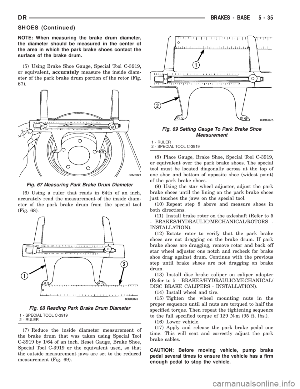
(5) Using Brake Shoe Gauge, Special Tool C-3919,
or equivalent,accuratelymeasure the inside diam-
eter of the park brake drum portion of the rotor (Fig.
67).
(6) Using a ruler that reads in 64th of an inch,
accurately read the measurement of the inside diam-
eter of the park brake drum from the special tool
(Fig. 68).
(7) Reduce the inside diameter measurement of
the brake drum that was taken using Special Tool
C-3919 by 1/64 of an inch. Reset Gauge, Brake Shoe,
Special Tool C-3919 or the equivalent used, so that
the outside measurement jaws are set to the reduced
measurement (Fig. 69).(8) Place Gauge, Brake Shoe, Special Tool C-3919,
or equivalent over the park brake shoes. The special
tool must be located diagonally across at the top of
one shoe and bottom of opposite shoe (widest point)
of the park brake shoes.
(9) Using the star wheel adjuster, adjust the park
brake shoes until the lining on the park brake shoes
just touches the jaws on the special tool.
(10) Repeat step 8 above and measure shoes in
both directions.
(11) Install brake rotor on the axleshaft (Refer to 5
- BRAKES/HYDRAULIC/MECHANICAL/ROTORS -
INSTALLATION).
(12) Rotate rotor to verify that the park brake
shoes are not dragging on the brake drum. If park
brake shoes are dragging, remove rotor and back off
star wheel adjuster one notch and recheck for brake
shoe drag against drum. Continue with the previous
step until brake shoes are not dragging on brake
drum.
(13) Install disc brake caliper on caliper adapter
(Refer to 5 - BRAKES/HYDRAULIC/MECHANICAL/
DISC BRAKE CALIPERS - INSTALLATION).
(14) Install wheel and tire.
(15) Tighten the wheel mounting nuts in the
proper sequence until all nuts are torqued to half the
specified torque. Then repeat the tightening sequence
to the full specified torque of 129 N´m (95 ft. lbs.).
(16) Lower vehicle.
(17) Apply and release the park brake pedal one
time. This will seat and correctly adjust the park
brake cables.
CAUTION: Before moving vehicle, pump brake
pedal several times to ensure the vehicle has a firm
enough pedal to stop the vehicle.
Fig. 67 Measuring Park Brake Drum Diameter
Fig. 68 Reading Park Brake Drum Diameter
1 - SPECIAL TOOL C-3919
2 - RULER
Fig. 69 Setting Gauge To Park Brake Shoe
Measurement
1 - RULER
2 - SPECIAL TOOL C-3919
DRBRAKES - BASE 5 - 35
SHOES (Continued)
Page 365 of 2895
Instrument Cluster allows it to process those inputs
and send the proper messages to the radio receiver
over the Programmable Communication Interface
(PCI) bus network to control the radio volume up or
down, station seek up or down, preset station
advance, and mode advance functions.
Refer to the owner's manual for more information
on the features, use and operation of each of the
available audio systems.
DIAGNOSIS AND TESTING - AUDIO
Any diagnosis of the Audio system should
begin with the use of the DRB IIItdiagnostic
tool. For information on the use of the DRB
IIIt, refer to the appropriate Diagnostic Service
Manual.
Refer to the appropriate wiring information. The
wiring information includes wiring diagrams, proper
wire and connector repair procedures, details of wireharness routing and retention, connector pin-out
information and location views for the various wire
harness connectors, splices and grounds.
WARNING: DISABLE THE AIRBAG SYSTEM
BEFORE ATTEMPTING ANY STEERING WHEEL,
STEERING COLUMN, SEAT BELT TENSIONER, SIDE
AIRBAG, OR INSTRUMENT PANEL COMPONENT
DIAGNOSIS OR SERVICE. DISCONNECT AND ISO-
LATE THE BATTERY NEGATIVE (GROUND) CABLE,
THEN WAIT TWO MINUTES FOR THE AIRBAG SYS-
TEM CAPACITOR TO DISCHARGE BEFORE PER-
FORMING FURTHER DIAGNOSIS OR SERVICE. THIS
IS THE ONLY SURE WAY TO DISABLE THE AIRBAG
SYSTEM. FAILURE TO TAKE THE PROPER PRE-
CAUTIONS COULD RESULT IN ACCIDENTAL AIR-
BAG DEPLOYMENT AND POSSIBLE PERSONAL
INJURY.
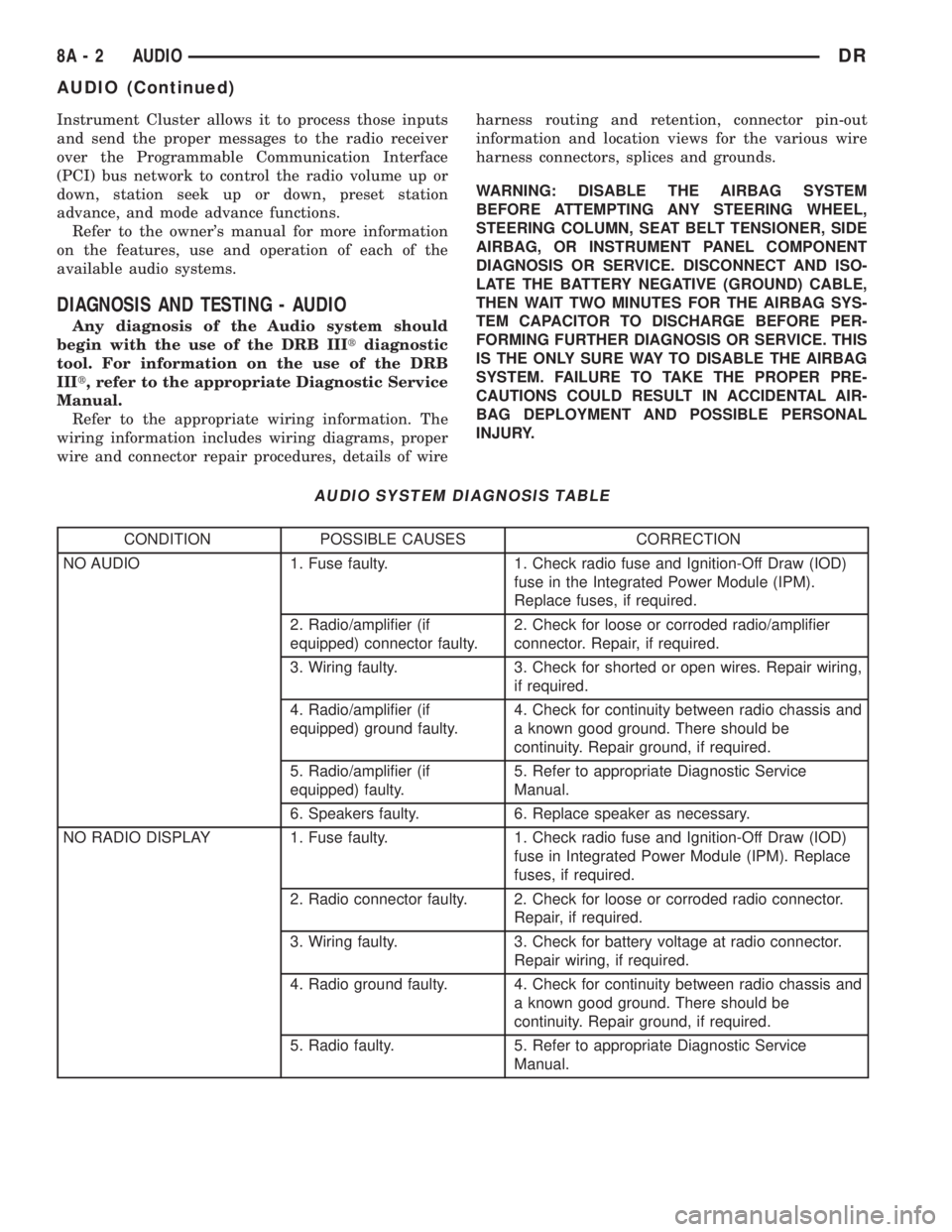
AUDIO SYSTEM DIAGNOSIS TABLE
CONDITION POSSIBLE CAUSES CORRECTION
NO AUDIO 1. Fuse faulty. 1. Check radio fuse and Ignition-Off Draw (IOD)
fuse in the Integrated Power Module (IPM).
Replace fuses, if required.
2. Radio/amplifier (if
equipped) connector faulty.2. Check for loose or corroded radio/amplifier
connector. Repair, if required.
3. Wiring faulty. 3. Check for shorted or open wires. Repair wiring,
if required.
4. Radio/amplifier (if
equipped) ground faulty.4. Check for continuity between radio chassis and
a known good ground. There should be
continuity. Repair ground, if required.
5. Radio/amplifier (if
equipped) faulty.5. Refer to appropriate Diagnostic Service
Manual.
6. Speakers faulty. 6. Replace speaker as necessary.
NO RADIO DISPLAY 1. Fuse faulty. 1. Check radio fuse and Ignition-Off Draw (IOD)
fuse in Integrated Power Module (IPM). Replace
fuses, if required.
2. Radio connector faulty. 2. Check for loose or corroded radio connector.
Repair, if required.
3. Wiring faulty. 3. Check for battery voltage at radio connector.
Repair wiring, if required.
4. Radio ground faulty. 4. Check for continuity between radio chassis and
a known good ground. There should be
continuity. Repair ground, if required.
5. Radio faulty. 5. Refer to appropriate Diagnostic Service
Manual.
8A - 2 AUDIODR
AUDIO (Continued)
Page 373 of 2895
INSTALLATION
BED TO CAB
(1) Install the ground strap and retaining bolts.
Tighten to 5 N´m (45 in. lbs.).
(2) Connect the battery negative cable.
ENGINE TO HEAT SHIELD
(1) Install the retaining nut and ground strap to
the plenum. Tighten to 8 N´m (70 in. lbs.).
(2) Install the retaining bolt and ground strap to
the engine cylinder heads. Tighten to 12 N´m (106 in.
lbs.).
(3) Connect the battery negative cable.
REMOTE SWITCHES
DESCRIPTION
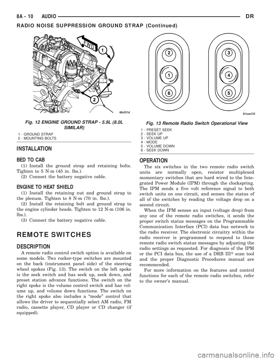
A remote radio control switch option is available on
some models. Two rocker-type switches are mounted
on the back (instrument panel side) of the steering
wheel spokes (Fig. 13). The switch on the left spoke
is the seek switch and has seek up, seek down, and
preset station advance functions. The switch on the
right spoke is the volume control switch and has vol-
ume up, and volume down functions. The switch on
the right spoke also includes a ªmodeº control that
allows the driver to sequentially select AM radio, FM
radio, cassette player, CD player or CD changer (if
equipped).
OPERATION
The six switches in the two remote radio switch
units are normally open, resistor multiplexed
momentary switches that are hard wired to the Inte-
grated Power Module (IPM) through the clockspring.
The IPM sends a five volt reference signal to both
switch units on one circuit, and senses the status of
all of the switches by reading the voltage drop on a
second circuit.
When the IPM senses an input (voltage drop) from
any one of the remote radio switches, it sends the
proper switch status messages on the Programmable
Communication Interface (PCI) data bus network to
the radio receiver. The electronic circuitry within the
radio receiver is programmed to respond to these
remote radio switch status messages by adjusting the
radio settings as requested. For diagnosis of the IPM
or the PCI data bus, the use of a DRB IIItscan tool
and the proper Diagnostic Procedures manual are
recommended.
For more information on the features and control
functions for each of the remote radio switches, refer
to the owner's manual.
Fig. 12 ENGINE GROUND STRAP - 5.9L (8.0L
SIMILAR)
1 - GROUND STRAP
2 - MOUNTING BOLTS
Fig. 13 Remote Radio Switch Operational View
1 - PRESET SEEK
2 - SEEK UP
3 - VOLUME UP
4 - MODE
5 - VOLUME DOWN
6 - SEEK DOWN
8A - 10 AUDIODR
RADIO NOISE SUPPRESSION GROUND STRAP (Continued)
Page 389 of 2895
POWERTRAIN CONTROL
MODULE
DESCRIPTION
DESCRIPTION - PCM
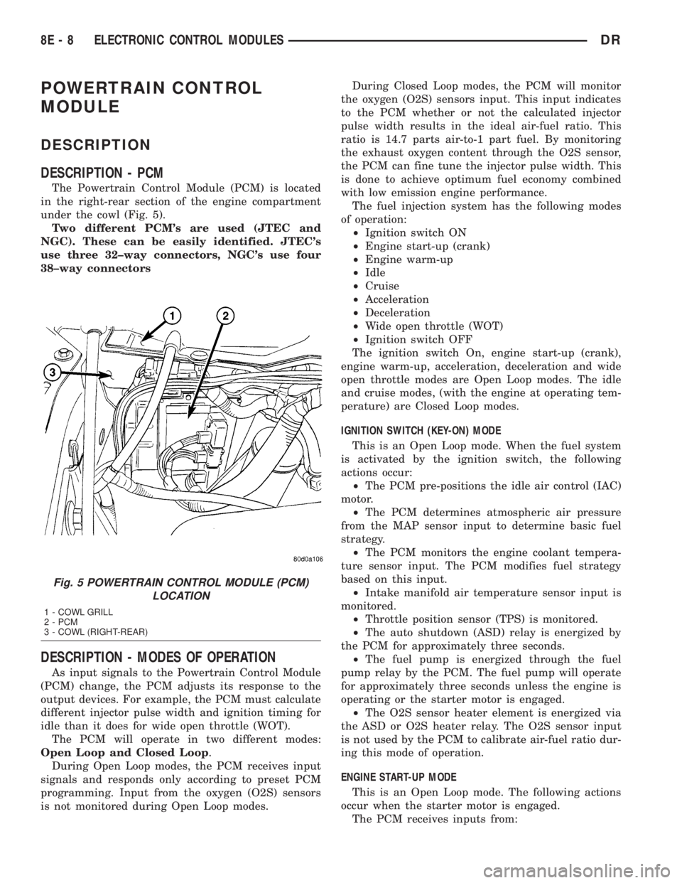
The Powertrain Control Module (PCM) is located
in the right-rear section of the engine compartment
under the cowl (Fig. 5).
Two different PCM's are used (JTEC and
NGC). These can be easily identified. JTEC's
use three 32±way connectors, NGC's use four
38±way connectors
DESCRIPTION - MODES OF OPERATION
As input signals to the Powertrain Control Module
(PCM) change, the PCM adjusts its response to the
output devices. For example, the PCM must calculate
different injector pulse width and ignition timing for
idle than it does for wide open throttle (WOT).
The PCM will operate in two different modes:
Open Loop and Closed Loop.
During Open Loop modes, the PCM receives input
signals and responds only according to preset PCM
programming. Input from the oxygen (O2S) sensors
is not monitored during Open Loop modes.During Closed Loop modes, the PCM will monitor
the oxygen (O2S) sensors input. This input indicates
to the PCM whether or not the calculated injector
pulse width results in the ideal air-fuel ratio. This
ratio is 14.7 parts air-to-1 part fuel. By monitoring
the exhaust oxygen content through the O2S sensor,
the PCM can fine tune the injector pulse width. This
is done to achieve optimum fuel economy combined
with low emission engine performance.
The fuel injection system has the following modes
of operation:
²Ignition switch ON
²Engine start-up (crank)
²Engine warm-up
²Idle
²Cruise
²Acceleration
²Deceleration
²Wide open throttle (WOT)
²Ignition switch OFF
The ignition switch On, engine start-up (crank),
engine warm-up, acceleration, deceleration and wide
open throttle modes are Open Loop modes. The idle
and cruise modes, (with the engine at operating tem-
perature) are Closed Loop modes.
IGNITION SWITCH (KEY-ON) MODE
This is an Open Loop mode. When the fuel system
is activated by the ignition switch, the following
actions occur:
²The PCM pre-positions the idle air control (IAC)
motor.
²The PCM determines atmospheric air pressure
from the MAP sensor input to determine basic fuel
strategy.
²The PCM monitors the engine coolant tempera-
ture sensor input. The PCM modifies fuel strategy
based on this input.
²Intake manifold air temperature sensor input is
monitored.
²Throttle position sensor (TPS) is monitored.
²The auto shutdown (ASD) relay is energized by
the PCM for approximately three seconds.
²The fuel pump is energized through the fuel
pump relay by the PCM. The fuel pump will operate
for approximately three seconds unless the engine is
operating or the starter motor is engaged.
²The O2S sensor heater element is energized via
the ASD or O2S heater relay. The O2S sensor input
is not used by the PCM to calibrate air-fuel ratio dur-
ing this mode of operation.
ENGINE START-UP MODE
This is an Open Loop mode. The following actions
occur when the starter motor is engaged.
The PCM receives inputs from:
Fig. 5 POWERTRAIN CONTROL MODULE (PCM)
LOCATION
1 - COWL GRILL
2 - PCM
3 - COWL (RIGHT-REAR)
8E - 8 ELECTRONIC CONTROL MODULESDR
Page 482 of 2895
(6)If necessary, install throttle body air tube or box.
KNOCK SENSOR
DESCRIPTION
The sensors are used only with 3.7L V-6, 4.7L V-8
and 5.7L V-8 engines. On 3.7L V-6 and 4.7L V-8
engines, the 2 knock sensors are bolted into the cyl-
inder block under the intake manifold.
On 5.7L V-8 engines, 2 knock sensors are also
used. These are bolted into each side of the cylinder
block (outside) under the exhaust manifold.
OPERATION
3.7L V-6 / 4.7L V-8 / 5.7L V-8 Engines Only
Two knock sensors are used; one for each cylinder
bank. When the knock sensor detects a knock in one
of the cylinders on the corresponding bank, it sends
an input signal to the Powertrain Control Module
(PCM). In response, the PCM retards ignition timing
for all cylinders by a scheduled amount.
Knock sensors contain a piezoelectric material
which constantly vibrates and sends an input voltage
(signal) to the PCM while the engine operates. As the
intensity of the crystal's vibration increases, the
knock sensor output voltage also increases.The voltage signal produced by the knock sensor
increases with the amplitude of vibration. The PCM
receives the knock sensor voltage signal as an input.
If the signal rises above a predetermined level, the
PCM will store that value in memory and retard
ignition timing to reduce engine knock. If the knock
sensor voltage exceeds a preset value, the PCM
retards ignition timing for all cylinders. It is not a
selective cylinder retard.
The PCM ignores knock sensor input during engine
idle conditions. Once the engine speed exceeds a
specified value, knock retard is allowed.
Knock retard uses its own short term and long
term memory program.
Long term memory stores previous detonation
information in its battery-backed RAM. The maxi-
mum authority that long term memory has over tim-
ing retard can be calibrated.
Short term memory is allowed to retard timing up
to a preset amount under all operating conditions (as
long as rpm is above the minimum rpm) except at
Wide Open Throttle (WOT). The PCM, using short
term memory, can respond quickly to retard timing
when engine knock is detected. Short term memory
is lost any time the ignition key is turned off.
NOTE: Over or under tightening the sensor mount-
ing bolts will affect knock sensor performance, pos-
sibly causing improper spark control. Always use
the specified torque when installing the knock sen-
sors.
REMOVAL
3.7L V-6 / 4.7L V-8
The 2 knock sensors are bolted into the cylinder
block under the intake manifold (Fig. 39). or (Fig.
40).
NOTE: The left sensor is identified by an identifica-
tion tag (LEFT). It is also identified by a larger bolt
head. The Powertrain Control Module (PCM) must
have and know the correct sensor left/right posi-
tions. Do not mix the sensor locations.
(1) Disconnect knock sensor dual pigtail harness
from engine wiring harness. This connection is made
near rear of engine.
(2) Remove intake manifold. Refer to Engine sec-
tion.
(3) Remove sensor mounting bolts (Fig. 39), or
(Fig. 40). Note foam strip on bolt threads. This foam
is used only to retain the bolts to sensors for plant
assembly. It is not used as a sealant. Do not apply
any adhesive, sealant or thread locking compound to
these bolts.
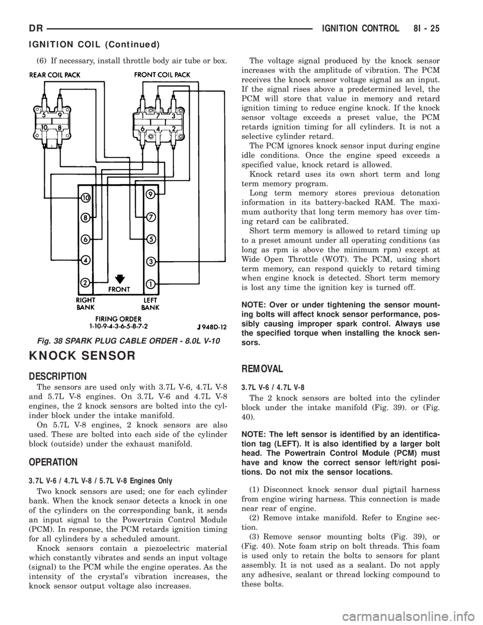
Fig. 38 SPARK PLUG CABLE ORDER - 8.0L V-10
DRIGNITION CONTROL 8I - 25
IGNITION COIL (Continued)
Page 497 of 2895
cluster illumination lamps and provide electronic
headlamp low beam and park lamp request messages
to the Front Control Module (FCM) located on the
Integrated Power Module (IPM) for default exterior
lamp operation. The FCM will also provide default
park lamp and headlamp low beam operation and the
EMIC will turn on the cluster illumination lamps if
there is a failure of the electronic data bus commu-
nication between the EMIC and the FCM.
²Heated Seat Control- The EMIC monitors
inputs from the ignition switch and electronic engine
speed messages from the Powertrain Control Module
(PCM) to control a high side driver output to the
heated seat switch Light Emitting Diode (LED) indi-
cators. This input allows the heated seat switches to
wake up the heated seat module if the switch is actu-
ated. The EMIC will de-energize the heated seat
switch LED indicators, which deactivates the heated
seat system, if the ignition switch is turned to any
position except On or Start, or if the engine speed
message indicates zero. (Refer to 8 - ELECTRICAL/
HEATED SEATS - DESCRIPTION).
²Interior Lamp Load Shedding- The EMIC
provides a battery saver feature which will automat-
ically turn off all interior lamps that remain on after
a timed interval of about fifteen minutes.
²Interior Lamps - Enhanced Accident
Response- The EMIC monitors inputs from the Air-
bag Control Module (ACM) and the Powertrain Con-
trol Module (PCM) to automatically turn on the
interior lighting after an airbag deployment event
ten seconds after the vehicle speed is zero. The inte-
rior lighting remains illuminated until the ignition
switch is turned to the Off position, at which time
the interior lighting returns to normal operation and
control. This feature, like all other enhanced accident
response features, is dependent upon a functional
vehicle electrical system following the vehicle impact
event.
²Interior Lighting Control- The EMIC moni-
tors inputs from the interior lighting switch, the door
ajar switches, the cargo lamp switch, the reading
lamp switches, and the Remote Keyless Entry (RKE)
module to provide courtesy lamp control. This
includes support for timed illuminated entry with
theater-style fade-to-off and courtesy illumination
defeat features.
²Lamp Out Indicator Control- The EMIC
monitors electronic lamp outage messages from the
Front Control Module (FCM) located on the Inte-
grated Power Module (IPM) in order to provide lamp
out indicator control for the headlamps (low and high
beams), turn signal lamps, and the brake lamps
(excluding CHMSL).
²Panel Lamps Dimming Control- The EMIC
provides a hard wired 12-volt Pulse-Width Modulated(PWM) output that synchronizes the dimming level
of all panel lamps dimmer controlled lamps with that
of the cluster illumination lamps.
²Parade Mode- The EMIC provides a parade
mode (also known as funeral mode) that allows all
Vacuum-Fluorescent Display (VFD) units in the vehi-
cle to be illuminated at full (daytime) intensity while
driving during daylight hours with the exterior
lamps turned on.
²Power Locks- The EMIC monitors inputs from
the power lock switches and the Remote Keyless
Entry (RKE) receiver module (optional) to provide
control of the power lock motors through high side
driver outputs to the power lock motors. This
includes support for rolling door locks (also known as
automatic door locks), automatic door unlock, a door
lock inhibit mode, and central locking (with the
optional Vehicle Theft Security System only). (Refer
to 8 - ELECTRICAL/POWER LOCKS - DESCRIP-
TION).
²Remote Keyless Entry- The EMIC supports
the optional Remote Keyless Entry (RKE) system fea-
tures, including support for the RKE Lock, Unlock
(with optional driver-door-only unlock, and unlock-
all-doors), Panic, audible chirp, optical chirp, illumi-
nated entry modes, an RKE programming mode, as
well as optional Vehicle Theft Security System
(VTSS) arming (when the proper VTSS arming con-
ditions are met) and disarming.
²Remote Radio Switch Interface- The EMIC
monitors inputs from the optional remote radio
switches and then provides the appropriate electronic
data bus messages to the radio to select the radio
operating mode, volume control, preset station scan
and station seek features.
²Rolling Door Locks- The EMIC provides sup-
port for the power lock system rolling door locks fea-
ture (also known as automatic door locks). This
feature will automatically lock all unlocked doors
each time the vehicle speed reaches twenty-four kilo-
meters-per-hour (fifteen miles-per-hour) and, follow-
ing an automatic lock event, will automatically
unlock all doors once the ignition is turned to the Off
position and the driver side front door is opened.
²Turn Signal & Hazard Warning Lamp Con-
trol- The EMIC provides electronic turn and hazard
lamp request messages to the Front Control Module
(FCM) located on the Integrated Power Module (IPM)
for turn and hazard lamp control. The EMIC also
provides an audible click at one of two rates to emu-
late normal and bulb out turn or hazard flasher oper-
ation based upon electronic lamp outage messages
from the FCM, and provides an audible turn signal
on chime warning if a turn is signalled continuously
for more than about 1.6 kilometers (one mile) and
8J - 4 INSTRUMENT CLUSTERDR
INSTRUMENT CLUSTER (Continued)
Page 501 of 2895
dles at several predetermined calibration points
across the gauge faces, and illuminating all segments
of the odometer/trip odometer and gear selector indi-
cator Vacuum-Fluorescent Display (VFD) units.
(Refer to 8 - ELECTRICAL/INSTRUMENT CLUS-
TER - DIAGNOSIS AND TESTING). See the owner's
manual in the vehicle glove box for more information
on the features, use and operation of the EMIC.
GAUGES
All gauges receive battery current through the
EMIC circuitry only when the ignition switch is in
the On or Start positions. With the ignition switch in
the Off position battery current is not supplied to
any gauges, and the EMIC circuitry is programmed
to move all of the gauge needles back to the low end
of their respective scales. Therefore, the gauges do
not accurately indicate any vehicle condition unless
the ignition switch is in the On or Start positions.
All of the EMIC gauges are air core magnetic
units. Two fixed electromagnetic coils are located
within each gauge. These coils are wrapped at right
angles to each other around a movable permanent
magnet. The movable magnet is suspended within
the coils on one end of a pivot shaft, while the gauge
needle is attached to the other end of the shaft. One
of the coils has a fixed current flowing through it to
maintain a constant magnetic field strength. Current
flow through the second coil changes, which causes
changes in its magnetic field strength. The current
flowing through the second coil is changed by the
EMIC circuitry in response to messages received over
the PCI data bus. The gauge needle moves as the
movable permanent magnet aligns itself to the
changing magnetic fields created around it by the
electromagnets.
The gauges are diagnosed using the EMIC self-di-
agnostic actuator test. (Refer to 8 - ELECTRICAL/
INSTRUMENT CLUSTER - DIAGNOSIS AND
TESTING). Proper testing of the PCI data bus and
the electronic data bus message inputs to the EMIC
that control each gauge require the use of a DRBIIIt
scan tool. Refer to the appropriate diagnostic infor-
mation. Specific operation details for each gauge may
be found elsewhere in this service information.
VACUUM-FLUORESCENT DISPLAYS
The Vacuum-Fluorescent Display (VFD) units are
soldered to the EMIC electronic circuit board. With
the ignition switch in the Off or Accessory positions,
the odometer display is activated when the driver
door is opened (Rental Car mode) and is deactivated
when the driver door is closed. Otherwise, both dis-
play units are active when the ignition switch is in
the On or Start positions, and inactive when the igni-
tion switch is in the Off or Accessory positions.The illumination intensity of the VFD units is con-
trolled by the EMIC circuitry based upon an input
from the headlamp switch and a dimming level input
received from the headlamp dimmer switch. The
EMIC synchronizes the illumination intensity of
other VFD units with that of the units in the EMIC
by sending electronic dimming level messages to
other electronic modules in the vehicle over the PCI
data bus.
The EMIC VFD units have several display capabil-
ities including odometer, trip odometer, engine hours,
gear selector indication (PRNDL) for models with an
automatic transmission, several warning or reminder
indications, and various diagnostic information when
certain fault conditions exist. An odometer/trip odom-
eter switch on the EMIC circuit board is used to con-
trol some of the display modes. This switch is
actuated manually by depressing the odometer/trip
odometer switch button that extends through the
lower edge of the cluster lens, just left of the tachom-
eter. Actuating this switch momentarily with the
ignition switch in the On position will toggle the
VFD between the odometer and trip odometer modes.
Depressing the switch button for about two seconds
while the VFD is in the trip odometer mode will
reset the trip odometer value to zero. While in the
odometer mode with the ignition switch in the On
position and the engine not running, depressing this
switch for about six seconds will display the engine
hours information. Holding this switch depressed
while turning the ignition switch from the Off posi-
tion to the On position will initiate the EMIC self-di-
agnostic actuator test. Refer to the appropriate
diagnostic information for additional details on this
VFD function. The EMIC microprocessor remembers
which display mode is active when the ignition
switch is turned to the Off position, and returns the
VFD display to that mode when the ignition switch is
turned On again.
The VFD units are diagnosed using the EMIC self-
diagnostic actuator test. (Refer to 8 - ELECTRICAL/
INSTRUMENT CLUSTER - DIAGNOSIS AND
TESTING). Proper testing of the PCI data bus and
the electronic data bus message inputs to the EMIC
that control some of the VFD functions requires the
use of a DRBIIItscan tool. Refer to the appropriate
diagnostic information. Specific operation details for
the odometer, the trip odometer, the gear selector
indicator and the various warning and reminder indi-
cator functions of the VFD may be found elsewhere
in this service information.
INDICATORS
Indicators are located in various positions within
the EMIC and are all connected to the EMIC elec-
tronic circuit board. The cargo lamp indicator, door
8J - 8 INSTRUMENT CLUSTERDR
INSTRUMENT CLUSTER (Continued)