service interval DODGE RAM 2003 Service Repair Manual
[x] Cancel search | Manufacturer: DODGE, Model Year: 2003, Model line: RAM, Model: DODGE RAM 2003Pages: 2895, PDF Size: 83.15 MB
Page 19 of 2895
MAINTENANCE SCHEDULES
DESCRIPTION
Maintenance Schedule Information not included in
this section, is located in the appropriate Owner's
Manual.
There are two maintenance schedules that show
therequiredservice for your vehicle.
First is ScheduleªBº. It is for vehicles that are
operated under the conditions that are listed below
and at the beginning of the schedule.
²Day or night temperatures are below 0É C (32É
F).
²Stop and go driving.
²Extensive engine idling.
²Driving in dusty conditions.
²Short trips of less than 16 km (10 miles).
²More than 50% of your driving is at sustained
high speeds during hot weather, above 32É C (90É F).
²Trailer towing.
²Taxi, police, or delivery service (commercial ser-
vice).
²Off-road or desert operation.
²If equipped for and operating with E-85
(ethanol) fuel.
NOTE: Most vehicles are operated under the condi-
tions listed for Schedule(B(.
Second is ScheduleªAº. It is for vehicles that are
not operated under any of the conditions listed under
Schedule9B9.
Use the schedule that best describes your driving
conditions. Where time and mileage are listed, follow
the interval that occurs first.
CAUTION: Failure to perform the required mainte-
nance items may result in damage to the vehicle.
At Each Stop for Fuel
²Check the engine oil level about 5 minutes after
a fully warmed engine is shut off. Checking the oil
level while the vehicle is on level ground will
improve the accuracy of the oil level reading. Add oil
only when the level is at or below the ADD or MIN
mark.
²Check the windshield washer solvent and add if
required.
Once a Month
²Check tire pressure and look for unusual wear
or damage.
²Inspect the battery and clean and tighten the
terminals as required.
²Check the fluid levels of coolant reservoir, brake
master cylinder, power steering and transmission
and add as needed.
²Check all lights and all other electrical items for
correct operation.
At Each Oil Change
²Change the engine oil filter.
²Inspect the exhaust system.
²Inspect the brake hoses.
²Inspect the CV joints (if equipped) and front sus-
pension components.
²Check the automatic transmission fluid level.
²Check the manual transmission fluid level.
²Check the coolant level, hoses, and clamps.
²Rotate the tires at each oil change interval
shown on Schedule ªAº 10 000 km (6,000 miles) or
every other interval shown on Schedule ªBº 10 000
km (6,000 miles).
Schedule ªBº
Follow schedule ªBº if you usually operate your
vehicle under one or more of the following conditions.
²Day or night temperatures are below 0É C (32É
F).
²Stop and go driving.
²Extensive engine idling.
²Driving in dusty conditions.
²Short trips of less than 16 km (10 miles).
²More than 50% of your driving is at sustained
high speeds during hot weather, above 32É C (90É F).
²Trailer towing.
²Taxi, police, or delivery service (commercial ser-
vice).
²Off-road or desert operation.
²If equipped for and operating with E-85
(ethanol) fuel.
0 - 6 LUBRICATION & MAINTENANCEDR
Page 380 of 2895
CHIME/BUZZER
TABLE OF CONTENTS
page page
CHIME/BUZZER
DESCRIPTION..........................1
OPERATION............................1DIAGNOSIS AND TESTING - CHIME
CONDITIONS..........................2
CHIME/BUZZER
DESCRIPTION
The chime module is located within the instrument
cluster and is not serviceable. The chime system pro-
vides the driver with warning chimes for:
²Air Bag
²Seat Belt
²Low Fuel
²Door Ajar
²Low Wash
²Park Brake
²Over Speed
²Turn Signal On
²Key-In Ignition
²Exterior Lamps ON
²Warning Lamp Announcement
²Transmission Over Temperature
OPERATION
FASTEN SEAT BELT
The seat belt reminder system uses both visual
and audible signals. The Instrument Cluster moni-
tors the driver seat belt buckle switch. When the
ignition switch transitions from OFF to RUN and the
driver seat belt has not been buckled, the Instrument
Cluster will illuminate the seat belt indicator lamp
and sound the chime. The system will always illumi-
nate the seat belt reminder lamp for four to eight
seconds when the ignition switch is turned to the ON
position. The CHIME will sound during the same
time interval if the driver's seat belt is not fastened.
The warning lamp will remain illuminated as long as
the seat belt remains unbuckled, and the ignition
switch is in the RUN position. Passenger seat belts
are not connected to the system.
HEADLAMPS REMINDER
The Instrument Cluster monitors the multiplex
headlamp switch. The headlamp audible warning will
alert the driver that the exterior lamps have been
left on. If the ignition switch is left off, the driver's
door open, and the headlamp switch is in the parklamp or headlamp position, the chime will sound
until the headlamp switch is turned off, the door is
closed or the battery protection time out expires.
KEY IN IGNITION REMINDER
The Instrument Cluster monitors the ignition
switch. The chime will activate if the drivers door is
opened and the key is in the ignition switch, with the
ignition switch in either the OFF, LOCK, or the
accessory (ACC) position. The chime will continue
until the key is removed from the ignition switch or
the door is closed.
DOOR AJAR CHIME
The Instrument Cluster monitors the door ajar
switches. A chime will sound once when the door is
opened, the ignition is in RUN position and vehicle
speed is present.
TURN SIGNAL ON
The Instrument Cluster monitors the multiplex
multifunction switch. The instrument cluster shall
remind the driver that either turn signal has been
left on by a continuous chime after the turn signal
indicator is left ON for 1.0 miles and the vehicle
speed is 15 mph or greater.
LOW FUEL REMINDER
When the fuel level drops to approximately 1/8
tank, the fuel symbol will light and a single chime
will sound. The light will remain on until fuel is
added.
OVER SPEED
During any ignition ON, the Instrument Cluster
maintains the most recently received speed. If the
vehicle speed exceeds a preprogramed limit set in the
instrument cluster it will activate a single chime.
WARNING LAMP ANNOUNCEMENT
The Instrument Cluster monitors critical engine
and transmission system parameters. If any of the
systems are out of their operating parameters, the
instrument cluster will illuminate a lamp and acti-
vate and audible chime.
DRCHIME/BUZZER 8B - 1
Page 416 of 2895
Turn on the headlamps for fifteen seconds, then
allow up to five minutes for the battery voltage to
stabilize.
(2) Disconnect and isolate both battery cables, neg-
ative cable first.
(3) Using a voltmeter connected to the battery
posts (see the instructions provided by the manufac-
turer of the voltmeter), measure the open-circuit volt-
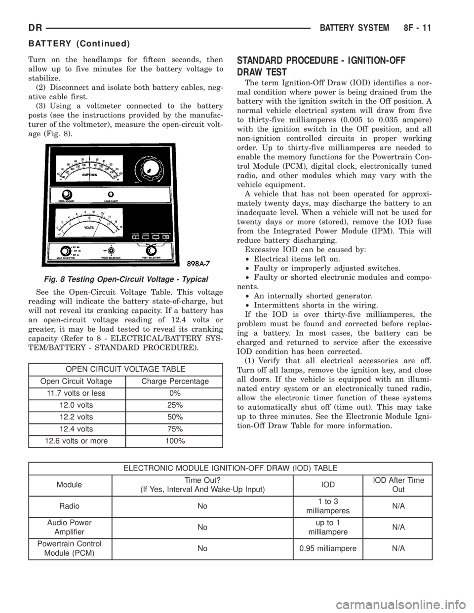
age (Fig. 8).
See the Open-Circuit Voltage Table. This voltage
reading will indicate the battery state-of-charge, but
will not reveal its cranking capacity. If a battery has
an open-circuit voltage reading of 12.4 volts or
greater, it may be load tested to reveal its cranking
capacity (Refer to 8 - ELECTRICAL/BATTERY SYS-
TEM/BATTERY - STANDARD PROCEDURE).
OPEN CIRCUIT VOLTAGE TABLE
Open Circuit Voltage Charge Percentage
11.7 volts or less 0%
12.0 volts 25%
12.2 volts 50%
12.4 volts 75%
12.6 volts or more 100%
STANDARD PROCEDURE - IGNITION-OFF
DRAW TEST
The term Ignition-Off Draw (IOD) identifies a nor-
mal condition where power is being drained from the
battery with the ignition switch in the Off position. A
normal vehicle electrical system will draw from five
to thirty-five milliamperes (0.005 to 0.035 ampere)
with the ignition switch in the Off position, and all
non-ignition controlled circuits in proper working
order. Up to thirty-five milliamperes are needed to
enable the memory functions for the Powertrain Con-
trol Module (PCM), digital clock, electronically tuned
radio, and other modules which may vary with the
vehicle equipment.
A vehicle that has not been operated for approxi-
mately twenty days, may discharge the battery to an
inadequate level. When a vehicle will not be used for
twenty days or more (stored), remove the IOD fuse
from the Integrated Power Module (IPM). This will
reduce battery discharging.
Excessive IOD can be caused by:
²Electrical items left on.
²Faulty or improperly adjusted switches.
²Faulty or shorted electronic modules and compo-
nents.
²An internally shorted generator.
²Intermittent shorts in the wiring.
If the IOD is over thirty-five milliamperes, the
problem must be found and corrected before replac-
ing a battery. In most cases, the battery can be
charged and returned to service after the excessive
IOD condition has been corrected.
(1) Verify that all electrical accessories are off.
Turn off all lamps, remove the ignition key, and close
all doors. If the vehicle is equipped with an illumi-
nated entry system or an electronically tuned radio,
allow the electronic timer function of these systems
to automatically shut off (time out). This may take
up to three minutes. See the Electronic Module Igni-
tion-Off Draw Table for more information.
ELECTRONIC MODULE IGNITION-OFF DRAW (IOD) TABLE
ModuleTime Out?
(If Yes, Interval And Wake-Up Input)IODIOD After Time
Out
Radio No1to3
milliamperesN/A
Audio Power
AmplifierNoup to 1
milliampereN/A
Powertrain Control
Module (PCM)No 0.95 milliampere N/A
Fig. 8 Testing Open-Circuit Voltage - Typical
DRBATTERY SYSTEM 8F - 11
BATTERY (Continued)
Page 417 of 2895
ELECTRONIC MODULE IGNITION-OFF DRAW (IOD) TABLE
ModuleTime Out?
(If Yes, Interval And Wake-Up Input)IODIOD After Time
Out
ElectroMechanical
Instrument Cluster
(EMIC)No 0.44 milliampere N/A
Combination Flasher No 0.08 milliampere N/A
(2) Determine that the underhood lamp is operat-
ing properly, then disconnect the lamp wire harness
connector or remove the lamp bulb.
(3) Disconnect the battery negative cable.
(4) Set an electronic digital multi-meter to its
highest amperage scale. Connect the multi-meter
between the disconnected battery negative cable ter-
minal clamp and the battery negative terminal post.
Make sure that the doors remain closed so that the
illuminated entry system is not activated. The multi-
meter amperage reading may remain high for up to
three minutes, or may not give any reading at all
while set in the highest amperage scale, depending
upon the electrical equipment in the vehicle. The
multi-meter leads must be securely clamped to the
battery negative cable terminal clamp and the bat-
tery negative terminal post. If continuity between the
battery negative terminal post and the negative cable
terminal clamp is lost during any part of the IOD
test, the electronic timer function will be activated
and all of the tests will have to be repeated.
(5) After about three minutes, the high-amperage
IOD reading on the multi-meter should become very
low or nonexistent, depending upon the electrical
equipment in the vehicle. If the amperage reading
remains high, remove and replace each fuse or circuit
breaker in the Integrated Power Module (IPM), one
at a time until the amperage reading becomes very
low, or nonexistent. Refer to the appropriate wiring
information in this service manual for complete Inte-
grated Power Module fuse, circuit breaker, and cir-
cuit identification. This will isolate each circuit and
identify the circuit that is the source of the high-am-
perage IOD. If the amperage reading remains high
after removing and replacing each fuse and circuit
breaker, disconnect the wire harness from the gener-
ator. If the amperage reading now becomes very low
or nonexistent, refer to Charging System for the
proper charging system diagnosis and testing proce-
dures. After the high-amperage IOD has been cor-
rected, switch the multi-meter to progressively lower
amperage scales and, if necessary, repeat the fuse
and circuit breaker remove-and-replace process to
identify and correct all sources of excessive IOD. It is
now safe to select the lowest milliampere scale of the
multi-meter to check the low-amperage IOD.CAUTION: Do not open any doors, or turn on any
electrical accessories with the lowest milliampere
scale selected, or the multi-meter may be damaged.
(6) Observe the multi-meter reading. The low-am-
perage IOD should not exceed thirty-five milliam-
peres (0.035 ampere). If the current draw exceeds
thirty-five milliamperes, isolate each circuit using the
fuse and circuit breaker remove-and-replace process
in Step 5. The multi-meter reading will drop to
within the acceptable limit when the source of the
excessive current draw is disconnected. Repair this
circuit as required; whether a wiring short, incorrect
switch adjustment, or a component failure is at fault.
STANDARD PROCEDURE - USING MICRO 420
BATTERY TESTER
Always use the Micro 420 Instruction Manual that
was supplied with the tester as a reference. If the
Instruction Manual is not available the following pro-
cedure can be used:
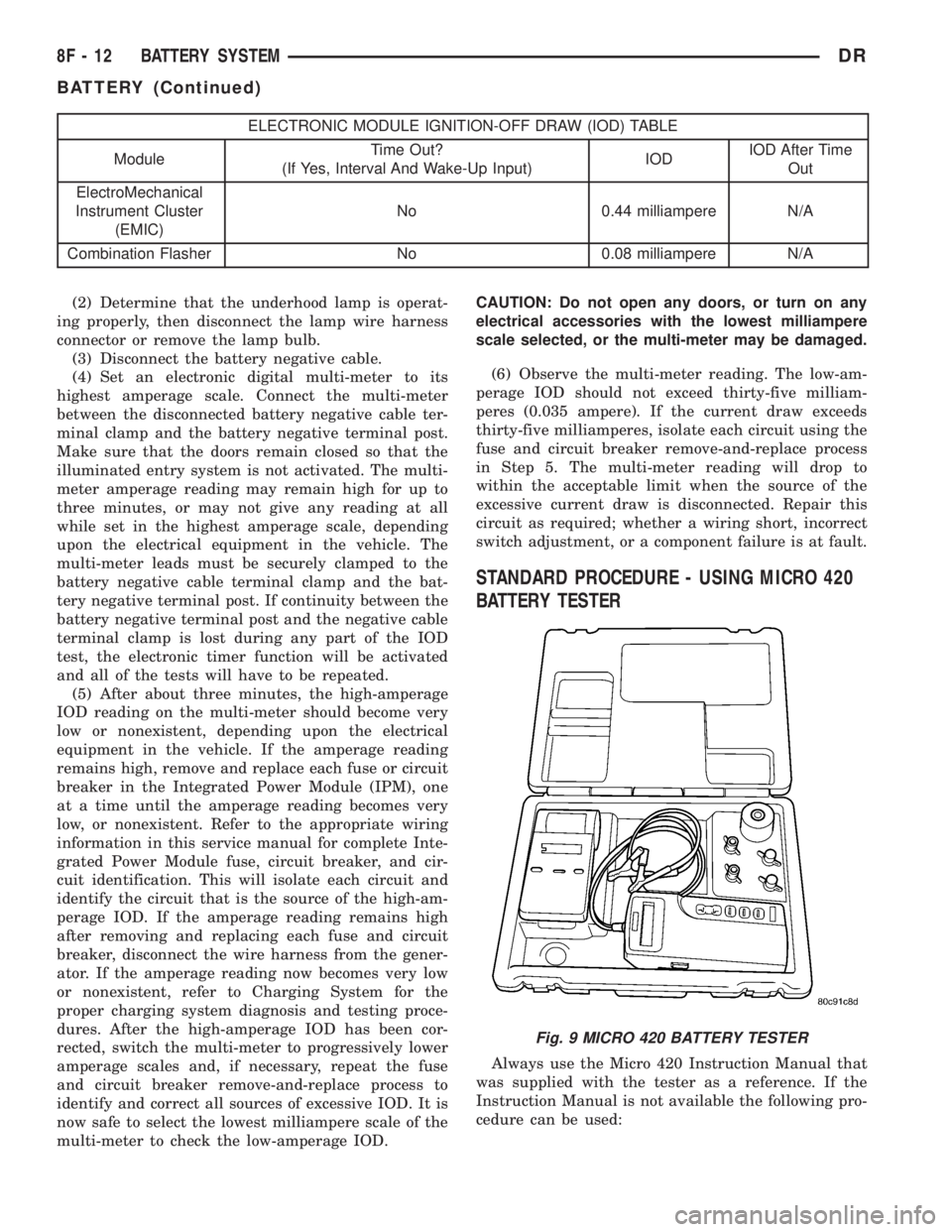
Fig. 9 MICRO 420 BATTERY TESTER
8F - 12 BATTERY SYSTEMDR
BATTERY (Continued)
Page 447 of 2895
heated mirror switch is depressed and released a sec-
ond time during the same ignition cycle, the elec-
tronic control logic and timer circuitry will
automatically turn the heated mirror system off after
a programmed time interval of about five minutes.
The heated mirror system will be shut off automati-
cally if the ignition switch is turned to the Off or
Accessory positions. After the heated mirror system
is turned On, it can also be turned off manually by
depressing and releasing the heated mirror switch a
second time.
When the heated mirror system is turned On, the
heated mirror system control logic and timer cir-
cuitry energizes the heated mirror system indicator
lamp and the heated mirror relay. When energized,
the heated mirror relay supplies fused ignition
switch output (run/start) current from a fuse in the
JB to the outside mirror heating grids located behind
the mirror glass of each of the outside rear view mir-
rors. When energized, each of the outside mirror
heating grids produces enough heat to warm the
glass of the outside rear view mirrors.
DIAGNOSIS AND TESTING - HEATED MIRROR
SYSTEM
If only one of the outside mirror heating grids is
inoperative, perform continuity checks on the circuits
and heater grid for that mirror only. If both outside
mirror heating grids are inoperative, proceed with
the heated mirror system diagnosis as follows. (Refer
to Appropriate Wiring Information).
WARNING: ON VEHICLES EQUIPPED WITH AIR-
BAGS, DISABLE THE AIRBAG SYSTEM BEFORE
ATTEMPTING ANY STEERING WHEEL, STEERING
COLUMN, OR INSTRUMENT PANEL COMPONENT
DIAGNOSIS OR SERVICE. DISCONNECT AND ISO-
LATE THE BATTERY NEGATIVE (GROUND) CABLE,
THEN WAIT TWO MINUTES FOR THE AIRBAG SYS-
TEM CAPACITOR TO DISCHARGE BEFORE PER-
FORMING FURTHER DIAGNOSIS OR SERVICE. THIS
IS THE ONLY SURE WAY TO DISABLE THE AIRBAG
SYSTEM. FAILURE TO TAKE THE PROPER PRE-
CAUTIONS COULD RESULT IN ACCIDENTAL AIR-
BAG DEPLOYMENT AND POSSIBLE PERSONAL
INJURY.The operation of the heated mirror system can be
confirmed in one of the following manners:
1. Turn the ignition switch to the On position.
While monitoring the instrument panel voltmeter,
momentarily depress and release the heated mirror
switch. When the heated mirror system is turned On,
a distinct voltmeter needle deflection should be
noted.
2. Turn the ignition switch to the On position.
Momentarily depress and release the heated mirror
switch to turn the heated mirror system On. The
heated mirror operation can be checked by feeling
the outside rear view mirror glass. A distinct differ-
ence in temperature between the unheated and
heated mirror glass can be detected within three to
four minutes of system operation.
The above checks will confirm system operation.
Illumination of the heated mirror system indicator
lamp means that there is electrical current available
at the heated mirror relay, but does not confirm that
the electrical current is reaching the outside mirror
heating grids.
If the heated mirror system does not operate, the
problem should be isolated in the following manner:
(1) Confirm that the ignition switch is in the On
position.
(2) Check the fuses in the Power Distribution Cen-
ter (PDC) and in the Junction Block (JB). The fuses
must be tight in their receptacles and all electrical
connections must be secure.
When the above steps have been completed and
both outside mirror heating grids are still inopera-
tive, one or more of the following is faulty:
²Heated mirror switch, electronic control logic
and timer circuitry, and heated mirror relay.
²Heated mirror wire harness circuits or connec-
tors.
²Outside mirror heating grid (both mirror grids
would have to be faulty).
If turning On the heated mirror system produces a
severe voltmeter deflection or fuse failures, check for
a shorted circuit between the output of the heated
mirror relay and the outside mirror heating grids.
8G - 2 HEATED MIRRORSDR
HEATED MIRRORS (Continued)
Page 505 of 2895
ACTUATOR TEST
WARNING: ON VEHICLES EQUIPPED WITH AIR-
BAGS, DISABLE THE SUPPLEMENTAL RESTRAINT
SYSTEM BEFORE ATTEMPTING ANY STEERING
WHEEL, STEERING COLUMN, DRIVER AIRBAG,
PASSENGER AIRBAG, SEAT BELT TENSIONER,
SIDE CURTAIN AIRBAG, OR INSTRUMENT PANEL
COMPONENT DIAGNOSIS OR SERVICE. DISCON-
NECT AND ISOLATE THE BATTERY NEGATIVE
(GROUND) CABLE, THEN WAIT TWO MINUTES FOR
THE SYSTEM CAPACITOR TO DISCHARGE BEFORE
PERFORMING FURTHER DIAGNOSIS OR SERVICE.
THIS IS THE ONLY SURE WAY TO DISABLE THE
SUPPLEMENTAL RESTRAINT SYSTEM. FAILURE TO
TAKE THE PROPER PRECAUTIONS COULD
RESULT IN ACCIDENTAL AIRBAG DEPLOYMENT
AND POSSIBLE PERSONAL INJURY.
The instrument cluster actuator test will put the
instrument cluster into its self-diagnostic mode. In
this mode the instrument cluster can perform a self-
diagnostic test that will confirm that the instrument
cluster circuitry, the gauges, and the indicators are
capable of operating as designed. During the actuator
test the instrument cluster circuitry will position
each of the gauge needles at various calibration
points, illuminate all of the segments in the Vacuum
Fluorescent Display (VFD) units, turn all of the indi-
cators on and off again, display any Diagnostic Trou-
ble Code (DTC) information, and display the number
of ignition key cycles that have occurred since the
DTC was detected. It is suggested that a note pad
and pencil be used to write down any fault informa-
tion that is displayed during the test for reference.
Successful completion of the actuator test will con-
firm that the instrument cluster is operational. How-
ever, there may still be a problem with the PCI data
bus, the Powertrain Control Module (PCM), the
Engine Control Module (ECM), the Front Control
Module (FCM), the Transmission Control Module
(TCM), the Transfer Case Control Module (TCCM),
the Airbag Control Module (ACM), the Controller
Anti-lock Brake (CAB), or the inputs to one of these
electronic control modules. Use a DRBIIItscan toolto diagnose these components. Refer to the appropri-
ate diagnostic information.
(1) Begin the test with the ignition switch in the
Off position.
(2) Depress the odometer/trip odometer switch but-
ton.
(3) While still holding the odometer/trip odometer
switch button depressed, turn the ignition switch to
the On position, but do not start the engine.
(4) Release the odometer/trip odometer switch but-
ton.
(5) The instrument cluster will simultaneously
illuminate all of the operational segments in both
VFD units, perform a bulb check of each operational
LED indicator. The VFD segments and LED indica-
tors remain illuminated as each gauge needle is
swept to several calibration points and back. If a
VFD segment or an LED indicator fails to illuminate,
or if a gauge needle fails to sweep through the cali-
bration points and back during this test, the instru-
ment cluster must be replaced. Following these tests,
the actuator test will proceed as described in Step 6.
(6) The text ªC Codeº is displayed in the odometer
VFD for about three seconds. If there is no stored
fault information, the display will show two pairs of
zeroes in the format ª00º ª00º, which indicate that
the display of fault information is done. If there is
stored fault information, two sets of two-digit alpha
and alpha-numeric fault codes will appear in the
odometer display for a three second interval. The
first pair of digits represents a Diagnostic Trouble
Code (DTC), or fault code for the instrument cluster.
The second pair of digits is a counter for the number
of ignition key cycles that have occurred since the
displayed DTC was set. The instrument cluster will
continue to display additional sets of two pairs of dig-
its at three second intervals until all of the stored
codes have been displayed, which is again signaled
by a code of ª00º ª00º. Refer to the Instrument Clus-
ter Failure Message table for a description of each
fault code that the instrument cluster displays. If an
instrument cluster fault is displayed, use a DRBIIIt
scan tool to diagnose the problem. Refer to the appro-
priate diagnostic information.
INSTRUMENT CLUSTER FAILURE MESSAGE
Fault Code Description Correction
01 Airbag warning indicator output circuit shorted. Refer to the appropriate diagnostic information.
02 Airbag warning indicator output circuit open. Refer to the appropriate diagnostic information.
03 ABS indicator output circuit shorted. Refer to the appropriate diagnostic information.
04 ABS indicator output circuit open. Refer to the appropriate diagnostic information.
05 MIL indicator output circuit shorted. Refer to the appropriate diagnostic information.
06 MIL indicator output circuit open. Refer to the appropriate diagnostic information.
8J - 12 INSTRUMENT CLUSTERDR
INSTRUMENT CLUSTER (Continued)
Page 521 of 2895
instrument cluster overlay. The dark outer layer of
the overlay prevents the indicator from being clearly
visible when the it is not illuminated. A blue Light
Emitting Diode (LED) behind the cutout in the
opaque layer of the overlay causes the icon to appear
in blue through the translucent outer layer of the
overlay when the indicator is illuminated from
behind by the LED, which is soldered onto the
instrument cluster electronic circuit board. The high
beam indicator is serviced as a unit with the instru-
ment cluster.
OPERATION
The high beam indicator gives an indication to the
vehicle operator whenever the headlamp high beams
are illuminated. This indicator is controlled by a
transistor on the instrument cluster circuit board
based upon cluster programming and a hard wired
multiplex input received by the cluster from the
headlamp beam select switch circuitry of the multi-
function switch on the washer/beam select switch
mux circuit. The high beam indicator Light Emitting
Diode (LED) is completely controlled by the instru-
ment cluster logic circuit, and that logic will allow
this indicator to operate whenever the instrument
cluster receives a battery current input on the fused
B(+) circuit. Therefore, the LED can be illuminated
regardless of the ignition switch position. The LED
only illuminates when it is provided a path to ground
by the instrument cluster transistor. The instrument
cluster will turn on the high beam indicator for the
following reasons:
²High Beam Headlamps-On Input- Each time
the cluster detects a high beam headlamps-on input
from the headlamp beam select switch circuitry of
the multi-function switch on the washer/beam select
switch mux circuit, the headlamp high beams and
the high beam indicator will be illuminated. The
headlamp high beams and the high beam indicator
remain illuminated until the cluster receives a high
beam headlamps-off input from the multi-function
switch, or until the exterior lamp load shedding (bat-
tery saver) timed interval expires, whichever occurs
first.
²Actuator Test- Each time the cluster is put
through the actuator test, the high beam indicator
will be turned on, then off again during the bulb
check portion of the test to confirm the functionality
of the LED and the cluster control circuitry.
The instrument cluster continually monitors the
headlamp switch and the multi-function switch to
determine the proper headlamp low beam and high
beam control. The instrument cluster then sends the
proper low beam and high beam lamp-on and lamp-
off messages to the Front Control Module (FCM) over
the Programmable Communications Interface (PCI)data bus and turns the high beam indicator on or off
accordingly. For further diagnosis of the high beam
indicator or the instrument cluster circuitry that con-
trols the indicator, (Refer to 8 - ELECTRICAL/IN-
STRUMENT CLUSTER - DIAGNOSIS AND
TESTING). For proper diagnosis of the headlamps, or
the headlamp switch and multi-function switch
inputs to the instrument cluster that control the high
beam indicator, a DRBIIItscan tool is required.
Refer to the appropriate diagnostic information.
LAMP OUT INDICATOR
DESCRIPTION
A lamp out indicator is standard equipment on all
instrument clusters. The lamp out indicator consists
of the words ªLAMP OUTº, which appear in the
lower portion of the odometer/trip odometer Vacuum-
Fluorescent Display (VFD) unit. The VFD is soldered
onto the cluster electronic circuit board and is visible
through a window with a smoked clear lens located
on the lower edge of the tachometer gauge dial face
of the cluster overlay. The dark lens over the VFD
prevents the indicator from being clearly visible
when it is not illuminated. The words ªLAMP OUTº
appear in an amber color and at the same lighting
level as the odometer/trip odometer information
when they are illuminated by the instrument cluster
electronic circuit board. The lamp out indicator is
serviced as a unit with the VFD in the instrument
cluster.
OPERATION
The lamp out indicator gives an indication to the
vehicle operator when an exterior lamp has failed.
This indicator is controlled by the instrument cluster
circuit board based upon cluster programming and
electronic messages received by the cluster from the
Front Control Module (FCM) over the Programmable
Communications Interface (PCI) data bus. The lamp
out indicator is completely controlled by the instru-
ment cluster logic circuit, and that logic will only
allow this indicator to operate when the instrument
cluster receives a battery current input on the fused
ignition switch output (run-start) circuit. Therefore,
the indicator will always be off when the ignition
switch is in any position except On or Start. The
indicator only illuminates when it is switched to
ground by the instrument cluster circuitry. The
instrument cluster will turn on the lamp out indica-
tor for the following reasons:
²Lamp Out Indicator Lamp-On Message-
Each time the cluster receives a lamp out indicator
lamp-on message from the FCM indicating that an
inoperative headlamp (low or high beam), turn signal
8J - 28 INSTRUMENT CLUSTERDR
HIGH BEAM INDICATOR (Continued)
Page 571 of 2895
Refer toELECTRONIC VEHICLE INFORMA-
TION CENTER PROGRAMMINGin the Standard
Procedures section of this group for more information
on the customer programmable feature options.
If the vehicle is equipped with the optional univer-
sal transmitter transceiver, the EVIC will also dis-
play messages and an icon indicating when the
universal transmitter transceiver is being trained,
which of the three transmitter buttons is transmit-
ting, and when the transceiver is cleared.
Data input for all EVIC functions, including VFD
dimming level, is received through the J1850 PCI
data bus circuit. The EVIC module uses its internal
programming and all of its data inputs to calculate
and display the requested data. If the data displayed
is incorrect, perform the self-diagnostic tests as
described in this group. If these tests prove inconclu-
sive, the use of a DRB IIItscan tool and the proper
Diagnostic Procedures manual are recommended for
further testing of the EVIC module and the J1850
PCI data bus circuit.
The EVIC module cannot be repaired, and is avail-
able for service only as a unit. If any part is faulty or
damaged, the complete EVIC module must be
replaced.
OPERATION
The Electronic Vehicle Information Center is wired
to both constant 12v and ignition switched sources of
battery current so that some of its features remain
operational at any time, while others may only oper-
ate with the ignition switch in the On position. When
the ignition switch is turned to the On position, the
EVIC module display will return to the last function
being displayed before the ignition was turned to the
Off position.
The compass/temperature display is the normal
EVIC display. With the ignition switch in the On
position, momentarily depressing and releasing the
C/T (compass/temperature) push button switch will
cause the EVIC to return to the compass/tempera-
ture display mode from any other mode. While in the
compass/temperature display mode, momentarily
depressing and releasing the Step push button will
step through the available trip computer display
options.
The EVIC trip computer features several functions
that can be reset. The functions that can be reset
are: average fuel economy, trip odometer and elapsed
time. With the ignition switch in the On position and
with one of the functions of the trip computer that
can be reset currently displayed, depressing the
Reset push button twice within three seconds will
perform a global reset, and all of the trip computer
information that can be reset will be reset to zero.
With the ignition switch in the On position and thefunction that is to be reset currently displayed,
momentarily depressing and releasing the Reset
push button once will perform a local reset, and only
the value of the displayed function will be reset to
zero. A global or local reset will only occur if the
function currently displayed is a function that can be
reset. The distance to service function can also be
reset using the local reset method, but it will reset
back to the Service Interval distance that is set in
the EVIC programmable features mode. Refer to
ELECTRONIC VEHICLE INFORMATION CEN-
TER PROGRAMMINGin the Standard Procedures
section of this group for more information on setting
the Service Interval.
For more information on the features, control func-
tions and setting procedures for the EVIC module,
see the owner's manual in the vehicle glove box.
DIAGNOSIS AND TESTING - ELECTRONIC
VEHICLE INFORMATION CENTER
Electronic Vehicle Information Center (EVIC) data
is obtained from other electronic modules (CCN,
FCM, JTEC) on the J1850 Data Bus circuit. The
EVIC will display dashes (- -) for any of the screens
it did not receive the bus messages. The label corre-
sponding to the missing information will be lit. If no
EVIC data is displayed, check the J1850 Data Bus
circuit communications and the other modules. If the
brightness level is improper check the J1850 Data
Bus circuit.
Refer to Overhead Console Diagnosis and Testing
for instructions on performing a EVIC module Self-
Diagnostic Test. The DRB IIItis recommended for
checking the J1850 Data Bus circuit and other mod-
ules. Perform the EVIC self diagnosis before replac-
ing the EVIC module.
STANDARD PROCEDURE - ELECTRONIC
VEHICLE INFORMATION CENTER
PROGRAMMING
EVIC PROGRAMMING MODE
Some vehicles are equipped with a Electronic Vehi-
cle Information Center (EVIC) equipped overhead
console. The Electronic Vehicle Information Center
(EVIC) provides the vehicle operator with a user
interface, which allows the selection of several
optional customer programmable electronic features
to suit individual preferences. The EVIC must be
placed into its programming mode in order to view or
change the programmable features. To enter the
EVIC programming mode and to view or change the
selected programmable features options, proceed as
follows:
(1) Turn the ignition switch to the On position.
8M - 8 MESSAGE SYSTEMSDR
ELECTRONIC VEHICLE INFO CENTER (Continued)
Page 572 of 2895
(2) Momentarily depress and release the Menu
push button to step through the programmable fea-
tures list. Each programmable feature and its cur-
rently selected option will appear on the EVIC
display in the sequence shown in the Programmable
Features list that follows.
(3) Momentarily depress and release the Step push
button to step through the available options for the
programmable feature being displayed.
(4) The option that last appears in the display
with a programmable feature before exiting the pro-
gramming mode, becomes the newly selected pro-
grammable feature option.
(5) The EVIC exits the programming mode and
returns to its normal operating mode when the C/T
push button is depressed or when the end of the pro-
grammable features menu list is reached, whichever
occurs first.
PROGRAMMABLE FEATURES
²LANGUAGE?- The options include English,
Francaise, Deutsch, Italiana, or Espanol. The default
is English. All EVIC display nomenclature, including
the trip computer functions, warning messages and
the programmable features appear in the selected
language.
²DISPLAY U.S. OR METRIC?- The options
include U.S. and M. The default is U.S. This feature
toggles the trip computer temperature, fuel economy
and odometer display readings between U.S. and
metric units of measure.
²SERVICE INTV. =- The options include from
3200 to 12000 kilometers in 800 kilometer incre-
ments (2000 to 6000 miles in 500 mile increments).
The default is 12000 kilometers (6000 miles). The
selected distance becomes the interval at which the
Perform Service warning message will be displayed
by the EVIC. If a new distance is selected, a second
programmable feature appears,RESET SERVICE
DISTANCE?- The options include No and Yes. The
default is Yes. When Yes is selected, the accumulated
distance since the last previous Perform Service
warning message will be reset to zero because the
service interval has been changed. When No is
selected, the distance until the next Perform Service
warning message is reduced by the accumulated dis-
tance since the last previous message.
²AUTO DOOR LOCKS?- The options include
Yes and No. The default is Yes. When Yes is selected,
all doors lock automatically when vehicle speed
reaches 25 kilometers-per-hour (15 miles-per-hour). If
YES is selected, a second programmable feature
appears,AUTO UNLOCK ON EXIT?- The options
again include Yes and No. The default is No. When
Yes is selected, following each Auto Door Lock event
all doors will automatically unlock when the driverdoor is opened, if the vehicle is stopped and the
transmission gear selector is in Park or Neutral. The
Auto Door Unlock event will only occur once follow-
ing each Auto Door Lock event.
²REMOTE UNLOCK- The options include
Driver Door 1st and All Doors. The default is Driver
Door 1st. When Diver Door 1st is selected, only the
driver door unlocks when the Unlock button of the
Remote Keyless Entry (RKE) transmitter is
depressed once. The Unlock button of the RKE trans-
mitter must be depressed twice to unlock all doors.
When All Doors is selected, all doors unlock when the
Unlock button of the RKE transmitter is depressed
once.
²SOUND HORN ON LOCK?- The options
include On and Off. The default is No. When Yes is
selected, a short horn chirp will provide an audible
confirmation when the RKE receiver recognizes a
valid Lock signal from an RKE transmitter. When No
is selected, no horn chirp will occur with the RKE
Lock event. This feature may be selected indepen-
dent of theFLASH LIGHTS WITH LOCKS?pro-
grammable feature.
²FLASH LIGHTS WITH LOCKS?- The options
include Yes and No. The default is Yes. When Yes is
selected, a single flash of the hazard warning lamps
will provide an optical confirmation when the RKE
receiver recognizes a valid Lock signal from an RKE
transmitter, and two flashes of the same lamps will
occur when the RKE receiver recognizes a valid
Unlock signal from an RKE transmitter. When No is
selected, no lamp flash will occur with the RKE Lock
or Unlock event. This feature may be selected inde-
pendent of theSOUND HORN ON LOCK?pro-
grammable feature.
²HEADLAMP DELAY =- The options include
Off, 30 Sec, 60 Sec, and 90 Sec. The default is 90 Sec.
When a time interval is selected, the headlamps will
remain on for that length of time when the head-
lamps are turned off after the ignition is turned off,
or if the Auto mode is selected on vehicles with the
Auto Headlamps option. When Off is selected, the
headlamp delay feature is disabled.
²TRAIN REMOTE- When this feature is
selected the driver can choose to train up to four
remote keyless entry transmitters. The options
include Yes and No. The default is No. When Yes is
selected and the MENU button is pressed the EVIC
will display ªPRESS REMOTE LOCK & UNLOCK
THEN PRESS UNLOCKº, followed by a chime to
indicate the training sequence can commence. You
have approximately 30 seconds to train up to four
transmitters, after each transmitter is trained a
chime will sound indicating that the training was
successful. If remote link to memory is ªYESº , the
first transmitter trained will be associated with
DRMESSAGE SYSTEMS 8M - 9
ELECTRONIC VEHICLE INFO CENTER (Continued)
Page 681 of 2895
If the control knob is held depressed for more than
about thirty seconds, the FCM will suspend washer
pump/motor operation until the knob is released for
about two seconds, then cycled back to the Wash
position; however, the wipers will continue to operate
for as long as the Wash switch is held closed. The
FCM monitors the changing state of the wiper motor
park switch through a hard wired wiper park switch
sense circuit input. This input allows the FCM to
count the number of wipe cycles that occur after the
Wash switch is released, and to determine the proper
interval at which to de-energize the wiper on/off
relay to complete the wipe-after-wash mode cycle.
DIAGNOSIS AND TESTING - WIPER &
WASHER SYSTEM
If the wiper motor operates, but the wipers do not
move on the windshield, replace the faulty wiper
module. If the washer pump/motor operates, but no
washer fluid is dispensed on the glass; or, if the wip-
ers operate, but chatter, lift, or do not clear the glass,
clean and inspect the wiper and washer system com-
ponents as required. (Refer to 8 - ELECTRICAL/
WIPERS/WASHERS - CLEANING) and (Refer to 8 -
ELECTRICAL/WIPERS/WASHERS - INSPECTION).
For diagnosis and testing of the multi-function
switch (Refer to 8 - ELECTRICAL/LAMPS/LIGHT-
ING - EXTERIOR/MULTI-FUNCTION SWITCH -
DIAGNOSIS AND TESTING). Refer to the appropri-
ate wiring information. The wiring information
includes wiring diagrams, proper wire and connector
repair procedures, details of wire harness routing
and retention, connector pin-out information and
location views for the various wire harness connec-
tors, splices and grounds.
The hard wired circuits and components of the
wiper and washer system may be diagnosed and
tested using conventional diagnostic tools and proce-
dures. However, conventional diagnostic methods
may not prove conclusive in the diagnosis of the
instrument cluster, the Front Control Module (FCM),
or the electronic message inputs to or outputs from
the instrument cluster and the FCM that control the
various wiper and washer system operating modes.
The most reliable, efficient, and accurate means to
diagnose the instrument cluster, the FCM, or the
electronic message inputs and outputs related to the
various wiper and washer system operating modes
requires the use of a DRBIIItscan tool. Refer to the
appropriate diagnostic information.
WARNING: ON VEHICLES EQUIPPED WITH AIR-
BAGS, DISABLE THE SUPPLEMENTAL RESTRAINT
SYSTEM BEFORE ATTEMPTING ANY STEERING
WHEEL, STEERING COLUMN, DRIVER AIRBAG,
PASSENGER AIRBAG, SEAT BELT TENSIONER,SIDE CURTAIN AIRBAG, OR INSTRUMENT PANEL
COMPONENT DIAGNOSIS OR SERVICE. DISCON-
NECT AND ISOLATE THE BATTERY NEGATIVE
(GROUND) CABLE, THEN WAIT TWO MINUTES FOR
THE SYSTEM CAPACITOR TO DISCHARGE BEFORE
PERFORMING FURTHER DIAGNOSIS OR SERVICE.
THIS IS THE ONLY SURE WAY TO DISABLE THE
SUPPLEMENTAL RESTRAINT SYSTEM. FAILURE TO
TAKE THE PROPER PRECAUTIONS COULD
RESULT IN ACCIDENTAL AIRBAG DEPLOYMENT
AND POSSIBLE PERSONAL INJURY.
CLEANING - WIPER & WASHER SYSTEM
WIPER SYSTEM
The squeegees of wiper blades exposed to the ele-
ments for a long time tend to lose their wiping effec-
tiveness. Periodic cleaning of the squeegees is
suggested to remove any deposits of salt or road film.
The wiper blades, arms, and windshield glass should
only be cleaned using a sponge or soft cloth and
windshield washer fluid, a mild detergent, or a non-
abrasive cleaner. If the wiper blades continue to
leave streaks, smears, hazing, or beading on the
glass after thorough cleaning of the squeegees and
the glass, the entire wiper blade assembly must be
replaced.
CAUTION: Protect the rubber squeegees of the
wiper blades from any petroleum-based cleaners,
solvents, or contaminants. These products can rap-
idly deteriorate the rubber squeegees.
WASHER SYSTEM
If the washer system is contaminated with foreign
material, drain the washer reservoir by removing the
washer pump/motor from the reservoir. Clean foreign
material from the inside of the washer pump/motor
inlet filter screen and the washer reservoir using
clean washer fluid, a mild detergent, or a non-abra-
sive cleaner. Flush foreign material from the washer
system plumbing by first disconnecting the washer
hoses from the washer nozzles, then running the
washer pump/motor to run clean washer fluid or
water through the system. Plugged or restricted
washer nozzles should be carefully back-flushed
using compressed air. If the washer nozzle obstruc-
tion cannot be cleared, replace the washer nozzle.
CAUTION: Never introduce petroleum-based clean-
ers, solvents, or contaminants into the washer sys-
tem. These products can rapidly deteriorate the
rubber seals and hoses of the washer system, as
well as the rubber squeegees of the wiper blades.
8R - 6 WIPERS/WASHERSDR
WIPERS/WASHERS (Continued)