service schedule DODGE RAM 2003 Service Repair Manual
[x] Cancel search | Manufacturer: DODGE, Model Year: 2003, Model line: RAM, Model: DODGE RAM 2003Pages: 2895, PDF Size: 83.15 MB
Page 19 of 2895
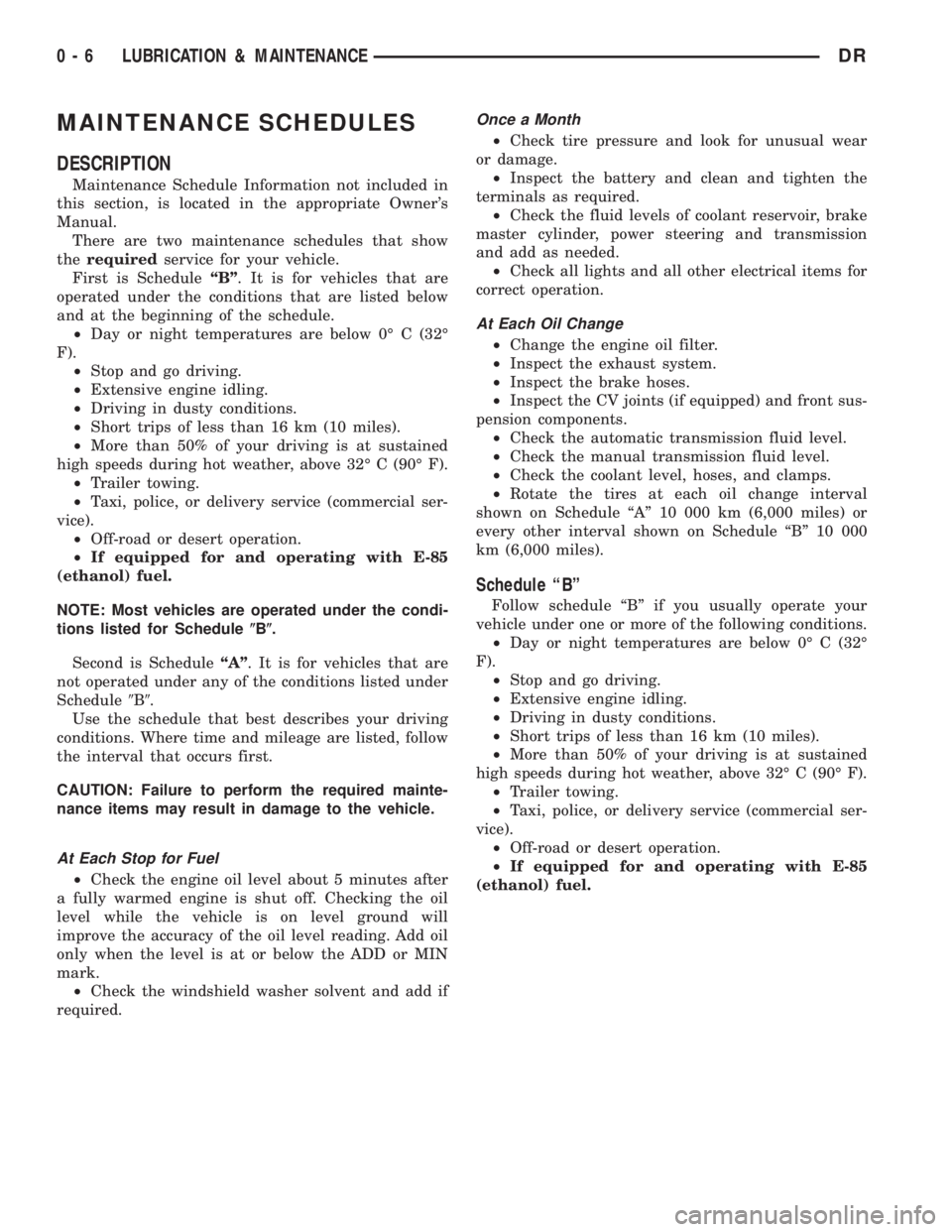
MAINTENANCE SCHEDULES
DESCRIPTION
Maintenance Schedule Information not included in
this section, is located in the appropriate Owner's
Manual.
There are two maintenance schedules that show
therequiredservice for your vehicle.
First is ScheduleªBº. It is for vehicles that are
operated under the conditions that are listed below
and at the beginning of the schedule.
²Day or night temperatures are below 0É C (32É
F).
²Stop and go driving.
²Extensive engine idling.
²Driving in dusty conditions.
²Short trips of less than 16 km (10 miles).
²More than 50% of your driving is at sustained
high speeds during hot weather, above 32É C (90É F).
²Trailer towing.
²Taxi, police, or delivery service (commercial ser-
vice).
²Off-road or desert operation.
²If equipped for and operating with E-85
(ethanol) fuel.
NOTE: Most vehicles are operated under the condi-
tions listed for Schedule(B(.
Second is ScheduleªAº. It is for vehicles that are
not operated under any of the conditions listed under
Schedule9B9.
Use the schedule that best describes your driving
conditions. Where time and mileage are listed, follow
the interval that occurs first.
CAUTION: Failure to perform the required mainte-
nance items may result in damage to the vehicle.
At Each Stop for Fuel
²Check the engine oil level about 5 minutes after
a fully warmed engine is shut off. Checking the oil
level while the vehicle is on level ground will
improve the accuracy of the oil level reading. Add oil
only when the level is at or below the ADD or MIN
mark.
²Check the windshield washer solvent and add if
required.
Once a Month
²Check tire pressure and look for unusual wear
or damage.
²Inspect the battery and clean and tighten the
terminals as required.
²Check the fluid levels of coolant reservoir, brake
master cylinder, power steering and transmission
and add as needed.
²Check all lights and all other electrical items for
correct operation.
At Each Oil Change
²Change the engine oil filter.
²Inspect the exhaust system.
²Inspect the brake hoses.
²Inspect the CV joints (if equipped) and front sus-
pension components.
²Check the automatic transmission fluid level.
²Check the manual transmission fluid level.
²Check the coolant level, hoses, and clamps.
²Rotate the tires at each oil change interval
shown on Schedule ªAº 10 000 km (6,000 miles) or
every other interval shown on Schedule ªBº 10 000
km (6,000 miles).
Schedule ªBº
Follow schedule ªBº if you usually operate your
vehicle under one or more of the following conditions.
²Day or night temperatures are below 0É C (32É
F).
²Stop and go driving.
²Extensive engine idling.
²Driving in dusty conditions.
²Short trips of less than 16 km (10 miles).
²More than 50% of your driving is at sustained
high speeds during hot weather, above 32É C (90É F).
²Trailer towing.
²Taxi, police, or delivery service (commercial ser-
vice).
²Off-road or desert operation.
²If equipped for and operating with E-85
(ethanol) fuel.
0 - 6 LUBRICATION & MAINTENANCEDR
Page 23 of 2895
Miles 105,000 108,000 111,000 114,000 117,000 120,000
(Kilometers) (168 000) (173 000) (178 000) (182 000) (187 000) (192 000)
Change engine oil and engine
oil filter.XXXXX X
Lubricate outer tie rod ends
2500/3500 (4X4) models only.XXX
Drain and refill transfer case
fluid.X
Change rear axle fluid. X X
Change front axle fluid (4X4). X X
Inspect brake linings. X X
Inspect engine air cleaner
filter, replace if necessary.XX
Replace spark plugs.X
Replace ignition cables
(5.7L/5.9L/8.0L).X
Inspect PCV valve, replace
as necessary.X*
Inspect auto tension drive belt
and replace if required
(3.7L/4.7L/5.7L/5.9L/8.0L).X³ X³
Drain and refill automatic
tranmission fluid, change filter
and adjust bands (46RE/
47RE/48RE).X
Drain and refill automatic
tranmission fluid and change
main sump filter (45RFE/
545RFE only).X
* This maintenance is recommended by the manu-
facture to the owner but is not required to maintain
the emissions warranty.
³ This maintenance is not required if previously
replaced.
Inspection and service should also be performed
anytime a malfunction is observed or suspected.
Retain all receipts.
0 - 10 LUBRICATION & MAINTENANCEDR
MAINTENANCE SCHEDULES (Continued)
Page 25 of 2895
![DODGE RAM 2003 Service Repair Manual Miles 72,000 78,000 84,000 90,000 96,000 100,000
(Kilometers) (115 000) (125 000) (134 000) (144 000) (154 000) (160 000)
[Months] [72] [78] [84] [90] [96]
Change engine oil and engine oil filter.XXXX DODGE RAM 2003 Service Repair Manual Miles 72,000 78,000 84,000 90,000 96,000 100,000
(Kilometers) (115 000) (125 000) (134 000) (144 000) (154 000) (160 000)
[Months] [72] [78] [84] [90] [96]
Change engine oil and engine oil filter.XXXX](/img/12/56913/w960_56913-24.png)
Miles 72,000 78,000 84,000 90,000 96,000 100,000
(Kilometers) (115 000) (125 000) (134 000) (144 000) (154 000) (160 000)
[Months] [72] [78] [84] [90] [96]
Change engine oil and engine oil filter.XXXXX
Lubricate outer tie rod ends 2500/3500
(4X4) models only.XXXXX
Drain and refill transfer case fluid. X
Flush and replace engine coolant, if not
done at 60 mos.X
Flush and replace Power Steering Fluid.X
Inspect brake linings. X X
Replace engine air cleaner filter.X
Replace spark plugs.X
Replace ignition cables (5.7L/5.9L/
8.0L).X
Inspect PCV valve, replace as
necessary.X*
Inspect auto tension drive belt and
replace if required (3.7L/4.7L/5.7L/5.9L/
8.0L).X
Drain and refill automatic tranmission
fluid, change filter and adjust bands
(46RE/47RE/48RE).X
Drain and refill automatic tranmission
fluid and change main sump filter and
spin-on cooler return filter (if equipped)
[45RFE/545RFE only].X
Miles 102,000 108,000 114,000 120,000
(Kilometers) (163 000) (173 000) (182 000) (192 000)
[Months] [102] [108] [114] [120]
Change engine oil and engine oil filter. X X X X
Check transfer case fluid level.X
Lubricate outer tie rod ends 2500/3500 (4X4) models only. X X X X
Inspect brake linings. X
Inspect auto tension drive belt and replace if required
(3.7L/4.7L/5.7L/5.9L/8.0L).X³X³
Replace engine air cleaner filter.X
Replace spark plugs.X
* This maintenance is recommended by the manu-
facture to the owner but is not required to maintain
the emissions warranty.
³ This maintenance is not required if previously
replaced.
Inspection and service should also be performed
anytime a malfunction is observed or suspected.
Retain all receipts.WARNING: You can be badly injured working on or
around a motor vehicle. Do only that service work
for which you have the knowledge and the right
equipment. If you have any doubt about your ability
to perform a service job, take your vehicle to a
competent mechanic.
0 - 12 LUBRICATION & MAINTENANCEDR
MAINTENANCE SCHEDULES (Continued)
Page 407 of 2895
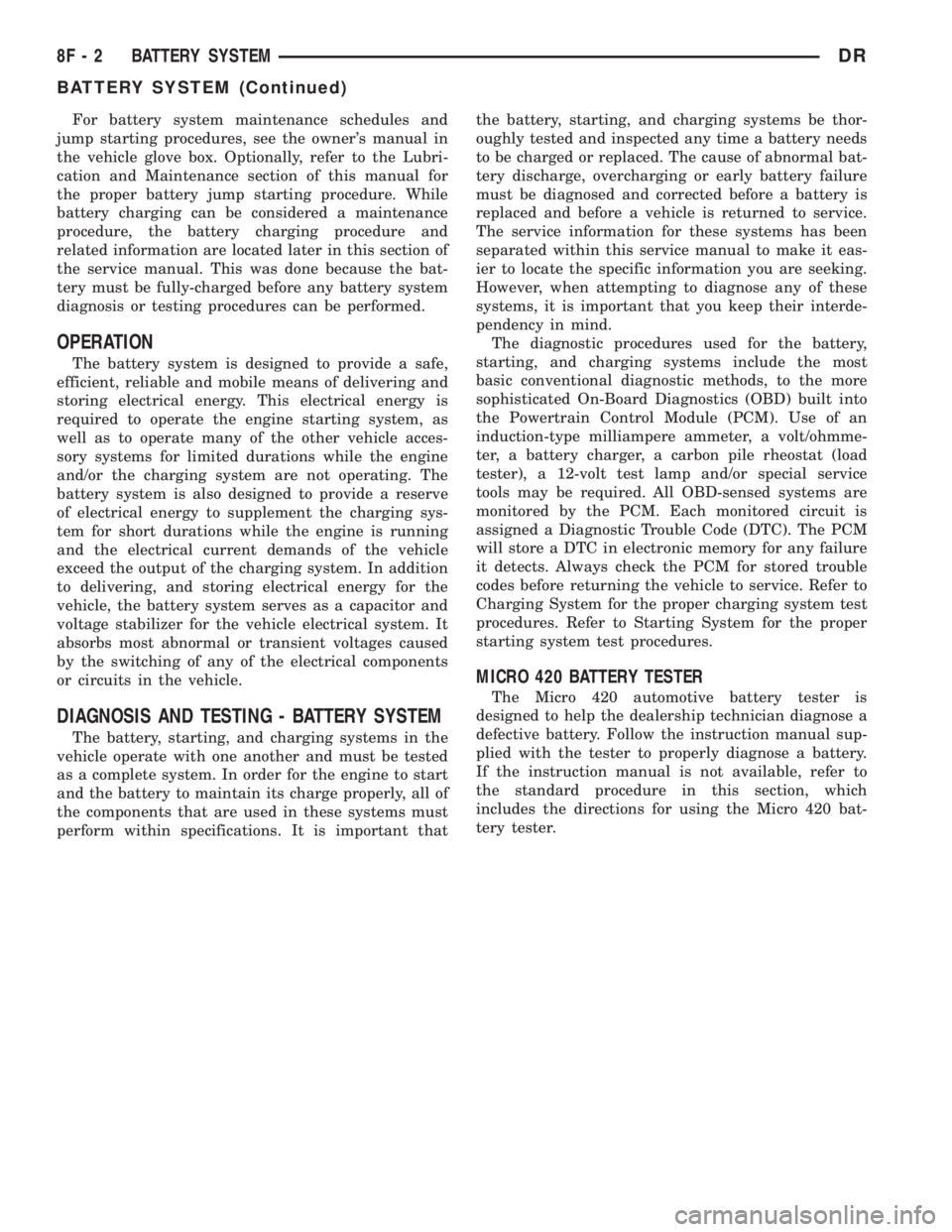
For battery system maintenance schedules and
jump starting procedures, see the owner's manual in
the vehicle glove box. Optionally, refer to the Lubri-
cation and Maintenance section of this manual for
the proper battery jump starting procedure. While
battery charging can be considered a maintenance
procedure, the battery charging procedure and
related information are located later in this section of
the service manual. This was done because the bat-
tery must be fully-charged before any battery system
diagnosis or testing procedures can be performed.
OPERATION
The battery system is designed to provide a safe,
efficient, reliable and mobile means of delivering and
storing electrical energy. This electrical energy is
required to operate the engine starting system, as
well as to operate many of the other vehicle acces-
sory systems for limited durations while the engine
and/or the charging system are not operating. The
battery system is also designed to provide a reserve
of electrical energy to supplement the charging sys-
tem for short durations while the engine is running
and the electrical current demands of the vehicle
exceed the output of the charging system. In addition
to delivering, and storing electrical energy for the
vehicle, the battery system serves as a capacitor and
voltage stabilizer for the vehicle electrical system. It
absorbs most abnormal or transient voltages caused
by the switching of any of the electrical components
or circuits in the vehicle.
DIAGNOSIS AND TESTING - BATTERY SYSTEM
The battery, starting, and charging systems in the
vehicle operate with one another and must be tested
as a complete system. In order for the engine to start
and the battery to maintain its charge properly, all of
the components that are used in these systems must
perform within specifications. It is important thatthe battery, starting, and charging systems be thor-
oughly tested and inspected any time a battery needs
to be charged or replaced. The cause of abnormal bat-
tery discharge, overcharging or early battery failure
must be diagnosed and corrected before a battery is
replaced and before a vehicle is returned to service.
The service information for these systems has been
separated within this service manual to make it eas-
ier to locate the specific information you are seeking.
However, when attempting to diagnose any of these
systems, it is important that you keep their interde-
pendency in mind.
The diagnostic procedures used for the battery,
starting, and charging systems include the most
basic conventional diagnostic methods, to the more
sophisticated On-Board Diagnostics (OBD) built into
the Powertrain Control Module (PCM). Use of an
induction-type milliampere ammeter, a volt/ohmme-
ter, a battery charger, a carbon pile rheostat (load
tester), a 12-volt test lamp and/or special service
tools may be required. All OBD-sensed systems are
monitored by the PCM. Each monitored circuit is
assigned a Diagnostic Trouble Code (DTC). The PCM
will store a DTC in electronic memory for any failure
it detects. Always check the PCM for stored trouble
codes before returning the vehicle to service. Refer to
Charging System for the proper charging system test
procedures. Refer to Starting System for the proper
starting system test procedures.
MICRO 420 BATTERY TESTER
The Micro 420 automotive battery tester is
designed to help the dealership technician diagnose a
defective battery. Follow the instruction manual sup-
plied with the tester to properly diagnose a battery.
If the instruction manual is not available, refer to
the standard procedure in this section, which
includes the directions for using the Micro 420 bat-
tery tester.
8F - 2 BATTERY SYSTEMDR
BATTERY SYSTEM (Continued)
Page 410 of 2895
ponents. In addition to the maintenance schedules
found in this service manual and the owner's man-
ual, it is recommended that these procedures be per-
formed any time the battery or related components
must be removed for vehicle service.
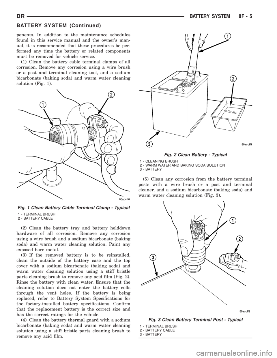
(1) Clean the battery cable terminal clamps of all
corrosion. Remove any corrosion using a wire brush
or a post and terminal cleaning tool, and a sodium
bicarbonate (baking soda) and warm water cleaning
solution (Fig. 1).
(2) Clean the battery tray and battery holddown
hardware of all corrosion. Remove any corrosion
using a wire brush and a sodium bicarbonate (baking
soda) and warm water cleaning solution. Paint any
exposed bare metal.
(3) If the removed battery is to be reinstalled,
clean the outside of the battery case and the top
cover with a sodium bicarbonate (baking soda) and
warm water cleaning solution using a stiff bristle
parts cleaning brush to remove any acid film (Fig. 2).
Rinse the battery with clean water. Ensure that the
cleaning solution does not enter the battery cells
through the vent holes. If the battery is being
replaced, refer to Battery System Specifications for
the factory-installed battery specifications. Confirm
that the replacement battery is the correct size and
has the correct ratings for the vehicle.
(4) Clean the battery thermal guard with a sodium
bicarbonate (baking soda) and warm water cleaning
solution using a stiff bristle parts cleaning brush to
remove any acid film.(5) Clean any corrosion from the battery terminal
posts with a wire brush or a post and terminal
cleaner, and a sodium bicarbonate (baking soda) and
warm water cleaning solution (Fig. 3).
Fig. 1 Clean Battery Cable Terminal Clamp - Typical
1 - TERMINAL BRUSH
2 - BATTERY CABLE
Fig. 2 Clean Battery - Typical
1 - CLEANING BRUSH
2 - WARM WATER AND BAKING SODA SOLUTION
3 - BATTERY
Fig. 3 Clean Battery Terminal Post - Typical
1 - TERMINAL BRUSH
2 - BATTERY CABLE
3 - BATTERY
DRBATTERY SYSTEM 8F - 5
BATTERY SYSTEM (Continued)
Page 1465 of 2895
ENGINE OIL SPECIFICATION
CAUTION: Do not use non-detergent or straight
mineral oil when adding or changing crankcase
lubricant. Engine failure can result.
API SERVICE GRADE CERTIFIED
Use an engine oil that is API Service Grade Certi-
fied. MOPARtprovides engine oils that conform to
this service grade.
SAE VISCOSITY
An SAE viscosity grade is used to specify the vis-
cosity of engine oil. Use only engine oils with multi-
ple viscosities such as 5W-30 in the 5.7L engines.
These are specified with a dual SAE viscosity grade
which indicates the cold-to-hot temperature viscosity
range. Select an engine oil that is best suited to your
particular temperature range and variation.
ENERGY CONSERVING OIL
An Energy Conserving type oil is recommended for
gasoline engines. The designation of ENERGY CON-
SERVING is located on the label of an engine oil con-
tainer.
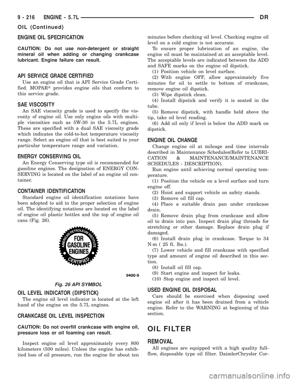
CONTAINER IDENTIFICATION
Standard engine oil identification notations have
been adopted to aid in the proper selection of engine
oil. The identifying notations are located on the label
of engine oil plastic bottles and the top of engine oil
cans (Fig. 26).
OIL LEVEL INDICATOR (DIPSTICK)
The engine oil level indicator is located at the left
hand of the engine on the 5.7L engines.
CRANKCASE OIL LEVEL INSPECTION
CAUTION: Do not overfill crankcase with engine oil,
pressure loss or oil foaming can result.
Inspect engine oil level approximately every 800
kilometers (500 miles). Unless the engine has exhib-
ited loss of oil pressure, run the engine for about tenminutes before checking oil level. Checking engine oil
level on a cold engine is not accurate.
To ensure proper lubrication of an engine, the
engine oil must be maintained at an acceptable level.
The acceptable levels are indicated between the ADD
and SAFE marks on the engine oil dipstick.
(1) Position vehicle on level surface.
(2) With engine OFF, allow approximately five
minutes for oil to settle to bottom of crankcase,
remove engine oil dipstick.
(3) Wipe dipstick clean.
(4) Install dipstick and verify it is seated in the
tube.
(5) Remove dipstick, with handle held above the
tip, take oil level reading.
(6) Add oil only if level is below the ADD mark on
dipstick.
ENGINE OIL CHANGE
Change engine oil at mileage and time intervals
described in Maintenance Schedules(Refer to LUBRI-
CATION & MAINTENANCE/MAINTENANCE
SCHEDULES - DESCRIPTION).
Run engine until achieving normal operating tem-
perature.
(1) Position the vehicle on a level surface and turn
engine off.
(2) Hoist and support vehicle on safety stands.
(3) Remove oil fill cap.
(4) Place a suitable drain pan under crankcase
drain.
(5) Remove drain plug from crankcase and allow
oil to drain into pan. Inspect drain plug threads for
stretching or other damage. Replace drain plug if
damaged.
(6) Install drain plug in crankcase. Torque to 34
N´m ( 25 ft. lbs.).
(7) Lower vehicle and fill crankcase with specified
type and amount of engine oil described in this sec-
tion.
(8) Install oil fill cap.
(9) Start engine and inspect for leaks.
(10) Stop engine and inspect oil level.
USED ENGINE OIL DISPOSAL
Care should be exercised when disposing used
engine oil after it has been drained from a vehicle
engine. Refer to the WARNING at beginning of this
section.
OIL FILTER
REMOVAL
All engines are equipped with a high quality full-
flow, disposable type oil filter. DaimlerChrysler Cor-
Fig. 26 API SYMBOL
9 - 216 ENGINE - 5.7LDR
OIL (Continued)
Page 2561 of 2895
METHOD 2 (RELOCATE TIRE ON WHEEL)
NOTE: Rotating the tire on wheel is particularly
effective when there is runout in both tire and
wheel.
(1) Remove tire from wheel and mount wheel on
service dynamic balance machine.
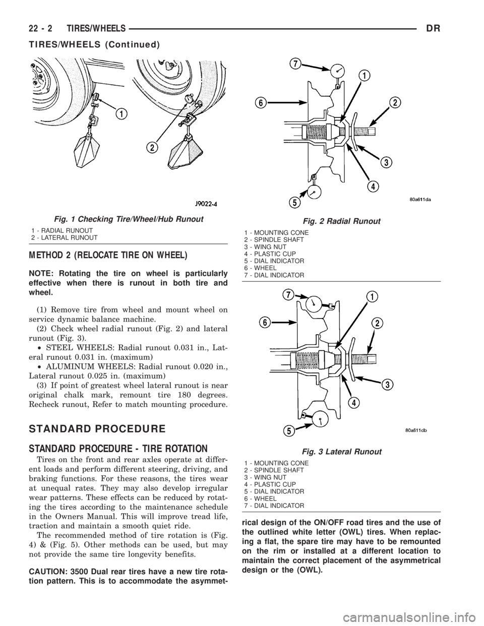
(2) Check wheel radial runout (Fig. 2) and lateral
runout (Fig. 3).
²STEEL WHEELS: Radial runout 0.031 in., Lat-
eral runout 0.031 in. (maximum)
²ALUMINUM WHEELS: Radial runout 0.020 in.,
Lateral runout 0.025 in. (maximum)
(3) If point of greatest wheel lateral runout is near
original chalk mark, remount tire 180 degrees.
Recheck runout, Refer to match mounting procedure.
STANDARD PROCEDURE
STANDARD PROCEDURE - TIRE ROTATION
Tires on the front and rear axles operate at differ-
ent loads and perform different steering, driving, and
braking functions. For these reasons, the tires wear
at unequal rates. They may also develop irregular
wear patterns. These effects can be reduced by rotat-
ing the tires according to the maintenance schedule
in the Owners Manual. This will improve tread life,
traction and maintain a smooth quiet ride.
The recommended method of tire rotation is (Fig.
4) & (Fig. 5). Other methods can be used, but may
not provide the same tire longevity benefits.
CAUTION: 3500 Dual rear tires have a new tire rota-
tion pattern. This is to accommodate the asymmet-rical design of the ON/OFF road tires and the use of
the outlined white letter (OWL) tires. When replac-
ing a flat, the spare tire may have to be remounted
on the rim or installed at a different location to
maintain the correct placement of the asymmetrical
design or the (OWL).
Fig. 1 Checking Tire/Wheel/Hub Runout
1 - RADIAL RUNOUT
2 - LATERAL RUNOUT
Fig. 2 Radial Runout
1 - MOUNTING CONE
2 - SPINDLE SHAFT
3 - WING NUT
4 - PLASTIC CUP
5 - DIAL INDICATOR
6 - WHEEL
7 - DIAL INDICATOR
Fig. 3 Lateral Runout
1 - MOUNTING CONE
2 - SPINDLE SHAFT
3 - WING NUT
4 - PLASTIC CUP
5 - DIAL INDICATOR
6 - WHEEL
7 - DIAL INDICATOR
22 - 2 TIRES/WHEELSDR
TIRES/WHEELS (Continued)