turn signal testing DODGE RAM 2003 Service Repair Manual
[x] Cancel search | Manufacturer: DODGE, Model Year: 2003, Model line: RAM, Model: DODGE RAM 2003Pages: 2895, PDF Size: 83.15 MB
Page 270 of 2895
INSTALLATION
(1) Connect the harness to the sensor.Be sure
the seal is securely in place between the sensor
and the wiring connector.
(2) Install the O-ring on the sensor (if removed).
(3) Insert the sensor in the differential housing.
(4) Install the sensor shield.
(5) Install the sensor mounting stud and tighten to
24 N´m (200 in. lbs.).
(6) Install the brake line on the sensor stud and
install the nut.
(7) Lower the vehicle.
TONE WHEEL
DIAGNOSIS AND TESTING - REAR WHEEL
SPEED SENSOR
Diagnosis of base brake conditions which are
mechanical in nature should be performed first. This
includes brake noise, lack of power assist, parking
brake, or vehicle vibration during normal braking.
The Antilock brake system performs several self-
tests every time the ignition switch is turned on and
the vehicle is driven. The CAB monitors the system
inputs and outputs circuits to verify the system is
operating properly. If the CAB senses a malfunction
in the system it will set a DTC into memory and trig-
ger the warning lamp.
NOTE: The MDS or DRB III scan tool is used to
diagnose the Antilock Brake system. For test proce-
dures refer to the Chassis Diagnostic Manual.
HYDRAULIC/MECHANICAL
DESCRIPTION - ELECTRONIC VARIABLE
BRAKE PROPORTIONING
Vehicles equipped with ABS use electronic variable
brake proportioning (EVBP) to balance front-to-rear
braking. The EVBP is used in place of a rear propor-
tioning valve. The EVBP system uses the ABS sys-
tem to control the slip of the rear wheels in partial
braking range. The braking force of the rear wheels
is controlled electronically by using the inlet and out-
let valves located in the integrated control unit
(ICU).
OPERATION - ELECTRONIC VARIABLE BRAKE
PROPORTIONING
EVBP is able to decrease, hold and increase rear
brake pressure without activating full ABS control.
Upon entry into EVBP the inlet valve for the rear
brake circuit is switched on so that the fluid supplyfrom the master cylinder is shut off. In order to
decrease the rear brake pressure, the outlet valve for
the rear brake circuit is pulsed. This allows fluid to
enter the low pressure accumulator (LPA) in the
hydraulic control unit (HCU) resulting in a drop in
fluid pressure to the rear brakes. In order to increase
the rear brake pressure, the outlet valve is switched
off and the inlet valve is pulsed. This increases the
pressure to the rear brakes.
The EVBP will remain functional during many
ABS fault modes. If both the red BRAKE and amber
ABS warning indicators are illuminated, the EVBP
may not be functioning.
HCU (HYDRAULIC CONTROL
UNIT)
DESCRIPTION
The HCU consists of a valve body, pump motor, low
pressure accumulators, inlet valves, outlet valves and
noise attenuators.
OPERATION
Accumulators in the valve body store extra fluid
released to the system for ABS mode operation. The
pump provides the fluid volume needed and is oper-
ated by a DC type motor. The motor is controlled by
the CAB.
The valves modulate brake pressure during
antilock braking and are controlled by the CAB.
The HCU provides three channel pressure control
to the front and rear brakes. One channel controls
the rear wheel brakes in tandem. The two remaining
channels control the front wheel brakes individually.
During antilock braking, the solenoid valves are
opened and closed as needed.
During normal braking, the HCU solenoid valves
and pump are not activated. The master cylinder and
power booster operate the same as a vehicle without
an ABS brake system.
NOTE: The three modes mentioned below do occur
but not necessarily in the order listed everytime.
During antilock braking, solenoid valve pressure
modulation occurs in three stages, pressure increase,
pressure hold, and pressure decrease. The valves are
all contained in the valve body portion of the HCU.
PRESSURE DECREASE
The outlet valve is opened and the inlet valve is
closed during the pressure decrease cycle.
A pressure decrease cycle is initiated when speed
sensor signals indicate high wheel slip at one or
more wheels. At this point, the CAB closes the inlet
DRBRAKES - ABS 5 - 43
REAR WHEEL SPEED SENSOR (Continued)
Page 366 of 2895
CONDITION POSSIBLE CAUSES CORRECTION
CLOCK WILL NOT KEEP
SET TIME1. Fuse faulty. 1. Check Ignition-Off Draw (IOD) fuse in the
Integrated Power Module (IPM). Replace fuse, if
required.
2. Radio connector faulty. 2. Check for loose or corroded radio connector.
Repair, if required.
3. Wiring faulty. 3. Check for battery voltage at radio connector.
Repair wiring, if required.
4. Radio ground faulty. 4. Check for continuity between radio chassis and
a known good ground. There should be
continuity. Repair ground, if required.
5. Radio faulty. 5. Refer to appropriate Diagnostic Service
Manual.
POOR RADIO RECEPTION 1. Antenna faulty. 1. (Refer to 8 - ELECTRICAL/AUDIO/ANTENNA
BODY & CABLE - DIAGNOSIS AND TESTING).
2. Radio ground faulty. 2. Check for continuity between radio chassis and
a known good ground. There should be
continuity. Repair ground, if required.
3. Radio noise suppression
faulty.3. Repair or replace ground strap as necessary.
4. Radio faulty. 4. Refer to appropriate Diagnostic Service
Manual.
NO/POOR TAPE
OPERATION1. Faulty tape. 1. Insert known good tape and test operation.
2. Foreign objects behind
tape door.2. Remove foreign objects and test operation.
3. Dirty cassette tape head. 3. Clean head with Mopar Cassette Head
Cleaner.
4. Faulty tape deck. 4. Exchange or replace radio, if required.
NO COMPACT DISC
OPERATION1. Faulty CD. 1. Insert known good CD and test operation.
2. Foreign material on CD. 2. Clean CD and test operation.
3. Condensation on CD or
optics.3. Allow temperature of vehicle interior to stabilize
and test operation.
4. Faulty CD player. 4. Refer to appropriate Diagnostic Service
Manual.
AMPLIFIER
DESCRIPTION
The optional Infinity premium speaker system
includes a separate Infinity audio power amplifier.
The amplifier is a six channel unit and is rated at
240 total output watts. The amplifier is located
behind the glove box.
OPERATION
The power amplifier electronically increases the
frequency response of the normal audio signal output
from the radio amplifier in order to improve the
acoustic performance of the speakers. On vehiclesequipped with an amplifier, the amplifier section of
the radio becomes a pre-amplifier.
The amplifier receives audio signal inputs for
speaker channels from the radio, then sends ampli-
fied audio outputs through six separate channels
with dedicated feed and return circuits to the indi-
vidual speakers.
REMOVAL
(1) Disconnect and isolate the battery negative
cable.
(2) Remove glove box (Refer to 23 - BODY/IN-
STRUMENT PANEL/GLOVE BOX - REMOVAL).
DRAUDIO 8A - 3
AUDIO (Continued)
Page 380 of 2895
CHIME/BUZZER
TABLE OF CONTENTS
page page
CHIME/BUZZER
DESCRIPTION..........................1
OPERATION............................1DIAGNOSIS AND TESTING - CHIME
CONDITIONS..........................2
CHIME/BUZZER
DESCRIPTION
The chime module is located within the instrument
cluster and is not serviceable. The chime system pro-
vides the driver with warning chimes for:
²Air Bag
²Seat Belt
²Low Fuel
²Door Ajar
²Low Wash
²Park Brake
²Over Speed
²Turn Signal On
²Key-In Ignition
²Exterior Lamps ON
²Warning Lamp Announcement
²Transmission Over Temperature
OPERATION
FASTEN SEAT BELT
The seat belt reminder system uses both visual
and audible signals. The Instrument Cluster moni-
tors the driver seat belt buckle switch. When the
ignition switch transitions from OFF to RUN and the
driver seat belt has not been buckled, the Instrument
Cluster will illuminate the seat belt indicator lamp
and sound the chime. The system will always illumi-
nate the seat belt reminder lamp for four to eight
seconds when the ignition switch is turned to the ON
position. The CHIME will sound during the same
time interval if the driver's seat belt is not fastened.
The warning lamp will remain illuminated as long as
the seat belt remains unbuckled, and the ignition
switch is in the RUN position. Passenger seat belts
are not connected to the system.
HEADLAMPS REMINDER
The Instrument Cluster monitors the multiplex
headlamp switch. The headlamp audible warning will
alert the driver that the exterior lamps have been
left on. If the ignition switch is left off, the driver's
door open, and the headlamp switch is in the parklamp or headlamp position, the chime will sound
until the headlamp switch is turned off, the door is
closed or the battery protection time out expires.
KEY IN IGNITION REMINDER
The Instrument Cluster monitors the ignition
switch. The chime will activate if the drivers door is
opened and the key is in the ignition switch, with the
ignition switch in either the OFF, LOCK, or the
accessory (ACC) position. The chime will continue
until the key is removed from the ignition switch or
the door is closed.
DOOR AJAR CHIME
The Instrument Cluster monitors the door ajar
switches. A chime will sound once when the door is
opened, the ignition is in RUN position and vehicle
speed is present.
TURN SIGNAL ON
The Instrument Cluster monitors the multiplex
multifunction switch. The instrument cluster shall
remind the driver that either turn signal has been
left on by a continuous chime after the turn signal
indicator is left ON for 1.0 miles and the vehicle
speed is 15 mph or greater.
LOW FUEL REMINDER
When the fuel level drops to approximately 1/8
tank, the fuel symbol will light and a single chime
will sound. The light will remain on until fuel is
added.
OVER SPEED
During any ignition ON, the Instrument Cluster
maintains the most recently received speed. If the
vehicle speed exceeds a preprogramed limit set in the
instrument cluster it will activate a single chime.
WARNING LAMP ANNOUNCEMENT
The Instrument Cluster monitors critical engine
and transmission system parameters. If any of the
systems are out of their operating parameters, the
instrument cluster will illuminate a lamp and acti-
vate and audible chime.
DRCHIME/BUZZER 8B - 1
Page 452 of 2895
(2) Connect the new heating element electrical
connectors (Fig. 2).
(3) Connect the battery negative cable.
(4) Verify heated seat system operation.
(5) Install the appropriate seat cushion or seat
back trim cover. Make certain the seat wire harness
is correctly routed through the seat and seat back.
HEATED SEAT SENSOR
DESCRIPTION
The heated seat temperature sensor is a Negative
Temperature Coefficient (NTC) thermistor. One tem-
perature sensor is used for each seat. This tempera-
ture sensor is located in the seat cushion heating
element on all models.
The heated seat temperature sensor cannot be
repaired or adjusted and must be replaced if defec-
tive. The heated seat cushion element must be
replaced if the temperature sensor is defective. Refer
to the procedure in this section of the service man-
ual.
OPERATION
When the temperature of the seat cushion cover
rises, the resistance of the sensor decreases. The
heated seat module supplies five-volts to one side of
each sensor, and monitors the voltage drop through
the sensor on a return circuit. The heated seat mod-
ule uses this temperature sensor input to monitorthe temperature of the seat, and regulates the cur-
rent flow to the seat heating elements accordingly.
DIAGNOSIS AND TESTING - HEATED SEAT
SENSOR
NOTE: Any resistance values (OHMSV) given in the
following text are supplied using the automatic
range generated by a FLUKETautomotive meter. If
another type of measuring device is used, the val-
ues generated may not be the same as the results
shown here, or may have to be converted to the
range used here.
(1) Position the driver seat in the full rearward
position.
(2) Unclip the heated seat module from the bottom
of the drivers seat cushion pan.
(3) Back-probe the heated seat module wire har-
ness connector, do not disconnect. Check cavity (#7
for passenger, #8 for driver seat) for a range in volt-
age from approx. 1.72 ± 3.0 volts. It should be within
this range, If OK check the heated seat element. If
NOT OK, check for the proper 5 volt supply to the
heated seat sensor, from the module. Refer to Wiring
for specific information. If 5 volts is not being sup-
plied to the sensor from the module, replace the
heated seat module.
(4) Test the seat wire harness between the heated
seat module connector and the heated seat wire har-
ness connector for shorted or open circuits. If OK,
refer toDiagnosis and Testing the Heated Seat
Modulein Electronic Control Modules, for the
proper heated seat module diagnosis and testing pro-
cedures. If not OK, repair the shorted or open heated
seat wire harness as required.
REMOVAL
(1) For heated seat sensor replacement procedure
(Refer to 8 - ELECTRICAL/HEATED SEATS/
HEATED SEAT ELEMENT - REMOVAL).
HEATED SEAT SWITCH
DESCRIPTION
The momentary, bidirectional rocker-type heated
seat switch (Fig. 4) provides a resistor-multiplexed
signal to the heated seat module via a mux circuit.
Each switch has a center neutral position and
momentary Low and High positions so that both the
driver and the front seat passenger can select a pre-
ferred level of seat heating. Each heated seat switch
has two Light-Emitting Diode (LED) indicator lamps,
which indicate the selected mode (Low or High) of
the seat heater. These indicator lamps also provide
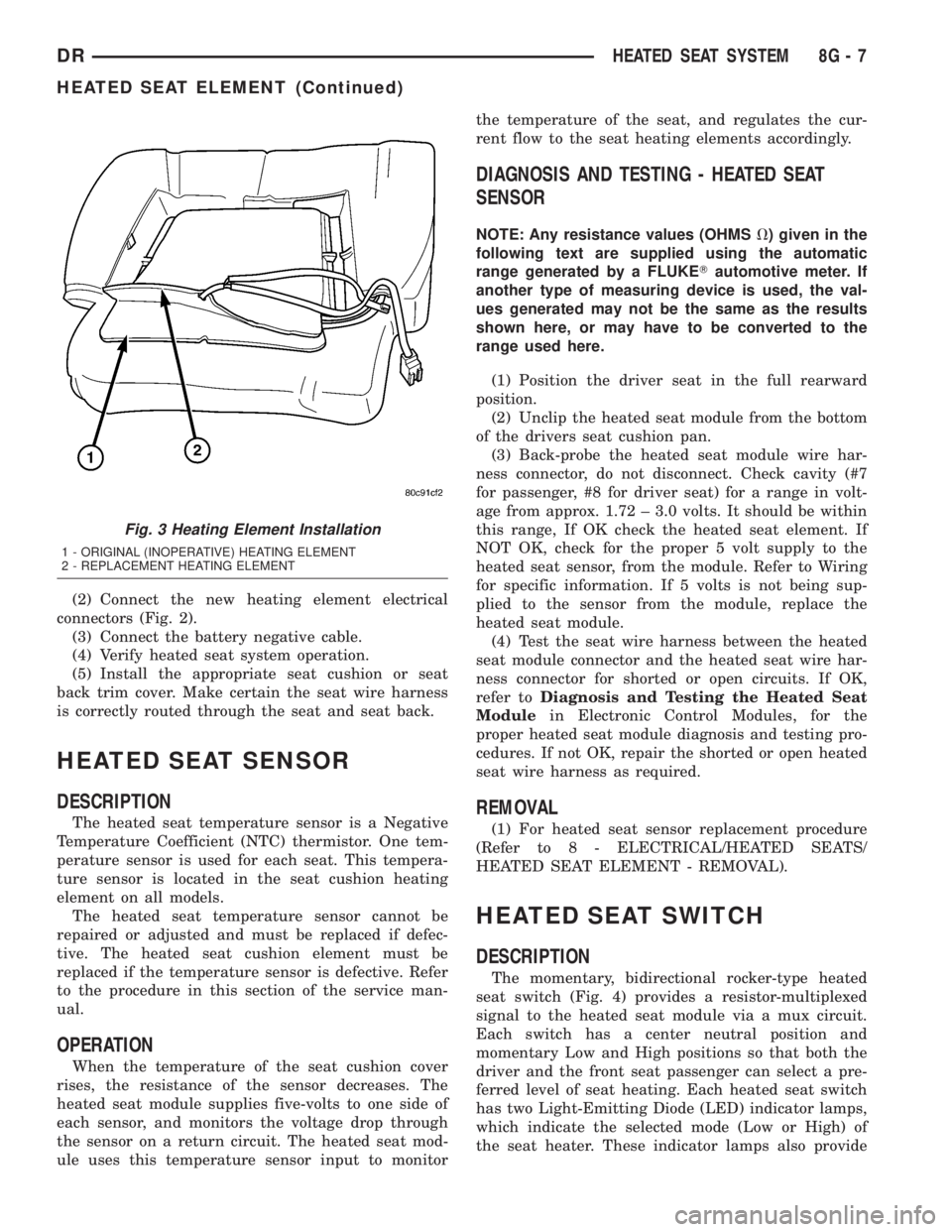
Fig. 3 Heating Element Installation
1 - ORIGINAL (INOPERATIVE) HEATING ELEMENT
2 - REPLACEMENT HEATING ELEMENT
DRHEATED SEAT SYSTEM 8G - 7
HEATED SEAT ELEMENT (Continued)
Page 453 of 2895
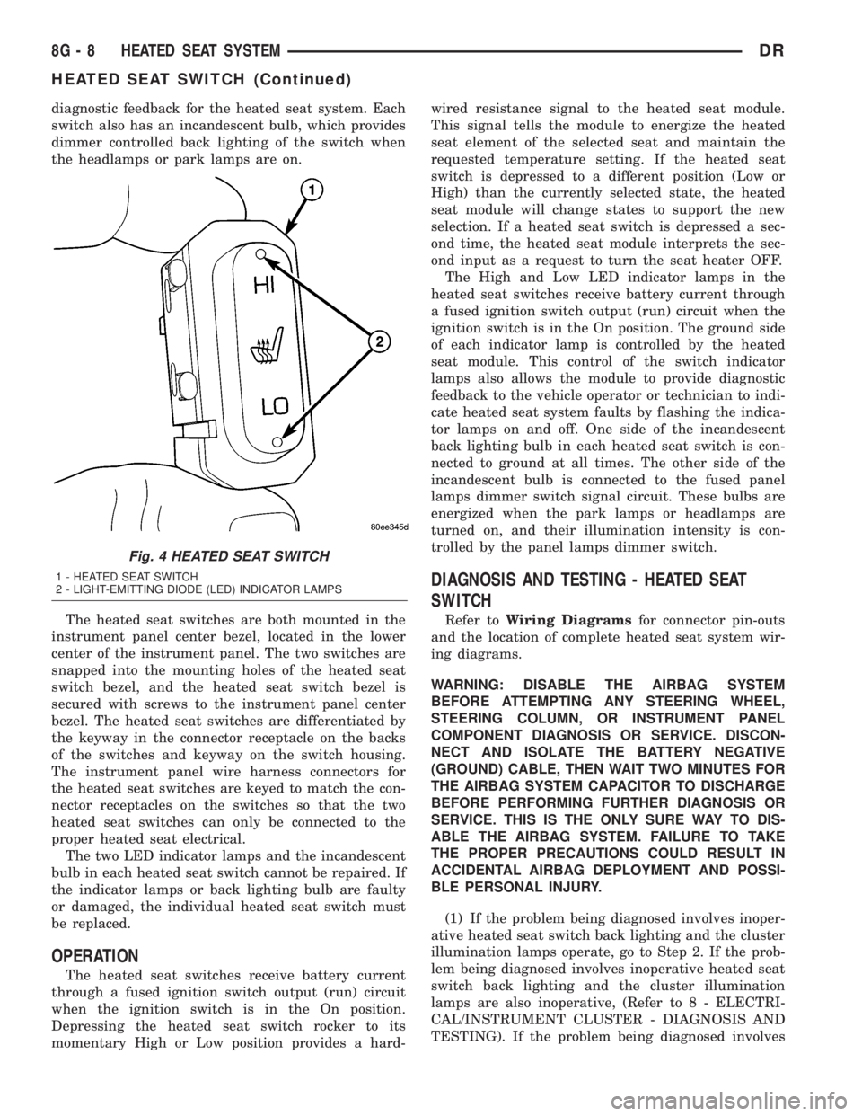
diagnostic feedback for the heated seat system. Each
switch also has an incandescent bulb, which provides
dimmer controlled back lighting of the switch when
the headlamps or park lamps are on.
The heated seat switches are both mounted in the
instrument panel center bezel, located in the lower
center of the instrument panel. The two switches are
snapped into the mounting holes of the heated seat
switch bezel, and the heated seat switch bezel is
secured with screws to the instrument panel center
bezel. The heated seat switches are differentiated by
the keyway in the connector receptacle on the backs
of the switches and keyway on the switch housing.
The instrument panel wire harness connectors for
the heated seat switches are keyed to match the con-
nector receptacles on the switches so that the two
heated seat switches can only be connected to the
proper heated seat electrical.
The two LED indicator lamps and the incandescent
bulb in each heated seat switch cannot be repaired. If
the indicator lamps or back lighting bulb are faulty
or damaged, the individual heated seat switch must
be replaced.
OPERATION
The heated seat switches receive battery current
through a fused ignition switch output (run) circuit
when the ignition switch is in the On position.
Depressing the heated seat switch rocker to its
momentary High or Low position provides a hard-wired resistance signal to the heated seat module.
This signal tells the module to energize the heated
seat element of the selected seat and maintain the
requested temperature setting. If the heated seat
switch is depressed to a different position (Low or
High) than the currently selected state, the heated
seat module will change states to support the new
selection. If a heated seat switch is depressed a sec-
ond time, the heated seat module interprets the sec-
ond input as a request to turn the seat heater OFF.
The High and Low LED indicator lamps in the
heated seat switches receive battery current through
a fused ignition switch output (run) circuit when the
ignition switch is in the On position. The ground side
of each indicator lamp is controlled by the heated
seat module. This control of the switch indicator
lamps also allows the module to provide diagnostic
feedback to the vehicle operator or technician to indi-
cate heated seat system faults by flashing the indica-
tor lamps on and off. One side of the incandescent
back lighting bulb in each heated seat switch is con-
nected to ground at all times. The other side of the
incandescent bulb is connected to the fused panel
lamps dimmer switch signal circuit. These bulbs are
energized when the park lamps or headlamps are
turned on, and their illumination intensity is con-
trolled by the panel lamps dimmer switch.
DIAGNOSIS AND TESTING - HEATED SEAT
SWITCH
Refer toWiring Diagramsfor connector pin-outs
and the location of complete heated seat system wir-
ing diagrams.
WARNING: DISABLE THE AIRBAG SYSTEM
BEFORE ATTEMPTING ANY STEERING WHEEL,
STEERING COLUMN, OR INSTRUMENT PANEL
COMPONENT DIAGNOSIS OR SERVICE. DISCON-
NECT AND ISOLATE THE BATTERY NEGATIVE
(GROUND) CABLE, THEN WAIT TWO MINUTES FOR
THE AIRBAG SYSTEM CAPACITOR TO DISCHARGE
BEFORE PERFORMING FURTHER DIAGNOSIS OR
SERVICE. THIS IS THE ONLY SURE WAY TO DIS-
ABLE THE AIRBAG SYSTEM. FAILURE TO TAKE
THE PROPER PRECAUTIONS COULD RESULT IN
ACCIDENTAL AIRBAG DEPLOYMENT AND POSSI-
BLE PERSONAL INJURY.
(1) If the problem being diagnosed involves inoper-
ative heated seat switch back lighting and the cluster
illumination lamps operate, go to Step 2. If the prob-
lem being diagnosed involves inoperative heated seat
switch back lighting and the cluster illumination
lamps are also inoperative, (Refer to 8 - ELECTRI-
CAL/INSTRUMENT CLUSTER - DIAGNOSIS AND
TESTING). If the problem being diagnosed involves
Fig. 4 HEATED SEAT SWITCH
1 - HEATED SEAT SWITCH
2 - LIGHT-EMITTING DIODE (LED) INDICATOR LAMPS
8G - 8 HEATED SEAT SYSTEMDR
HEATED SEAT SWITCH (Continued)
Page 454 of 2895
inoperative heated seat switch indicator lamps and
the heated seat elements do not heat, proceed. If the
problem being diagnosed involves inoperative heated
seat switch indicator lamps and the heated seat ele-
ments do heat, go to Step 6. If the problem being
diagnosed involves a heated seat switch indicator
lamp that remains illuminated after the heated seat
has been turned Off, (Refer to 8 - ELECTRICAL/
ELECTRONIC CONTROL MODULES/MEMORY
HEATED SEAT/MIRROR MODULE - DIAGNOSIS
AND TESTING).
(2) Disconnect and isolate the battery negative
cable. Remove the heated seat switch and bezel unit
from the instrument panel. Disconnect the heated
seat switch to be tested. Check for continuity
between the ground circuit cavity of the heated seat
switch and a good ground. There should be continu-
ity. If OK, go to Step 3. If not OK, repair the open
ground circuit to ground as required.
(3) Reconnect the battery negative cable. Turn the
park lamps on with the headlamp switch. Rotate the
panel lamps dimmer thumb wheel on the headlamp
switch upward to just before the interior lamps
detent. Check for battery voltage at the fused panel
lamps dimmer circuit cavity of the heated seat
switch. If OK, go to Step 4. If not OK, repair the
open fused panel lamps dimmer switch signal circuit
to the fuse in the Integrated Power Module as
required.
(4) Turn the ignition switch to the On position.
Check for battery voltage at the fused ignition switch
output (run) circuit cavity of the heated seat switch.
If OK, go to Step 5. If not OK, repair the open fused
ignition switch output (run) circuit as required.
(5) Check the continuity and resistance values of
the heated seat switch in the Neutral, Low and High
positions as shown in the Heated Seat Switch Conti-
nuity chart. If OK, refer to Step 6. If not OK, replace
the faulty heated seat switch.
HEATED SEAT SWITCH CONTINUITY
Switch PositionContinuity
BetweenResistance
Neutral 4 & 6 2.2 Kilohms
Low 4 & 6 .415 Kilohms
High 4 & 6 33 Ohms(6) Replace the inoperative heated seat switch
with a known good unit and test the operation of the
switch indicator lamps. If OK, discard the faulty
heated seat switch. If not OK, (Refer to 8 - ELEC-
TRICAL/ELECTRONIC CONTROL MODULES/
MEMORY HEATED SEAT/MIRROR MODULE -
DIAGNOSIS AND TESTING).
REMOVAL
(1) Disconnect and isolate the negative battery
cable.
(2) Wait two minutes for the system reserve capac-
itor to discharge before beginning any airbag or
instrument panel service.
(3) Remove the center bezel from the instrument
panel (Refer to 23 - BODY/INSTRUMENT PANEL/
INSTRUMENT PANEL CENTER BEZEL - REMOV-
AL).
(4) Remove the screws that secure the heated seat
switch bezel to the instrument panel center bezel.
(5) Remove the heated seat switch bezel and both
switches from the instrument panel as a unit.
(6) From the back of the heated seat switch bezel,
gently pry the switch free and push the heated seat
switch out through the front of the bezel.
INSTALLATION
NOTE: When installing the heated seat switches, be
certain they are installed in the proper mounting
holes of the heated seat switch bezel. The heated
seat switches are differentiated by the keyway in
the connector receptacle on the backs of the
switches and keyway on the switch housing (Fig.
4).
(1) From the back of the heated seat switch bezel,
gently push the heated seat switch in through the
front of the bezel.
(2) Position the heated seat switch bezel to the
instrument panel center bezel and install the retain-
ing screws.
(3) Install the center bezel on the instrument
panel (Refer to 23 - BODY/INSTRUMENT PANEL/
INSTRUMENT PANEL CENTER BEZEL - INSTAL-
LATION).
(4) Connect the battery negative cable.
(5) Verify vehicle and system operation.
DRHEATED SEAT SYSTEM 8G - 9
HEATED SEAT SWITCH (Continued)
Page 494 of 2895
INSTRUMENT CLUSTER
TABLE OF CONTENTS
page page
INSTRUMENT CLUSTER
DESCRIPTION..........................2
OPERATION............................6
DIAGNOSIS AND TESTING - INSTRUMENT
CLUSTER...........................10
REMOVAL.............................14
DISASSEMBLY.........................14
ASSEMBLY............................15
INSTALLATION.........................16
ABS INDICATOR
DESCRIPTION.........................17
OPERATION...........................17
AIRBAG INDICATOR
DESCRIPTION.........................18
OPERATION...........................18
BRAKE/PARK BRAKE INDICATOR
DESCRIPTION.........................18
OPERATION...........................19
DIAGNOSIS AND TESTING - BRAKE
INDICATOR..........................19
CARGO LAMP INDICATOR
DESCRIPTION.........................20
OPERATION...........................20
CHECK GAUGES INDICATOR
DESCRIPTION.........................21
OPERATION...........................21
CRUISE INDICATOR
DESCRIPTION.........................22
OPERATION...........................22
DOOR AJAR INDICATOR
DESCRIPTION.........................23
OPERATION...........................23
ENGINE TEMPERATURE GAUGE
DESCRIPTION.........................23
OPERATION...........................23
ETC INDICATOR
DESCRIPTION.........................24
OPERATION...........................25
FUEL GAUGE
DESCRIPTION.........................25
OPERATION...........................26
GEAR SELECTOR INDICATOR
DESCRIPTION.........................26
OPERATION...........................27
HIGH BEAM INDICATOR
DESCRIPTION.........................27
OPERATION...........................28LAMP OUT INDICATOR
DESCRIPTION.........................28
OPERATION...........................28
LOW FUEL INDICATOR
DESCRIPTION.........................29
OPERATION...........................29
MALFUNCTION INDICATOR LAMP (MIL)
DESCRIPTION.........................30
OPERATION...........................30
ODOMETER
DESCRIPTION.........................31
OPERATION...........................31
OIL PRESSURE GAUGE
DESCRIPTION.........................32
OPERATION...........................32
OVERDRIVE OFF INDICATOR
DESCRIPTION.........................33
OPERATION...........................33
SEATBELT INDICATOR
DESCRIPTION.........................34
OPERATION...........................34
SECURITY INDICATOR
DESCRIPTION.........................34
OPERATION...........................35
SERVICE 4WD INDICATOR
DESCRIPTION.........................35
OPERATION...........................36
SPEEDOMETER
DESCRIPTION.........................36
OPERATION...........................36
TACHOMETER
DESCRIPTION.........................37
OPERATION...........................37
TRANS TEMP INDICATOR
DESCRIPTION.........................38
OPERATION...........................38
TURN SIGNAL INDICATOR
DESCRIPTION.........................39
OPERATION...........................39
UPSHIFT INDICATOR
DESCRIPTION.........................40
OPERATION...........................40
VOLTAGE GAUGE
DESCRIPTION.........................40
OPERATION...........................41
WAIT-TO-START INDICATOR
DESCRIPTION.........................42
OPERATION...........................42
DRINSTRUMENT CLUSTER 8J - 1
Page 502 of 2895
ajar indicator, high beam indicator, and turn signal
indicators operate based upon hard wired inputs to
the EMIC. The brake indicator is controlled by PCI
data bus messages from the Controller Antilock
Brake (CAB) as well as by hard wired park brake
switch inputs to the EMIC. The seatbelt indicator is
controlled by the EMIC programming, PCI data bus
messages from the Airbag Control Module (ACM),
and a hard wired seat belt switch input to the EMIC.
The Malfunction Indicator Lamp (MIL) is normally
controlled by PCI data bus messages from the Pow-
ertrain Control Module (PCM); however, if the EMIC
loses PCI data bus communication, the EMIC cir-
cuitry will automatically turn the MIL on until PCI
data bus communication is restored. The EMIC uses
PCI data bus messages from the Front Control Mod-
ule (FCM), the PCM, the diesel engine only Engine
Control Module (ECM), the ACM, the CAB, and the
Sentry Key Immobilizer Module (SKIM) to control all
of the remaining indicators.
The various EMIC indicators are controlled by dif-
ferent strategies; some receive fused ignition switch
output from the EMIC circuitry and have a switched
ground, while others are grounded through the EMIC
circuitry and have a switched battery feed. However,
all indicators are completely controlled by the EMIC
microprocessor based upon various hard wired and
electronic message inputs. All indicators are illumi-
nated at a fixed intensity, which is not affected by
the selected illumination intensity of the EMIC gen-
eral illumination lamps.
In addition, certain indicators in this instrument
cluster are automatically configured or self-config-
ured. This feature allows the configurable indicators
to be enabled by the EMIC circuitry for compatibility
with certain optional equipment. The EMIC defaults
for the ABS indicator and airbag indicator are
enabled, and these configuration settings must be
programmatically disabled in the EMIC using a
DRBIIItscan tool for vehicles that do not have this
equipment. The automatically configured or self-con-
figured indicators remain latent in each EMIC at all
times and will be active only when the EMIC
receives the appropriate PCI message inputs for that
optional system or equipment.
The hard wired indicator inputs may be diagnosed
using conventional diagnostic methods. However, the
EMIC circuitry and PCI bus message controlled indi-
cators are diagnosed using the EMIC self-diagnostic
actuator test. (Refer to 8 - ELECTRICAL/INSTRU-
MENT CLUSTER - DIAGNOSIS AND TESTING).
Proper testing of the PCI data bus and the electronic
message inputs to the EMIC that control an indicator
requires the use of a DRBIIItscan tool. Refer to the
appropriate diagnostic information. Specific details ofthe operation for each indicator may be found else-
where in this service information.
CLUSTER ILLUMINATION
The EMIC has several illumination lamps that are
illuminated when the exterior lighting is turned on
with the headlamp switch. The illumination intensity
of these lamps is adjusted when the interior lighting
thumbwheel on the headlamp switch is rotated (down
to dim, up to brighten) to one of six available minor
detent positions. The EMIC monitors a resistor mul-
tiplexed input from the headlamp switch on a dim-
mer input circuit. In response to that input, the
EMIC electronic circuitry converts a 12-volt input it
receives from a fuse in the Integrated Power Module
(IPM) on a hard wired panel lamps dimmer switch
signal circuit into a 12-volt Pulse Width Modulated
(PWM) output. The EMIC uses this PWM output to
power the cluster illumination lamps and the VFD
units on the EMIC circuit board, then provides a syn-
chronized PWM output on the various hard wired
fused panel lamps dimmer switch signal circuits to
control and synchronize the illumination intensity of
other incandescent illumination lamps in the vehicle.
The cluster illumination lamps are grounded at all
times.
The EMIC also sends electronic dimming level
messages over the PCI data bus to other electronic
modules in the vehicle to control and synchronize the
illumination intensity of their VFD units to that of
the EMIC VFD units. In addition, the thumbwheel
on the headlamp switch has a Parade Mode position
to provide a parade mode. The EMIC monitors the
request for this mode from the headlamp switch,
then sends an electronic dimming level message over
the PCI data bus to illuminate all VFD units in the
vehicle at full (daytime) intensity for easier visibility
when driving in daylight with the exterior lighting
turned on.
The hard wired headlamp switch and EMIC panel
lamps dimmer inputs and outputs may be diagnosed
using conventional diagnostic methods. However,
proper testing of the PWM output of the EMIC and
the electronic dimming level messages sent by the
EMIC over the PCI data bus requires the use of a
DRBIIItscan tool. Refer to the appropriate diagnos-
tic information.
INPUT AND OUTPUT CIRCUITS
HARD WIRED INPUTS
The hard wired inputs to the EMIC include the fol-
lowing:
²Brake Lamp Switch Output
²Driver Cylinder Lock Switch Sense
²Driver Door Ajar Switch Sense
DRINSTRUMENT CLUSTER 8J - 9
INSTRUMENT CLUSTER (Continued)
Page 503 of 2895
²Driver Door Lock Switch MUX - with
Power Locks
²Fused B(+) - Ignition-Off Draw
²Fused B(+) - Power Lock Feed - with Power
Locks
²Fused Ignition Switch Output (Accessory-
Run)
²Fused Ignition Switch Output (Off-Run-
Start)
²Fused Ignition Switch Output (Run-Start)
²Headlamp Dimmer Switch MUX
²Headlamp Switch MUX
²Horn Relay Control
²Key-In Ignition Switch Sense
²Left Rear Door Ajar Switch Sense
²Panel Lamps Dimmer Switch Signal
²Park Brake Switch Sense
²Passenger Door Ajar Switch Sense
²Passenger Door Lock Switch MUX - with
Power Locks
²Radio Control MUX
²Right Rear Door Ajar Switch Sense
²RKE Supply - with RKE
²Seat Belt Switch Sense
²Transmission Range Sensor MUX - with
Auto Trans
²Turn/Hazard Switch MUX
²Washer/Beam Select Switch MUX
²Wiper Switch MUX
Refer to the appropriate wiring information for
additional details.
HARD WIRED OUTPUTS
The hard wired outputs of the EMIC include the
following:
²Accessory Switch Bank Illumination Driver
²BTSI Driver - with Auto Trans
²Cargo Lamp Driver
²Dome/Overhead Lamp Driver
²Driver Door Unlock Driver - with Power
Locks
²Headlamp Switch Illumination Driver
²Heated Seat Switch Indicator Driver - with
Heated Seats
²Heater-A/C Control Illumination Driver
²Left Door Lock Driver - with Power Locks
²Left Rear Door Unlock Driver - with Power
Locks
²Map/Glove Box Lamp Driver²Radio Illumination Driver
²Right Door Lock Driver - with Power Locks
²Right Door Unlock Driver - with Power
Locks
²Transfer Case Switch Illumination Driver -
with Four-Wheel Drive
Refer to the appropriate wiring information for
additional details.
GROUNDS
The EMIC receives and supplies a ground path to
several switches and sensors through the following
hard wired circuits:
²Ground - Illumination (2 Circuits)
²Ground - Power Lock - with Power Locks
²Ground - Signal
²Headlamp Switch Return
²Multi-Function Switch Return
²Transmission Range Sensor Return - with
Auto Trans
Refer to the appropriate wiring information for
additional details.
COMMUNICATION
The EMIC has provisions for the following commu-
nication circuits:
²PCI Data Bus
²RKE Program Serial Data - with RKE
²RKE Transmit Serial Data - with RKE
Refer to the appropriate wiring information for
additional details.
DIAGNOSIS AND TESTING - INSTRUMENT
CLUSTER
If all of the instrument cluster gauges and/or indi-
cators are inoperative, refer to PRELIMINARY
DIAGNOSIS. If an individual gauge or Programma-
ble Communications Interface (PCI) data bus mes-
sage-controlled indicator is inoperative, refer to
ACTUATOR TEST. If an individual hard wired indi-
cator is inoperative, refer to the diagnosis and testing
information for that specific indicator.
Refer to the appropriate wiring information. The
wiring information includes wiring diagrams, proper
wire and connector repair procedures, details of wire
harness routing and retention, connector pin-out
information and location views for the various wire
harness connectors, splices and grounds.
8J - 10 INSTRUMENT CLUSTERDR
INSTRUMENT CLUSTER (Continued)
Page 521 of 2895
instrument cluster overlay. The dark outer layer of
the overlay prevents the indicator from being clearly
visible when the it is not illuminated. A blue Light
Emitting Diode (LED) behind the cutout in the
opaque layer of the overlay causes the icon to appear
in blue through the translucent outer layer of the
overlay when the indicator is illuminated from
behind by the LED, which is soldered onto the
instrument cluster electronic circuit board. The high
beam indicator is serviced as a unit with the instru-
ment cluster.
OPERATION
The high beam indicator gives an indication to the
vehicle operator whenever the headlamp high beams
are illuminated. This indicator is controlled by a
transistor on the instrument cluster circuit board
based upon cluster programming and a hard wired
multiplex input received by the cluster from the
headlamp beam select switch circuitry of the multi-
function switch on the washer/beam select switch
mux circuit. The high beam indicator Light Emitting
Diode (LED) is completely controlled by the instru-
ment cluster logic circuit, and that logic will allow
this indicator to operate whenever the instrument
cluster receives a battery current input on the fused
B(+) circuit. Therefore, the LED can be illuminated
regardless of the ignition switch position. The LED
only illuminates when it is provided a path to ground
by the instrument cluster transistor. The instrument
cluster will turn on the high beam indicator for the
following reasons:
²High Beam Headlamps-On Input- Each time
the cluster detects a high beam headlamps-on input
from the headlamp beam select switch circuitry of
the multi-function switch on the washer/beam select
switch mux circuit, the headlamp high beams and
the high beam indicator will be illuminated. The
headlamp high beams and the high beam indicator
remain illuminated until the cluster receives a high
beam headlamps-off input from the multi-function
switch, or until the exterior lamp load shedding (bat-
tery saver) timed interval expires, whichever occurs
first.
²Actuator Test- Each time the cluster is put
through the actuator test, the high beam indicator
will be turned on, then off again during the bulb
check portion of the test to confirm the functionality
of the LED and the cluster control circuitry.
The instrument cluster continually monitors the
headlamp switch and the multi-function switch to
determine the proper headlamp low beam and high
beam control. The instrument cluster then sends the
proper low beam and high beam lamp-on and lamp-
off messages to the Front Control Module (FCM) over
the Programmable Communications Interface (PCI)data bus and turns the high beam indicator on or off
accordingly. For further diagnosis of the high beam
indicator or the instrument cluster circuitry that con-
trols the indicator, (Refer to 8 - ELECTRICAL/IN-
STRUMENT CLUSTER - DIAGNOSIS AND
TESTING). For proper diagnosis of the headlamps, or
the headlamp switch and multi-function switch
inputs to the instrument cluster that control the high
beam indicator, a DRBIIItscan tool is required.
Refer to the appropriate diagnostic information.
LAMP OUT INDICATOR
DESCRIPTION
A lamp out indicator is standard equipment on all
instrument clusters. The lamp out indicator consists
of the words ªLAMP OUTº, which appear in the
lower portion of the odometer/trip odometer Vacuum-
Fluorescent Display (VFD) unit. The VFD is soldered
onto the cluster electronic circuit board and is visible
through a window with a smoked clear lens located
on the lower edge of the tachometer gauge dial face
of the cluster overlay. The dark lens over the VFD
prevents the indicator from being clearly visible
when it is not illuminated. The words ªLAMP OUTº
appear in an amber color and at the same lighting
level as the odometer/trip odometer information
when they are illuminated by the instrument cluster
electronic circuit board. The lamp out indicator is
serviced as a unit with the VFD in the instrument
cluster.
OPERATION
The lamp out indicator gives an indication to the
vehicle operator when an exterior lamp has failed.
This indicator is controlled by the instrument cluster
circuit board based upon cluster programming and
electronic messages received by the cluster from the
Front Control Module (FCM) over the Programmable
Communications Interface (PCI) data bus. The lamp
out indicator is completely controlled by the instru-
ment cluster logic circuit, and that logic will only
allow this indicator to operate when the instrument
cluster receives a battery current input on the fused
ignition switch output (run-start) circuit. Therefore,
the indicator will always be off when the ignition
switch is in any position except On or Start. The
indicator only illuminates when it is switched to
ground by the instrument cluster circuitry. The
instrument cluster will turn on the lamp out indica-
tor for the following reasons:
²Lamp Out Indicator Lamp-On Message-
Each time the cluster receives a lamp out indicator
lamp-on message from the FCM indicating that an
inoperative headlamp (low or high beam), turn signal
8J - 28 INSTRUMENT CLUSTERDR
HIGH BEAM INDICATOR (Continued)