fuse DODGE RAM 2500 DIESEL 2008 3.G Owners Manual
[x] Cancel search | Manufacturer: DODGE, Model Year: 2008, Model line: RAM 2500 DIESEL, Model: DODGE RAM 2500 DIESEL 2008 3.GPages: 527, PDF Size: 8.88 MB
Page 30 of 527
chime will sound if the key is in the ignition switch and
a door is open, as a reminder to remove the key.
Automatic Door Locks ± If Equipped
If this feature is enabled, your door locks will lock
automatically when the vehicle's speed exceeds 15 mph
(25 km/h).
Automatic Door Lock Programming
This feature is enabled when your vehicle is shipped
from the assembly plant and can be disabled by using the
following procedure:
²For vehicles equipped with the Electronic Vehicle
Information Center (EVIC), refer to ªPersonal Settings
(Customer Programmable Features)º under ªOver-
head Console with Electronic Vehicle Information
Center (EVIC) ± If Equippedº in Section 3.
²For vehicles not equipped with the EVIC, perform the
following procedure:1. Enter your vehicle and close all doors.
2. Fasten your seat belt. (Fastening the seat belt will
cancel any chiming that may confuse you during this
programming procedure.)
3. Place the key into the ignition.
4. Within 15 seconds cycle the key from the LOCK
position to the ON/RUN position a minimum of four
times, ending in the LOCK position(do not start the
engine).
5. Within 30 seconds, press the driver's door lock switch
in the LOCK direction.
6. A single chime will be heard to indicate the feature has
been disabled.
7. To reactivate this feature, repeat the above steps.
28 THINGS TO KNOW BEFORE STARTING YOUR VEHICLE
Page 61 of 527
²The light remains on or flickers after the six to eight-
second interval.
²The light flickers or comes on and remains on while
driving.
NOTE:If the speedometer, tachometer or any engine-
related gauges are not working, the airbag control mod-
ule may also be disabled. The airbags may not be ready
to inflate for your protection. Promptly check fuse block
for blown fuses. Refer to the label located on the inside of
the fuse block cover for the proper airbag fuses. See your
authorized dealer if the fuse is good.
Event Data Recorder (EDR)
In the event of an accident, your vehicle is designed to
record up to five seconds of specific vehicle data param-
eters (see the following list) in an event data recorder
prior to the moment of airbag deployment and up to a
quarter-second of high-speed deceleration data duringand/or after airbag deployment. EDR data are ONLY
recorded if an airbag deploys and are otherwise unavail-
able.
NOTE:Under certain circumstances, EDR data may not
be recorded (e.g., loss of battery power).
In conjunction with other data gathered during a com-
plete accident investigation, the electronic data may be
used by DaimlerChrysler Corporation and others to learn
more about the possible causes of crashes and associated
injuries in order to assess and improve vehicle perfor-
mance. In addition to crash investigations initiated by
DaimlerChrysler Corporation, such investigations may
be requested by customers, insurance carriers, govern-
ment officials, and professional crash researchers, such as
those associated with universities, and with hospital and
insurance organizations.
THINGS TO KNOW BEFORE STARTING YOUR VEHICLE 59
2
Page 163 of 527
There is an additional power outlet inside the center
console of vehicles equipped with 40-20-40, or Bucket
front seats. There is also a power outlet located on the
rear of the center console for Quad Cabtor Mega Cabt
vehicles (only) equipped with bucket seats.
The outlet(s) has/have a fused direct feed from the
battery so it/they receive power whether the ignition is
ON or OFF.
All accessories connected to this/these outlet(s) should
be removed or turned OFF when the vehicle is not in use
to protect the battery against discharge.
NOTE:If desired, all of the power outlets can be
converted by your authorized dealer to provide power
with the ignition switch in the ON position only.CAUTION!
Electrical Outlet Use With Engine Off
²Many accessories that can be plugged in draw
power from the vehicle's battery, even when not in
use (i.e., cellular phones, etc.). Eventually, if
plugged in long enough, the vehicle's battery will
discharge sufficiently to degrade battery life
and/or prevent engine starting.
²Accessories that draw higher power (i.e., coolers,
vacuum cleaners, lights, etc.), will discharge the
battery even more quickly. Only use these inter-
mittently and with greater caution.
²After the use of high power draw accessories, or
long periods of the vehicle not being started (with
accessories still plugged in), the vehicle must be
driven a sufficient length of time to allow the
generator to recharge the vehicle's battery.
UNDERSTANDING THE FEATURES OF YOUR VEHICLE 161
3
Page 195 of 527
during repair or replacement, be sure to keep a record of
the reading before and after the service so that the correct
mileage can be determined.
The two trip odometers show individual trip mileage. To
switch from odometer to trip odometers, press and
release the Trip Odometer button.
To reset a trip odometer, display the desired trip odom-
eter to be reset then push and hold the button until the
display resets (approximately two seconds).
Vehicle Warning Messages
When the appropriate conditions exist, messages such as
ªdoorº (indicates that a door(s) may be ajar), ªgASCAPº
(which indicates that your gas cap is possibly loose or
damaged), and ªnoFUSEº (indicates that the IOD fuse is
removed from the Integrated Power Module), will dis-
play in the odometer.NOTE:Most warnings will display in the EVIC (Elec-
tronic Vehicle Information Center).
NOTE:There is also an engine hour function. This
indicates the total number of hours the engine has been
running. To display the engine hours perform the follow-
ing: Place the ignition in RUN, but do not start the
engine. With the odometer value displayed, hold the trip
button down for a period of 6 seconds. The odometer will
change to trip value first, then it will display the engine
hour value. The engine hours will be displayed for a
period of 30 seconds until the ignition is turned off or the
engine is started.
16. Front Fog Light Indicator Ð If Equipped
This light shows when the front fog lights are ON.
UNDERSTANDING YOUR INSTRUMENT PANEL 193
4
Page 408 of 527
NFront Suspension Ball Joints..............431
NSteering Linkage Ð Inspection............432
NFront Prop Shaft Lubrication.............432
NFront Axle Universal Drive Joints And Ball
Joints..............................432
NBody Lubrication.....................433
NWindshield Wiper Blades................433
NWindshield Washers...................434
NExhaust System......................435
NCooling System.......................436
NFan ...............................442
NCharge Air Cooler (Inter-Cooler)..........442
NHoses And Vacuum/Vapor Harnesses.......443NBrake System........................443
NClutch Linkage.......................445
NClutch Hydraulic System................445
NRear Axle And 4X4 Front Driving Axle Fluid
Level..............................446
NTransfer Case Ð If Equipped.............446
NManual Transmission Ð If Equipped.......447
NAutomatic Transmission................447
NFront Wheel Bearings..................450
NNoise Control System Required Maintenance
& Warranty.........................451
NAppearance Care And Protection From
Corrosion...........................455
mFuses (Integrated Power Module)...........459
406 MAINTAINING YOUR VEHICLE
Page 461 of 527
1. Clean with a wet soft rag. A mild soap solution may be
used, but do not use high alcohol content or abrasive
cleaners. If soap is used, wipe clean with a clean damp
rag.
2. Dry with a soft tissue.
Seat Belt Maintenance
Do not bleach, dye or clean the belts with chemical
solvents or abrasive cleaners. This will weaken the fabric.
Sun damage can also weaken the fabric.
If the belts need cleaning, use a mild soap solution or
lukewarm water. Do not remove the belts from the car to
wash them.
Replace the belts if they appear frayed or worn or if the
buckles do not work properly.
Dry with a soft tissue.
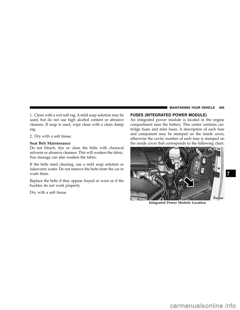
FUSES (INTEGRATED POWER MODULE)
An integrated power module is located in the engine
compartment near the battery. This center contains car-
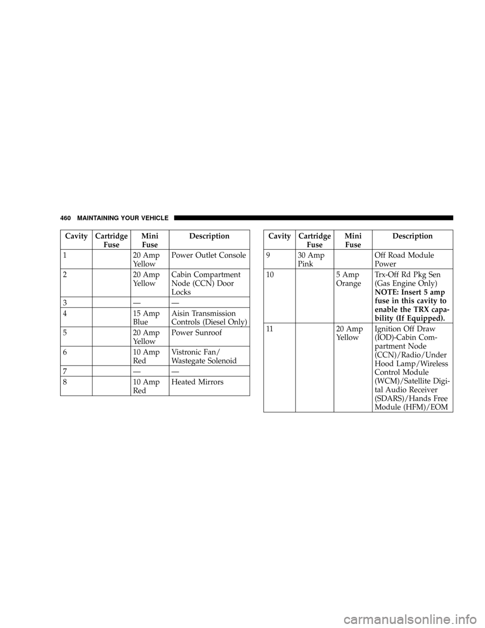
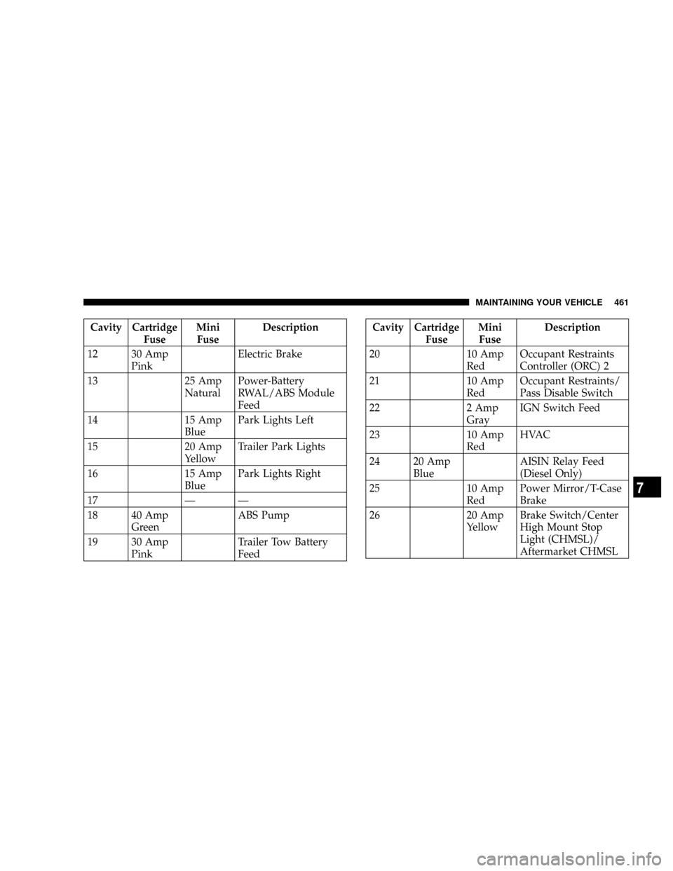
tridge fuses and mini fuses. A description of each fuse
and component may be stamped on the inside cover,
otherwise the cavity number of each fuse is stamped on
the inside cover that corresponds to the following chart.
Integrated Power Module Location
MAINTAINING YOUR VEHICLE 459
7
Page 462 of 527
Cavity Cartridge
FuseMini
FuseDescription
1 20 Amp
YellowPower Outlet Console
2 20 Amp
YellowCabin Compartment
Node (CCN) Door
Locks
3ÐÐ
4 15 Amp
BlueAisin Transmission
Controls (Diesel Only)
5 20 Amp
YellowPower Sunroof
6 10 Amp
RedVistronic Fan/
Wastegate Solenoid
7ÐÐ
8 10 Amp
RedHeated MirrorsCavity Cartridge
FuseMini
FuseDescription
9 30 Amp
PinkOff Road Module
Power
10 5 Amp
OrangeTrx-Off Rd Pkg Sen
(Gas Engine Only)
NOTE: Insert 5 amp
fuse in this cavity to
enable the TRX capa-
bility (If Equipped).
11 20 Amp
YellowIgnition Off Draw
(IOD)-Cabin Com-
partment Node
(CCN)/Radio/Under
Hood Lamp/Wireless
Control Module
(WCM)/Satellite Digi-
tal Audio Receiver
(SDARS)/Hands Free
Module (HFM)/EOM
460 MAINTAINING YOUR VEHICLE
Page 463 of 527
Cavity Cartridge
FuseMini
FuseDescription
12 30 Amp
PinkElectric Brake
13 25 Amp
NaturalPower-Battery
RWAL/ABS Module
Feed
14 15 Amp
BluePark Lights Left
15 20 Amp
YellowTrailer Park Lights
16 15 Amp
BluePark Lights Right
17 Ð Ð
18 40 Amp
GreenABS Pump
19 30 Amp
PinkTrailer Tow Battery
FeedCavity Cartridge
FuseMini
FuseDescription
20 10 Amp
RedOccupant Restraints
Controller (ORC) 2
21 10 Amp
RedOccupant Restraints/
Pass Disable Switch
22 2 Amp
GrayIGN Switch Feed
23 10 Amp
RedHVAC
24 20 Amp
BlueAISIN Relay Feed
(Diesel Only)
25 10 Amp
RedPower Mirror/T-Case
Brake
26 20 Amp
YellowBrake Switch/Center
High Mount Stop
Light (CHMSL)/
Aftermarket CHMSL
MAINTAINING YOUR VEHICLE 461
7
Page 464 of 527
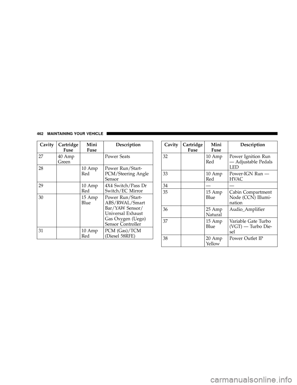
Cavity Cartridge
FuseMini
FuseDescription
27 40 Amp
GreenPower Seats
28 10 Amp
RedPower Run/Start-
PCM/Steering Angle
Sensor
29 10 Amp
Red4X4 Switch/Pass Dr
Switch/EC Mirror
30 15 Amp
BluePower Run/Start-
ABS/RWAL/Smart
Bar/YAW Sensor/
Universal Exhaust
Gas Oxygen (Uego)
Sensor Controller
31 10 Amp
RedPCM (Gas)/TCM
(Diesel 58RFE)Cavity Cartridge
FuseMini
FuseDescription
32 10 Amp
RedPower Ignition Run
Ð Adjustable Pedals
LED
33 10 Amp
RedPower-IGN Run Ð
HVAC
34 Ð Ð
35 15 Amp
BlueCabin Compartment
Node (CCN) Illumi-
nation
36 25 Amp
NaturalAudio_Amplifier
37 15 Amp
BlueVariable Gate Turbo
(VGT) Ð Turbo Die-
sel
38 20 Amp
YellowPower Outlet IP
462 MAINTAINING YOUR VEHICLE
Page 465 of 527
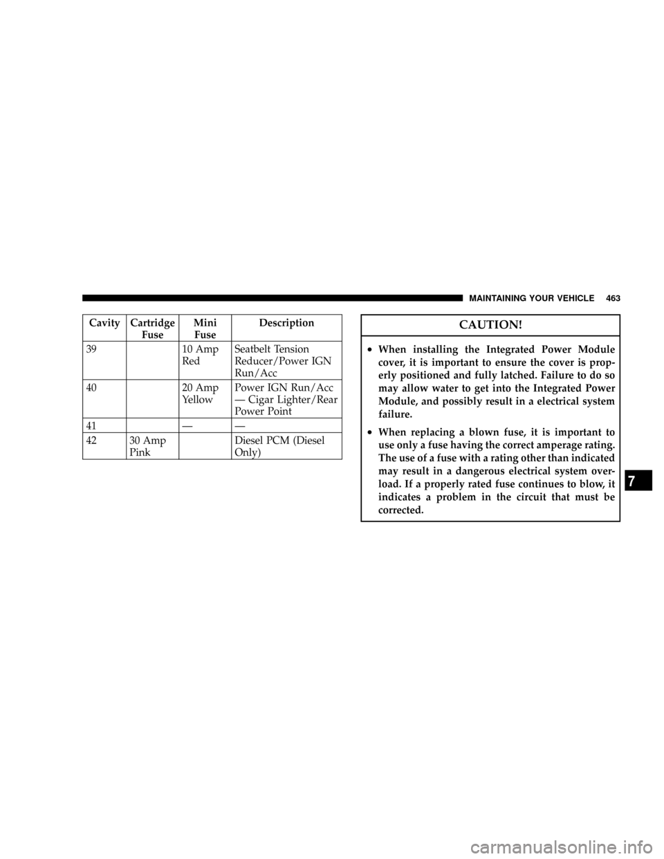
Cavity Cartridge
FuseMini
FuseDescription
39 10 Amp
RedSeatbelt Tension
Reducer/Power IGN
Run/Acc
40 20 Amp
YellowPower IGN Run/Acc
Ð Cigar Lighter/Rear
Power Point
41 Ð Ð
42 30 Amp
PinkDiesel PCM (Diesel
Only)CAUTION!
²When installing the Integrated Power Module
cover, it is important to ensure the cover is prop-
erly positioned and fully latched. Failure to do so
may allow water to get into the Integrated Power
Module, and possibly result in a electrical system
failure.
²When replacing a blown fuse, it is important to
use only a fuse having the correct amperage rating.
The use of a fuse with a rating other than indicated
may result in a dangerous electrical system over-
load. If a properly rated fuse continues to blow, it
indicates a problem in the circuit that must be
corrected.
MAINTAINING YOUR VEHICLE 463
7