engine DODGE RAM 2500 GAS 2008 3.G Owner's Manual
[x] Cancel search | Manufacturer: DODGE, Model Year: 2008, Model line: RAM 2500 GAS, Model: DODGE RAM 2500 GAS 2008 3.GPages: 554, PDF Size: 9.93 MB
Page 169 of 554
The outlet(s) has/have a fused direct feed from the
battery so it/they receive power whether the ignition is
ON or OFF.
All accessories connected to this/these outlet(s) should
be removed or turned OFF when the vehicle is not in use
to protect the battery against discharge.
NOTE:If desired, all of the power outlets can be
converted by your authorized dealer to provide power
with the ignition switch in the ON position only.CAUTION!
Electrical Outlet Use With Engine Off
²Many accessories that can be plugged in draw
power from the vehicle's battery, even when not in
use (i.e., cellular phones, etc.). Eventually, if
plugged in long enough, the vehicle's battery will
discharge sufficiently to degrade battery life
and/or prevent engine starting.
²Accessories that draw higher power (i.e., coolers,
vacuum cleaners, lights, etc.), will discharge the
battery even more quickly. Only use these inter-
mittently and with greater caution.
²After the use of high power draw accessories, or
long periods of the vehicle not being started (with
accessories still plugged in), the vehicle must be
driven a sufficient length of time to allow the
generator to recharge the vehicle's battery.
UNDERSTANDING THE FEATURES OF YOUR VEHICLE 167
3
Page 176 of 554
CAUTION!
²Many accessories that can be plugged in draw
power from the vehicle's battery, even when not in
use (i.e., cellular phones, etc.). Eventually, if
plugged in long enough, the vehicle's battery will
discharge sufficiently to degrade battery life
and/or prevent engine starting.
²Accessories that draw higher power (i.e., coolers,
vacuum cleaners, lights, etc.), will degrade the
battery even more quickly. Only use these inter-
mittently and with greater caution.
²After the use of high power draw accessories, or
long periods of the vehicle not being started (with
accessories still plugged in), the vehicle must be
driven a sufficient length of time to allow the
generator to recharge the vehicle's battery.
Center Storage Compartment (Bucket Seats) ± If
Equipped
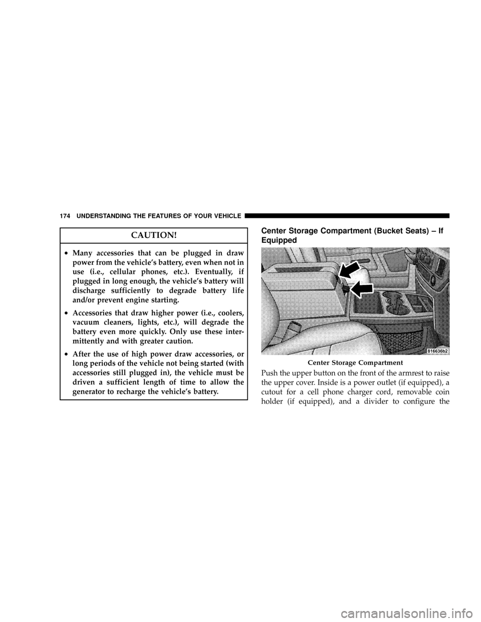
Push the upper button on the front of the armrest to raise
the upper cover. Inside is a power outlet (if equipped), a
cutout for a cell phone charger cord, removable coin
holder (if equipped), and a divider to configure the
Center Storage Compartment
174 UNDERSTANDING THE FEATURES OF YOUR VEHICLE
Page 177 of 554
storage area into separate compartments. Lift the lower
handle on the front of the armrest, and raise the armrest
for access to the lower storage bin. On Quad Cabtand
Mega Cabtmodels the rear of the floor console offers a
power outlet, and a tip out bin.
WARNING!
²This armrest is not a seat. Anyone seated on the
armrest could be seriously injured during vehicle
operation, or an accident. Only use the center
seating position when the armrest is fully upright.
²In an accident, the latch may open if the total
weight of the items stored exceeds about 10 lbs (4.5
kg). These items could be thrown about endanger-
ing occupants of the vehicle. Items stored should
not exceed a total of 10 lbs (4.5 kg).
CAUTION!
²Many accessories that can be plugged in draw
power from the vehicle's battery, even when not in
use (i.e., cellular phones, etc.). Eventually, if
plugged in long enough, the vehicle's battery will
discharge sufficiently to degrade battery life
and/or prevent engine starting.
²Accessories that draw higher power (i.e., coolers,
vacuum cleaners, lights, etc.), will degrade the
battery even more quickly. Only use these inter-
mittently and with greater caution.
²After the use of high power draw accessories, or
long periods of the vehicle not being started (with
accessories still plugged in), the vehicle must be
driven a sufficient length of time to allow the
generator to recharge the vehicle's battery.
UNDERSTANDING THE FEATURES OF YOUR VEHICLE 175
3
Page 198 of 554
INSTRUMENT CLUSTER DESCRIPTION
1. Check Gauges ± Premium Cluster Only
This light illuminates when the Voltmeter, Engine
Oil Pressure or Engine Coolant Temperature
gauges indicate a reading either too high or too low.
Examine the gauges carefully, and follow the instructions
contained below for each indicated problem.
NOTE:When the ignition switch is turned to OFF, the
Fuel Gauge, Voltmeter, Oil Pressure and Engine Coolant
Temperature gauges may not show accurate readings.
When the engine is not running, turn the ignition switch
to ON to obtain accurate readings.
2. Voltmeter
When the engine is running, the gauge indicates
the electrical system voltage. The pointer should
stay within the normal range if the battery is charged. Ifthe pointer moves to either extreme left or right and
remains there during normal driving, the electrical sys-
tem should be serviced.
NOTE:If the gauge pointer moves to either extreme of
the gauge, the ªCheck Gaugesº indicator will illuminate
and a single chime will sound. The ªCheck Gaugesº
indicator may also illuminate prior to the voltage gauge
moving out of normal range. In either case, see you local
authorized Dealer for system service.
3. Turn Signal Indicators
Lights in instrument cluster flash when outside turn
signals are operating.
4. Tachometer
The Tachometer indicates engine speed in revolutions per
minute.
196 UNDERSTANDING YOUR INSTRUMENT PANEL
Page 199 of 554
CAUTION!
Do not operate the engine with the tachometer
pointer at high rpm for extended periods. Engine
damage may occur.
5. Airbag Indicator Light
The indicator lights and remains lit for six to eight
seconds when the ignition is first turned ON. If the light
stays on, flickers or comes on while driving, have the
airbag system checked by an authorized dealer.
6. High Beam Indicator
This indicator shows that headlights are on high
beam.
7. Seat Belt Reminder Light
When the ignition switch is first turned ON, this
light will turn on for five to eight seconds as a bulbcheck. During the bulb check, if the driver's seat belt is
unbuckled, a chime will sound. After the bulb check or
when driving, if the driver's seat belt remains unbuckled,
the Seat Belt Warning Light will flash or remain on
continuously. Refer to9Enhanced Driver Seat Belt Re-
minder System (BeltAlertt)9in the Occupant Restraints
section for more information.(See page 46 for more
information.)
8. Speedometer
The Speedometer shows the vehicle speed in miles per
hour and/or kilometers per hour (mph/kph).
9. Oil Pressure Gauge Ð Premium Cluster Only
The pointer should always indicate some oil pres-
sure when the engine is running. A continuous
high or low reading, under normal driving conditions,
may indicate a lubrication system malfunction. Immedi-
ate service should be obtained from an authorized dealer.
UNDERSTANDING YOUR INSTRUMENT PANEL 197
4
Page 200 of 554
NOTE:If the gauge pointer moves to either extreme of
the gauge, the ªCheck Gaugesº indicator will illuminate
and a single chime will sound.
10. Transfer Case Position
This display indicator shows the transfer case position
selection.
For additional information refer to ª4-Wheel Drive Op-
erationº in section 5 of this manual.
11. TOW HAUL
The TOW HAUL button is located at the end of the gear
shift lever. This light will illuminate when the TOW
HAUL OD/OFF button is pushed once.
12. OD/OFF
The OD/OFF button is located at the end of the gear shift
lever. This light will illuminate when the TOW HAUL
OD/OFF button is pushed twice.13. Temperature Gauge
The Temperature Gauge indicates engine coolant
temperature. Any reading within the normal
range indicates that the cooling system is operat-
ing satisfactorily. The gauge needle will likely indicate a
higher temperature when driving in hot weather, up
mountain grades, in heavy traffic, or when towing a
trailer. If the needle rises to the ª245É F (118É C)º mark,
stop the vehicle, shift into NEUTRAL, and increase the
engine idle speed for two to three minutes. If the tem-
perature reading does not return to normal, shut your
engine OFF and allow it to cool. Seek authorized service
immediately. Refer to ªCooling Systemº under ªMain-
taining Your Vehicleº in section 7.
198 UNDERSTANDING YOUR INSTRUMENT PANEL
Page 201 of 554
CAUTION!
Do not leave your vehicle unattended with the en-
gine running as you would not be able to react to the
temperature indicator if the engine overheats.
NOTE:Engine idle speed will automatically increase to
1000 rpm at elevated coolant temperatures to improve
engine cooling.
NOTE:If the gauge pointer moves to either extreme of
the gauge, the ªCheck Gaugesº indicator will illuminate
and a single chime will sound.
14. Security Light
This light will flash rapidly for approximately 15 seconds
when the Vehicle Security Alarm is arming. The light will
flash at a slower speed continuously after the alarm is set.
The Security light will also come on for about three
seconds when the ignition is first turned on.15. Transmission Range Indicator (Automatic
Transmissions Only)
When the gear selector lever is moved, this indicator
shows the automatic transmission gear range selected.
16. Odometer/Trip Odometer
The odometer shows the total distance the vehicle has
been driven. U.S. federal regulations require that upon
transfer of vehicle ownership, the seller certify to the
purchaser the correct mileage that the vehicle has been
driven. Therefore, if the odometer reading is changed
during repair or replacement, be sure to keep a record of
the reading before and after the service so that the correct
mileage can be determined.
The two trip odometers show individual trip mileage. To
switch from odometer to trip odometers, press and
release the Trip Odometer button.
UNDERSTANDING YOUR INSTRUMENT PANEL 199
4
Page 202 of 554
To reset a trip odometer, display the desired trip odom-
eter to be reset then push and hold the button until the
display resets (approximately two seconds).
Vehicle Warning Messages
When the appropriate conditions exist, messages such as
ªdoorº (indicates that a door(s) may be ajar), ªhoodº (if
the hood is open or ajar, on vehicles with remote start),
ªgASCAPº (which indicates that your gas cap is possibly
loose or damaged),9CHANgE OILº (indicates that the
engine oil should be change), ªLoWASHº (low washer
fluid), ªESPOFFº (indicates that ESP is turned off), and
ªnoFUSEº (indicates that the IOD fuse is removed from
the Integrated Power Module), will display in the odom-
eter.
NOTE:There is also an engine hour function. This
indicates the total number of hours the engine has been
running. To display the engine hours perform the follow-
ing: Place the ignition in RUN, but do not start theengine. With the odometer value displayed, hold the trip
button down for a period of six seconds. The odometer
will change to trip value first, then it will display the
engine hour value. The engine hours will be displayed
for a period of 30 seconds until the ignition is turned OFF
or the engine is started.
Change Oil Message
Your vehicle is equipped with an engine oil change
indicator system. The ªCHANgE OILº message will flash
in the instrument cluster odometer for approximately 12
seconds after a single chime has sounded to indicate the
next scheduled oil change interval. The engine oil change
indicator system is duty cycle based, which means the
engine oil change interval may fluctuate dependent upon
your personal driving style.
Unless reset, this message will continue to display each
time you turn the ignition switch to the ON/RUN
position. To turn off the message temporarily, press and
200 UNDERSTANDING YOUR INSTRUMENT PANEL
Page 203 of 554
release the Trip Odometer button on the instrument
cluster. To reset the oil change indicator system (after
performing the scheduled maintenance) refer to the fol-
lowing procedure.
1. Turn the ignition switch to the ON position(Do not
start the engine).
2. Fully depress the accelerator pedal slowly three
times within 10 seconds.
3. Turn the ignition switch to the OFF/LOCK position.
NOTE:If the indicator message illuminates when you
start the vehicle, the oil change indicator system did not
reset. If necessary repeat this procedure.
17. Front Fog Light Indicator Ð If Equipped
This light shows when the front fog lights are ON.18. Malfunction Indicator Light
This light is part of an onboard diagnostic system
which monitors the emissions and engine control
system. If the vehicle is ready for emissions
testing, the light will come on when the ignition is first
turned on and remain on, as a bulb check, until the
engine is started. If the vehicle is not ready for emissions
testing the light will come on when the ignition is first
turned on and remain on for 15 seconds, then blink for 5
seconds, and remain on until the vehicle is started. If the
bulb does not come on during starting, have the condi-
tion investigated promptly.
If this light comes on and remains on while driving, it
suggests a potential engine control problem and the need
for system service.
Although your vehicle will usually be drivable and not
need towing, see your authorized dealer for service as
soon as possible.
UNDERSTANDING YOUR INSTRUMENT PANEL 201
4
Page 204 of 554
CAUTION!
Prolonged driving with the MIL on could cause
damage to the engine control system. It also could
affect fuel economy and drivability.
If the MIL is flashing, severe catalytic converter
damage and power loss will soon occur. Immediate
service is required.
19. Brake System Warning Light
This light illuminates when the ignition key is turned to
the ON position and remains on for a few seconds. If the
light stays on longer, it may be an indication that the
parking brake has not been released. This light will
illuminate if the brake fluid is low, especially when
braking or accelerating hard. This light will illuminate if
the ABS indicator light has a malfunction. This light will
flash if the engine is running and the parking brake is on.If the light remains on when the parking brake is
released, it indicates a possible brake hydraulic system
malfunction. In this case, the light will remain on until
the cause is corrected.
If brake failure is indicated, immediate repair is necessary
and continued operation of the vehicle in this condition is
dangerous.
Acceleration which causes the rear wheels to slip for a
period of time may result in the red brake light illumi-
nating and a brake switch code being set on ABS
equipped vehicles. Depressing the brake pedal should
extinguish the red brake light.
20. ABS Warning Light
This light monitors the Anti-Lock Brake System
which is described elsewhere in this manual. This
light will come on when the ignition key is turned to the
ON position and may stay on for five seconds. If the ABS
light remains on or comes on during driving, it indicates
202 UNDERSTANDING YOUR INSTRUMENT PANEL