set DODGE RAM 4500 CHASSIS CAB 2009 4.G Repair Manual
[x] Cancel search | Manufacturer: DODGE, Model Year: 2009, Model line: RAM 4500 CHASSIS CAB, Model: DODGE RAM 4500 CHASSIS CAB 2009 4.GPages: 429, PDF Size: 7.19 MB
Page 204 of 429
The right-hand control is a rocker type switch with a
button in the center. Pressing the top of the switch will
increase the volume and pressing the bottom of the
switch will decrease the volume. The center button of the
right-hand control will allow you to change the mode.
The left-hand control is a rocker type switch with a push
button in the center. The function of the left-hand control
is different, depending on which mode you are in.
The following describes the left-hand control operation in
each mode.
Radio Operation
Pressing the top of the left side switch will seek up for the
next listenable station and pressing the bottom of the
switch will seek down for the next listenable station.
The button located in the center of the left-hand control
will tune to the next pre-set station that you have
programmed in the radio pre-set push-buttons.
Tape Player
Pressing the top of the switch once will go to the next
selection on the cassette. Pressing the bottom of the
switch once will go to the beginning of the current
selection or to the beginning of the previous selection if it
is within the first five seconds of the current selection.
If you press the switch up or down twice it plays the
second selection; three times, it will play the third, etc.
The button in the center of the left-hand switch has no
function in this mode.
CD Player
Pressing the top of the switch once will go to the next
track on the CD. Pressing the bottom of the switch once
will go to the beginning of the current track or to the
beginning of the previous track if it is within one second
after the current track; begins to play.
202 UNDERSTANDING YOUR INSTRUMENT PANEL
Page 206 of 429
CLIMATE CONTROLS
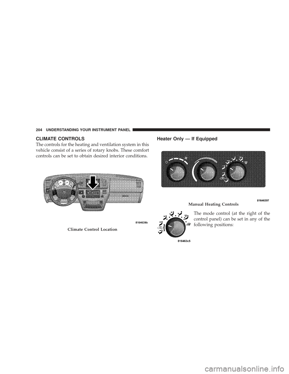
The controls for the heating and ventilation system in this
vehicle consist of a series of rotary knobs. These comfort
controls can be set to obtain desired interior conditions.
Heater Only — If Equipped
The mode control (at the right of the
control panel) can be set in any of the
following positions:
Climate Control Location
Manual Heating Controls
204 UNDERSTANDING YOUR INSTRUMENT PANEL
Page 208 of 429
Blower Control
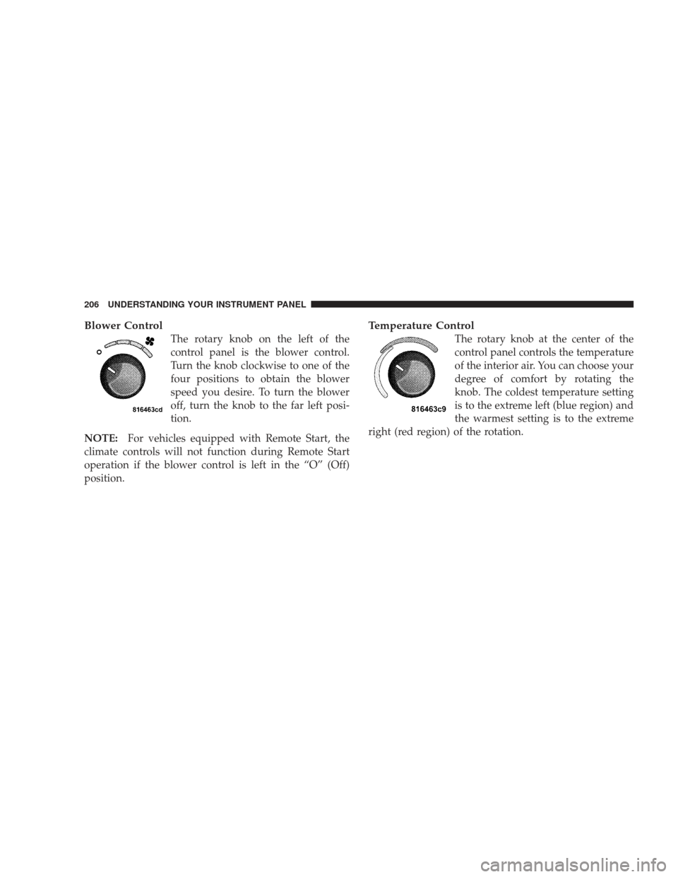
The rotary knob on the left of the
control panel is the blower control.
Turn the knob clockwise to one of the
four positions to obtain the blower
speed you desire. To turn the blower
off, turn the knob to the far left posi-
tion.
NOTE: For vehicles equipped with Remote Start, the
climate controls will not function during Remote Start
operation if the blower control is left in the “O” (Off)
position.
Temperature Control
The rotary knob at the center of the
control panel controls the temperature
of the interior air. You can choose your
degree of comfort by rotating the
knob. The coldest temperature setting
is to the extreme left (blue region) and
the warmest setting is to the extreme
right (red region) of the rotation.
206 UNDERSTANDING YOUR INSTRUMENT PANEL
Page 209 of 429
Air Conditioning and Heating — If Equipped
Air Conditioning Operation
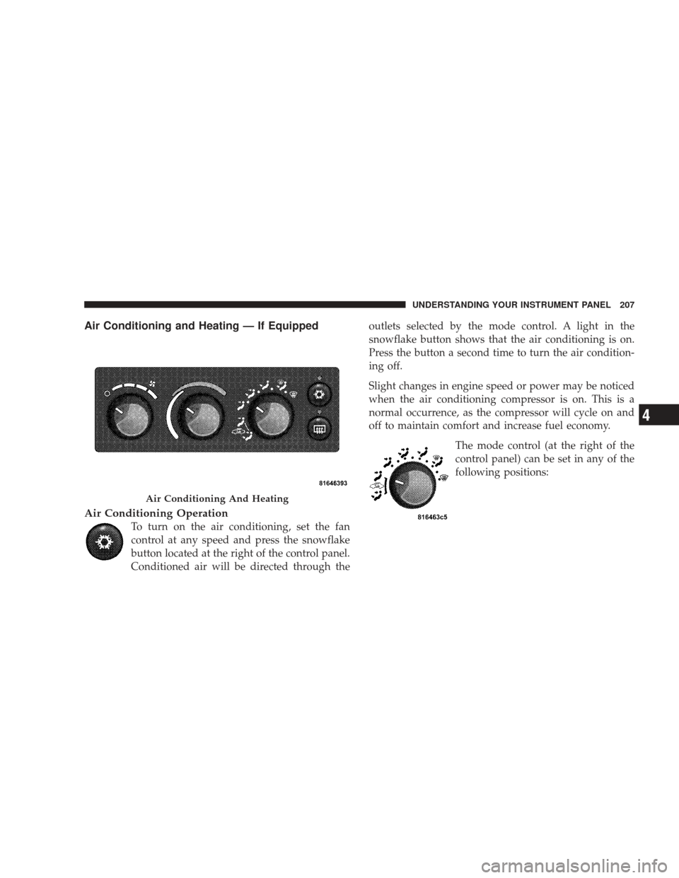
To turn on the air conditioning, set the fan
control at any speed and press the snowflake
button located at the right of the control panel.
Conditioned air will be directed through theoutlets selected by the mode control. A light in the
snowflake button shows that the air conditioning is on.
Press the button a second time to turn the air condition-
ing off.
Slight changes in engine speed or power may be noticed
when the air conditioning compressor is on. This is a
normal occurrence, as the compressor will cycle on and
off to maintain comfort and increase fuel economy.
The mode control (at the right of the
control panel) can be set in any of the
following positions:
Air Conditioning And Heating
UNDERSTANDING YOUR INSTRUMENT PANEL 207
4
Page 211 of 429
Blower Control
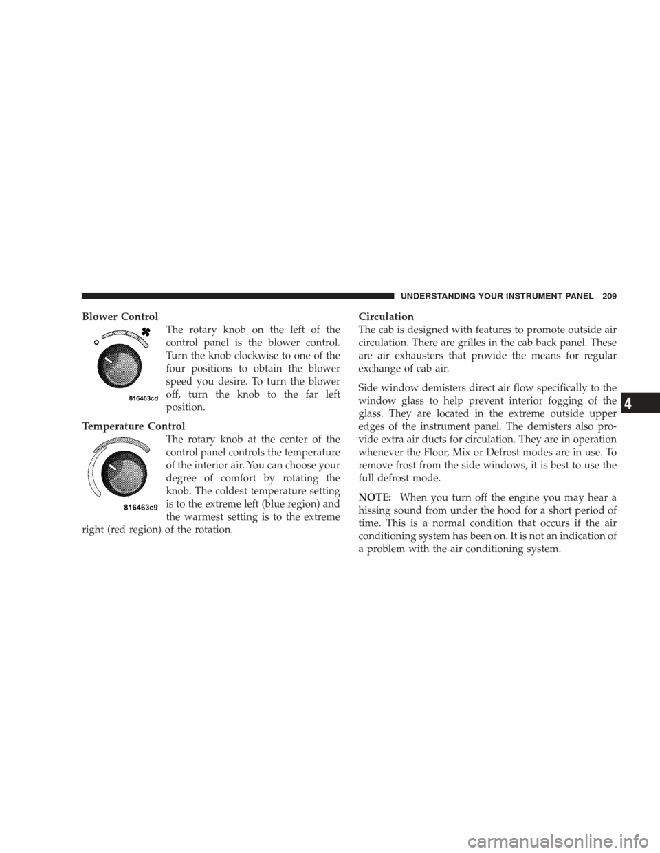
The rotary knob on the left of the
control panel is the blower control.
Turn the knob clockwise to one of the
four positions to obtain the blower
speed you desire. To turn the blower
off, turn the knob to the far left
position.
Temperature Control
The rotary knob at the center of the
control panel controls the temperature
of the interior air. You can choose your
degree of comfort by rotating the
knob. The coldest temperature setting
is to the extreme left (blue region) and
the warmest setting is to the extreme
right (red region) of the rotation.
Circulation
The cab is designed with features to promote outside air
circulation. There are grilles in the cab back panel. These
are air exhausters that provide the means for regular
exchange of cab air.
Side window demisters direct air flow specifically to the
window glass to help prevent interior fogging of the
glass. They are located in the extreme outside upper
edges of the instrument panel. The demisters also pro-
vide extra air ducts for circulation. They are in operation
whenever the Floor, Mix or Defrost modes are in use. To
remove frost from the side windows, it is best to use the
full defrost mode.
NOTE: When you turn off the engine you may hear a
hissing sound from under the hood for a short period of
time. This is a normal condition that occurs if the air
conditioning system has been on. It is not an indication of
a problem with the air conditioning system.
UNDERSTANDING YOUR INSTRUMENT PANEL 209
4
Page 212 of 429
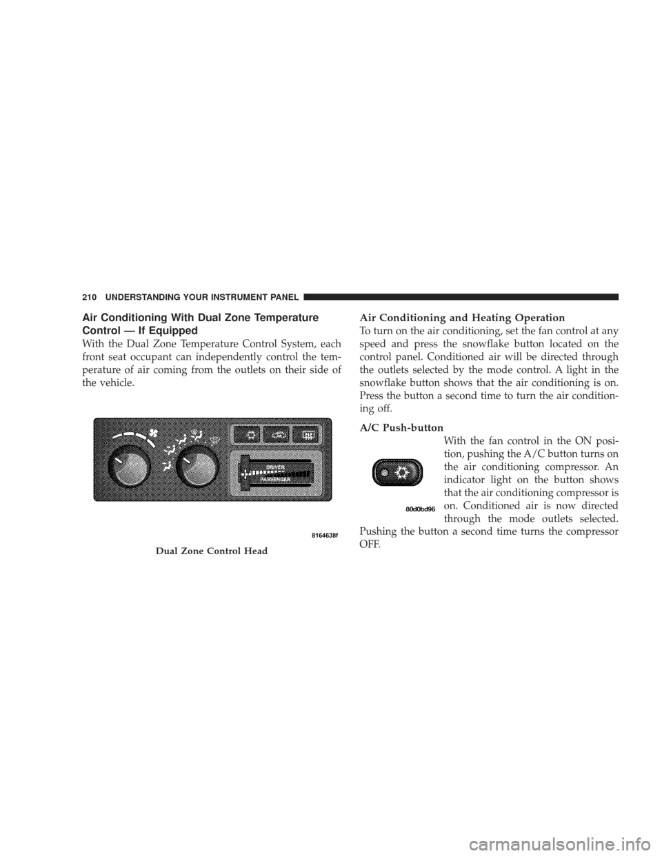
Air Conditioning With Dual Zone Temperature
Control — If Equipped
With the Dual Zone Temperature Control System, each
front seat occupant can independently control the tem-
perature of air coming from the outlets on their side of
the vehicle.
Air Conditioning and Heating Operation
To turn on the air conditioning, set the fan control at any
speed and press the snowflake button located on the
control panel. Conditioned air will be directed through
the outlets selected by the mode control. A light in the
snowflake button shows that the air conditioning is on.
Press the button a second time to turn the air condition-
ing off.
A/C Push-button
With the fan control in the ON posi-
tion, pushing the A/C button turns on
the air conditioning compressor. An
indicator light on the button shows
that the air conditioning compressor is
on. Conditioned air is now directed
through the mode outlets selected.
Pushing the button a second time turns the compressor
OFF.
Dual Zone Control Head
210 UNDERSTANDING YOUR INSTRUMENT PANEL
Page 227 of 429
DRIVE position. Pull the shift lever toward you when
shifting into REVERSE, SECOND, FIRST or PARK, or
when shifting out of PARK.
Gear Ranges
DO NOT race the engine when shifting from PARK or
NEUTRAL position into another gear range.
PARK
This gear position supplements the parking brake by
locking the transmission. The engine can be started in
this range. Never use PARK while the vehicle is in
motion. Apply the parking brake when leaving the
vehicle in this range. Always apply parking brake first,
then place the shift lever into the PARK position. On
4-wheel drive vehicles be sure that the transfer case is in
a drive position!
WARNING!
•Never use the PARK position as a substitute for
the parking brake. Always apply parking brake
fully when parked to guard against vehicle move-
ment and possible injury or damage.
•Your vehicle could move and injure you and others
if it is not completely in PARK. Check by trying to
move the shift lever back and forth without first
pulling it toward you after you have set it in
PARK. Make sure it is in PARK before leaving the
vehicle.(Continued)
STARTING AND OPERATING 225
5
Page 228 of 429
WARNING! (Continued)
•It is dangerous to move the shift lever out of PARK
or NEUTRAL if the engine speed is higher than
idle speed. If your foot is not firmly on the brake
pedal, the vehicle could accelerate quickly forward
or in reverse. You could lose control of the vehicle
and hit someone or something. Only shift into
gear when the engine is idling normally and when
your right foot is firmly on the brake pedal.
REVERSE
Use this range only after the vehicle has come to a
complete stop.
NEUTRAL
Shift into NEUTRAL when the vehicle is standing for
prolonged periods with the engine running. The engine
may be started in this range. Set the parking brake if you
must leave the vehicle. DRIVE
This position provides all forward gears, including 3rd
gear direct and 4th or 5th gear overdrive (see Overdrive
Operation). Use this range for most city and highway
driving.
SECOND
Use this position for driving slowly in heavy city traffic
or on mountain roads where more precise speed control
is desirable. Use it also when climbing long grades, and
for engine braking when descending moderately steep
grades. To prevent excessive engine speed do not exceed
45 mph (72 km/h) in this range.
FIRST
Use this position for driving up very steep hills and for
engine braking at low speeds 20 mph (32 km/h) or less
when going downhill. To prevent excessive engine speed,
do not exceed 25 mph (40 km/h) in this range.
226 STARTING AND OPERATING
Page 256 of 429
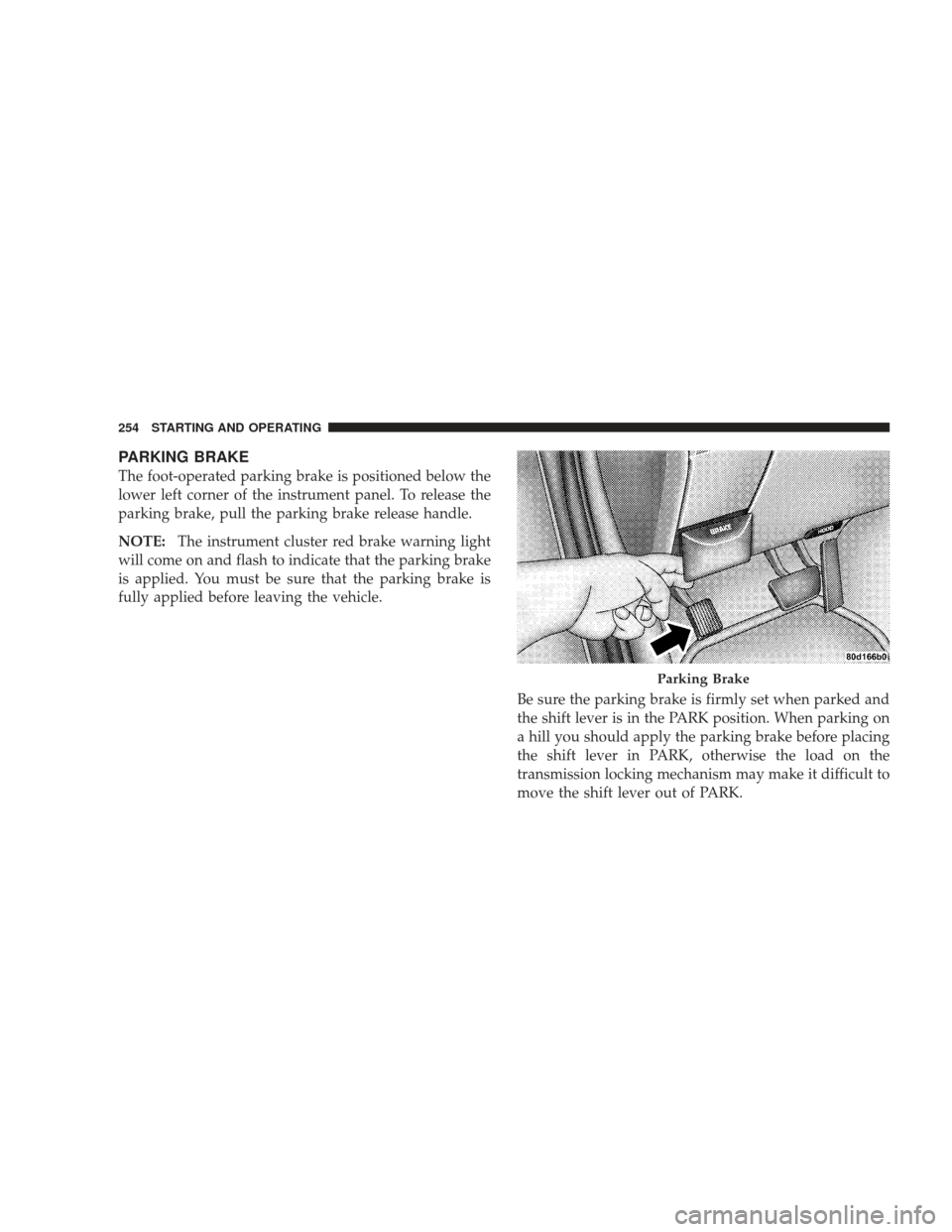
PARKING BRAKE
The foot-operated parking brake is positioned below the
lower left corner of the instrument panel. To release the
parking brake, pull the parking brake release handle.
NOTE:The instrument cluster red brake warning light
will come on and flash to indicate that the parking brake
is applied. You must be sure that the parking brake is
fully applied before leaving the vehicle.
Be sure the parking brake is firmly set when parked and
the shift lever is in the PARK position. When parking on
a hill you should apply the parking brake before placing
the shift lever in PARK, otherwise the load on the
transmission locking mechanism may make it difficult to
move the shift lever out of PARK.
Parking Brake
254 STARTING AND OPERATING
Page 274 of 429
WARNING!
High speed driving with your vehicle under maxi-
mum load is dangerous. The added strain on your
tires could cause them to fail. You could have a
serious accident resulting in serious injury or death.
Don’t drive a vehicle loaded to the maximum capac-
ity at continuous speeds above 75 mph (120 km/h).
Radial Ply Tires
WARNING!
Combining radial ply tires with other types of tires
on your vehicle will cause your vehicle to handle
poorly. The instability could cause an accident result-
ing in serious injury or death. Always use radial ply
tires in sets of four (or six, in case of trucks with dual
rear wheels). Never combine them with other types
of tires.
Cuts and punctures in radial tires are repairable only in
the tread area because of sidewall flexing. Consult your
authorized tire dealer for radial tire repairs.
272 STARTING AND OPERATING