wiring DODGE RAM SRT-10 2006 Service Repair Manual
[x] Cancel search | Manufacturer: DODGE, Model Year: 2006, Model line: RAM SRT-10, Model: DODGE RAM SRT-10 2006Pages: 5267, PDF Size: 68.7 MB
Page 5048 of 5267
4.ACTUATOR DTC DETECTION TEST
NOTE: The Actuator DTC Detection Test clears all door actuator related DTCs when the test is actuated.
If not done so previously, start the engine.
With the scan tool, select System Tests and then select Actuator DTC Detection. When the test is complete, select
View DTCs.
Does the scan tool display any DTCs?
Yes, Dual-Zone
Diagnose and repair the DTC(s). If multiple DTCs are present, beginning with the passenger blend door,
diagnose and repair all short high DTCs and then all short low DTCs. Refer tothe Table of Contents in
this Section for a complete list of HVAC related symptoms.
Yes, Single-Zone
Diagnose and repair the DTC(s). If multiple DTCs are present, beginning with the common circuit, diag-
nose and repair all short high DTCs and then all short low DTCs. Refer to the Table of Contents in this
Section for a complete list of HVAC related symptoms.
No>>
If you are here due to a stored DTC, it is possible that a technician may not have erased the DTC
following a repair. If possible, verify if the vehicle was recently in for this type of service. Otherwise,
either Go To 5 or visually inspect the related wiring harness for chafed, pierced, pinched, and partially
broken wires and the wiring harness connectors for broken, bent, pushed out, and corroded terminals,
and repair as necessary.
Perform BODY VERIFICATION TEST - VER 1. (Refer to 8 - ELECTRICAL/ELECTRONIC CONTROL
MODULES - STANDARD PROCEDURE).
5.ACTUATOR CALIBRATION TEST
NOTE: For vehicles equipped with EBL, running the HVAC Door Recalibrationwill cause the EBL status
indicator to flash.
NOTE: The Actuator Calibration Test clears all door actuator related DTCswhen the test is actuated.
If not done so previously, start the engine.
With the scan tool, select System Tests and then select Actuator Calibration Test. When the test is complete, select
View DTCs.
Does the scan tool display any DTCs?
Ye s>>
Diagnose and repair the DTC(s). Refer to the Table of Contents in this Section for a complete list of
HVAC related symptoms.
No>>
No problem found. However, if you are here due to a stored DTC, it is possiblethat a technician may
not have erased the DTC following a repair. If possible, verify if the vehicle was recently in for this type
of service. Otherwise, visually inspect the related wiring harness for chafed, pierced, pinched, and par-
tially broken wires and the wiring harness connectors for broken, bent, pushed out, and corroded ter-
minals, and repair as necessary.
Perform BODY VERIFICATION TEST - VER 1. (Refer to 8 - ELECTRICAL/ELECTRONIC CONTROL
MODULES - STANDARD PROCEDURE).
Page 5057 of 5267
Improper heater hose routing.
Plugged heater hoses or supply and return ports at the cooling system connections.
Plugged heater core.
If proper coolant flow through the cooling system is verified, and heater outlet air temperature is low, a mechanical
problem may exist.
MECHANICAL PROBLEMS
Possible locations or causes of insufficient heat due to mechanical problems are as follows:
Obstructed cowl air intake.
Obstructed heater system outlets.
Blend-air door(s) or actuator(s) not functioning properly.
Faulty blower motor system
Faulty A/C-heater control
TEMPERATURE CONTROL
If the heater outlet air temperature cannot be adjusted with the temperature control on the A/C-heater control, the
following could require service:
Faulty A/C-heater control.
Faulty blend door actuator(s).
Faulty, obstructed or improperly installed blend-air door.
Faulty related wiring harness or connectors.
Improper engine coolant temperature.
SPECIFICATIONS
A/C SYSTEM
Item Description Notes
A/C Compressor Denso 10S17 (3.7L/4.7L/5.7L/8.3L
engines)ND-8 PAG oil
Visteon HS-18 (5.9L engine) VC-46 PAG oil
Freeze–up Control Evaporator Temperature Sensor A/C evaporator mounted
High psi Control A/C pressure transducer A/C discharge line mounted
Refrigerant Charge Capacity Refer to the A/C Underhood
Specification Label located in the
engine compartment.R134a refrigerant
A/C Clutch Field Coil Draw 3.2 - 3.3 amps @ 12V ± 0.5V @
21° C (70° F)3.7L/4.7L/5.7L/8.3L engines
3.1 - 4 amps @ 12V ± 0.5V @ 21°
C(70°F)5.9L engine
A/C Clutch Air Gap 0.35 - 0.60 mm (0.014 - 0.024 in.) 3.7L/4.7L/5.7L/8.3L engines
0.35 - 0.75 mm (0.014 - 0.030 in.) 5.9L engine
TORQUE
Page 5086 of 5267
RESISTOR-BLOWER MOTOR
DESCRIPTION
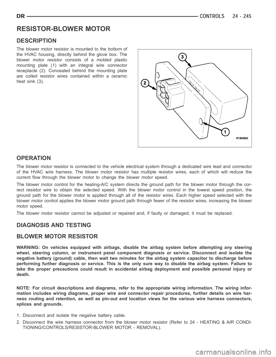
The blower motor resistor is mounted to the bottom of
the HVAC housing, directly behind the glove box. The
blower motor resistor consists of a molded plastic
mounting plate (1) with an integral wire connector
receptacle (2). Concealed behind the mounting plate
are coiled resistor wires contained within a ceramic
heat sink (3).
OPERATION
The blower motor resistor is connected to the vehicle electrical system through a dedicated wire lead and connector
of the HVAC wire harness. The blower motor resistor has multiple resistor wires, each of which will reduce the
current flow through the blower motor to change the blower motor speed.
The blower motor control for the heating-A/C system directs the ground path for the blower motor through the cor-
rect resistor wire to obtain the selected speed. With the blower motor control in the lowest speed position, the
ground path for the blower motor is applied through all of the resistor wires. Each higher speed selected with the
blower motor control applies the blower motor ground path through fewer ofthe resistor wires, increasing the blower
motor speed.
The blower motor resistor cannot be adjusted or repaired and, if faulty or damaged, it must be replaced.
DIAGNOSIS AND TESTING
BLOWER MOTOR RESISTOR
WARNING: On vehicles equipped with airbags, disable the airbag system before attempting any steering
wheel, steering column, or instrument panel component diagnosis or service. Disconnect and isolate the
negative battery (ground) cable, then wait two minutes for the airbag system capacitor to discharge before
performing further diagnosis or service. This is the only sure way to disable the airbag system. Failure to
take the proper precautions could result in accidental airbag deploymentand possible personal injury or
death.
NOTE: For circuit descriptions and diagrams, refer to the appropriate wiring information. The wiring infor-
mation includes wiring diagrams, proper wire and connector repair procedures, further details on wire har-
ness routing and retention, as well as pin-out and location views for the various wire harness connectors,
splices and grounds.
1. Disconnect and isolate the negative battery cable.
2. Disconnect the wire harness connector from the blower motor resistor (Refer to 24 - HEATING & AIR CONDI-
TIONING/CONTROLS/RESISTOR-BLOWER MOTOR - REMOVAL).
Page 5107 of 5267
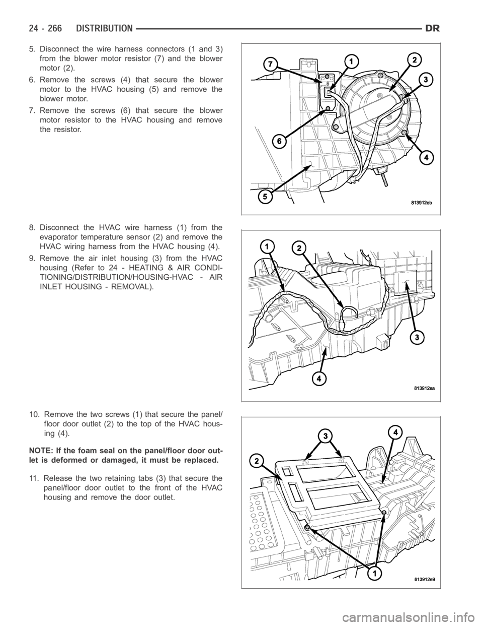
5. Disconnect the wire harness connectors (1 and 3)
from the blower motor resistor (7) and the blower
motor (2).
6. Remove the screws (4)that secure the blower
motor to the HVAC housing (5) and remove the
blower motor.
7. Remove the screws (6)that secure the blower
motor resistor to the HVAC housing and remove
the resistor.
8. Disconnect the HVAC wire harness (1) from the
evaporator temperature sensor (2) and remove the
HVAC wiring harness from the HVAC housing (4).
9. Remove the air inlet housing (3) from the HVAC
housing (Refer to 24 - HEATING & AIR CONDI-
TIONING/DISTRIBUTION/HOUSING-HVAC - AIR
INLET HOUSING - REMOVAL).
10. Remove the two screws (1) that secure the panel/
floor door outlet (2) to the top of the HVAC hous-
ing (4).
NOTE: If the foam seal on the panel/floor door out-
let is deformed or damaged, it must be replaced.
11. Release the two retaining tabs (3) that secure the
panel/floor door outlet to the front of the HVAC
housing and remove the door outlet.
Page 5117 of 5267
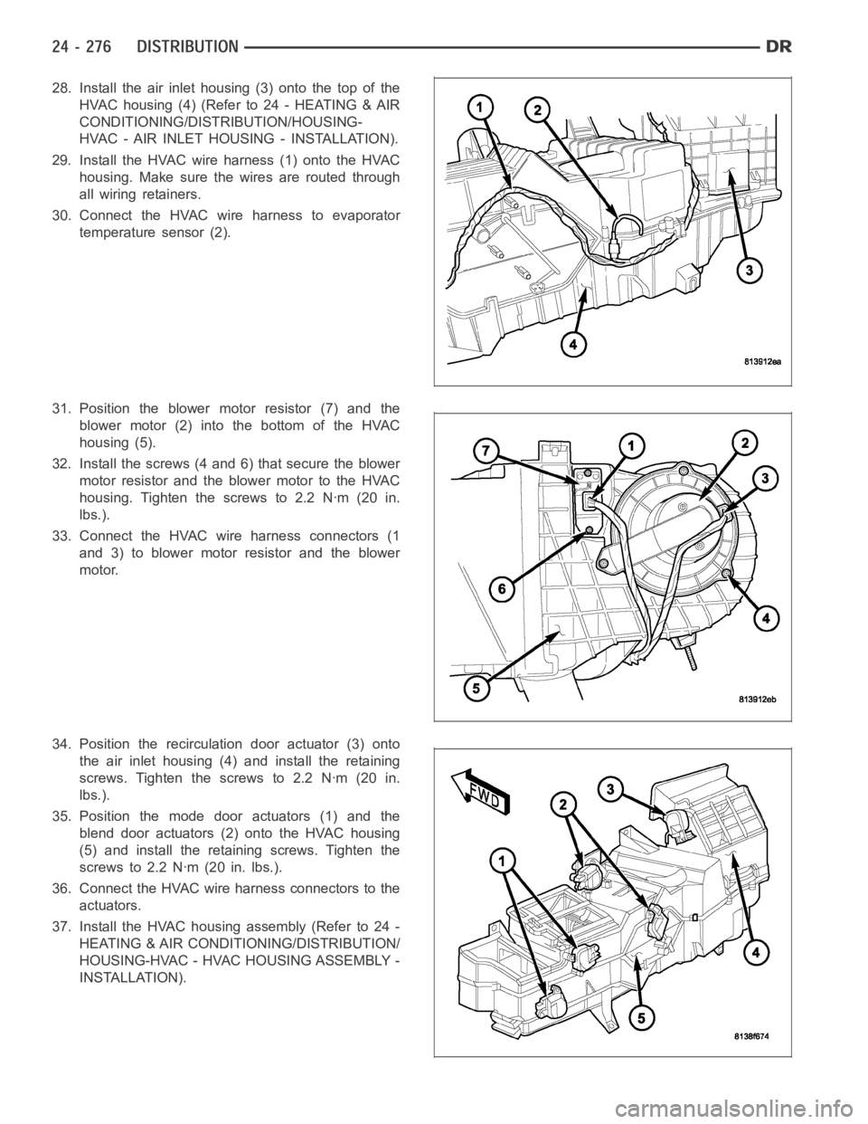
28. Install the air inlet housing (3) onto the top of the
HVAC housing (4) (Refer to 24 - HEATING & AIR
CONDITIONING/DISTRIBUTION/HOUSING-
HVAC - AIR INLET HOUSING - INSTALLATION).
29. Install the HVAC wire harness (1) onto the HVAC
housing. Make sure the wires are routed through
all wiring retainers.
30. Connect the HVAC wire harness to evaporator
temperature sensor (2).
31. Position the blower motor resistor (7) and the
blower motor (2) into the bottom of the HVAC
housing (5).
32. Install the screws (4 and 6) that secure the blower
motor resistor and the blower motor to the HVAC
housing. Tighten the screws to 2.2 Nꞏm (20 in.
lbs.).
33. Connect the HVAC wire harness connectors (1
and 3) to blower motor resistor and the blower
motor.
34. Position the recirculation door actuator (3) onto
the air inlet housing (4) and install the retaining
screws. Tighten the screws to 2.2 Nꞏm (20 in.
lbs.).
35. Position the mode door actuators (1) and the
blend door actuators (2) onto the HVAC housing
(5) and install the retaining screws. Tighten the
screws to 2.2 Nꞏm (20 in. lbs.).
36. Connect the HVAC wire harness connectors to the
actuators.
37. Install the HVAC housing assembly (Refer to 24 -
HEATING & AIR CONDITIONING/DISTRIBUTION/
HOUSING-HVAC - HVAC HOUSING ASSEMBLY -
INSTALLATION).
Page 5122 of 5267
NOTE: The blower motor is supplied with a 12V feed from the TIPM, through theresistor block, whenever
the ignition switch is in the RUN position. Due to an open circuit conditionwithin the blower motor control
switch the TIPM is UNABLE to detect an OPEN circuit for the blower motor.
To determine if an open condition exists within the blower motor circuit wiring, it is necessary to disconnect the
negative battery cable and check for continuity within the blower motor circuits using an ohmmeter. For circuit
descriptions and diagrams, refer to Air Conditioning/Heater in Group 8W -Wiring Diagrams.
OPERATION
Possible causes of the blower motor not operating include:
Faulty blower motor
Faulty blower motor circuit wiring or wire harness connectors
Faulty blower motor control
Possible causes of the blower motor not operating in one or more speeds include:
Faulty blower motor resistor
Faulty blower motor circuit wiring or wire harness connectors
Faulty blower motor control
VIBRATION
Possible causes of blower motor vibration include:
Improper blower motor mounting
Improper blower wheel mounting
Deformed blower wheel
Out of balance blower wheel due to foreign material in the wheel
Faulty blower motor
NOISE
To determine if the blower motor is the source of the noise, simply switch the blower motor from Off to On. To verify
that the blower motor is the source of the noise, unplug the blower motor wire harness connector and operate the
heating-A/C system. If the noise goes away, possible causes include:
Foreign material in the HVAC air inlet housing
Improper blower motor mounting
Improper blower wheel mounting
Faulty blower motor
Page 5193 of 5267
EMISSIONS CONTROL
DESCRIPTION
STATE DISPLAY TEST MODE
The switch inputs to the Powertrain Control Module (PCM) have two recognized states; HIGH and LOW. For this
reason, the PCM cannot recognize the difference between a selected switchposition versus an open circuit, a short
circuit, or a defective switch. If the State Display screen shows the changefromHIGHtoLOWorLOWtoHIGH,
assume the entire switch circuit to the PCM functions properly. Connect the DRB scan tool to the data link con-
nector and access the state display screen. Then access either State Display Inputs and Outputs or State Display
Sensors.
CIRCUIT ACTUATION TEST MODE
The Circuit Actuation Test Mode checks for proper operation of output circuits or devices the Powertrain Control
Module (PCM) may not internally recognize. The PCM attempts to activate these outputs and allow an observer to
verify proper operation. Most of the tests provide an audible or visual indication of device operation (click of relay
contacts, fuel spray, etc.). Except for intermittent conditions, if a device functions properly during testing, assume the
device, its associated wiring, and driver circuit work correctly. Connect the DRB scan tool to the data link connector
and access the Actuators screen.
DIAGNOSTIC TROUBLE CODES
A Diagnostic Trouble Code (DTC) indicates the PCM has recognized an abnormal condition in the system.
Remember that DTC’s are the results of a system or circuit failure, but do not directly identify the failed
component or components.
BULB CHECK
Each time the ignition key is turned to the ON position, the malfunction indicator (check engine) lamp on the instru-
ment panel should illuminate for approximately 2 seconds then go out. Thisis done for a bulb check.
OBTAINING DTC’S USING DRB SCAN TOOL
1. Obtain the applicable Powertrain Diagnostic Manual.
2. Obtain the DRB Scan Tool.
3. Connect the DRB Scan Tool to the data link (diagnostic) connector. This connector is located in the passenger
compartment at the lower edge of instrument panel, and near the steering column.
4. Turn the ignition switch on and access the “Read Fault” screen.
5. Record all the DTC’s and “freeze frame” information shown on the DRB scantool.
6. To erase DTC’s, use the “Erase Trouble Code” data screen on the DRB scan tool.Do not erase any DTC’s
until problems have been investigated and repairs have been performed.
TA S K M A N A G E R
The PCM is responsible for efficiently coordinating the operation of all the emissions-related components. The PCM
is also responsible for determining if the diagnostic systems are operating properly. The software designed to carry
out these responsibilities is called the ’Task Manager’.
MONITORED SYSTEMS
There are new electronic circuit monitors that check fuel, emission, engine and ignition performance. These moni-
tors use information from various sensor circuits to indicate the overalloperation of the fuel, engine, ignition and
emission systems and thus the emissions performance of the vehicle.
The fuel, engine, ignition and emission systems monitors do not indicate aspecific component problem. They do
indicate that there is an implied problem within one of the systems and thata specific problem must be diagnosed.
If any of these monitors detect a problem affecting vehicle emissions, theMalfunction Indicator Lamp (MIL) will be
illuminated. These monitors generate Diagnostic Trouble Codes that can be displayed with the MIL or a scan tool.
Page 5205 of 5267
SOLENOID-EVAP/PURGE
DESCRIPTION
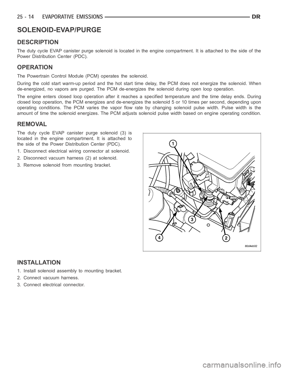
The duty cycle EVAP canister purge solenoid is located in the engine compartment. It is attached to the side of the
Power Distribution Center (PDC).
OPERATION
The Powertrain Control Module (PCM) operates the solenoid.
During the cold start warm-up period and the hot start time delay, the PCM does not energize the solenoid. When
de-energized, no vapors are purged. The PCM de-energizes the solenoid during open loop operation.
The engine enters closed loop operation after it reaches a specified temperature and the time delay ends. During
closed loop operation, the PCM energizes and de-energizes the solenoid 5 or 10 times per second, depending upon
operating conditions. The PCM varies the vapor flow rate by changing solenoid pulse width. Pulse width is the
amount of time the solenoid energizes. The PCM adjusts solenoid pulse width based on engine operating condition.
REMOVAL
The duty cycle EVAP canister purge solenoid (3) is
located in the engine compartment. It is attached to
the side of the Power Distribution Center (PDC).
1. Disconnect electrical wiring connector at solenoid.
2. Disconnect vacuum harness (2) at solenoid.
3. Remove solenoid from mounting bracket.
INSTALLATION
1. Install solenoid assembly to mounting bracket.
2. Connect vacuum harness.
3. Connect electrical connector.