battery DODGE RAM SRT-10 2006 Service Repair Manual
[x] Cancel search | Manufacturer: DODGE, Model Year: 2006, Model line: RAM SRT-10, Model: DODGE RAM SRT-10 2006Pages: 5267, PDF Size: 68.7 MB
Page 583 of 5267

4.(K139) WASTEGATE SOLENOID DRIVER CIRCUIT OPEN
Disconnect the ECM harness connectors.
Measure the resistance of the Wastegate Solenoid driver circuit
between the Wastegate Solenoid harness connector and the ECM har-
ness connector.
Is the resistance less than 10 Ohms?
Ye s>>
Go To 5
No>>
Repair the open (K139) Wastegate Solenoid control circuit.
Perform POWERTRAIN VERIFICATION TEST VER - 1
(DIESEL). (Refer to 8 - ELECTRICAL/ELECTRONIC CON-
TROL MODULES/ENGINE CONTROL MODULE - DIAG-
NOSIS AND TESTING)
5.(K139) WASTEGATE SOLENOID CIRCUIT SHORTED TO GROUND
Measure the resistance of the (K139) Wastegate Solenoid driver circuit
between the Wastegate Solenoid harness connector and battery nega-
tive.
Is the resistance less than 10 Ohms?
Ye s>>
Repair the (K139) Wastegate solenoid circuit shorted to
ground.
Perform POWERTRAIN VERIFICATION TEST VER - 1
(DIESEL). (Refer to 8 - ELECTRICAL/ELECTRONIC CON-
TROL MODULES/ENGINE CONTROL MODULE - DIAG-
NOSIS AND TESTING)
No>>
Go To 6
Page 584 of 5267

6.(K139) WASTEGATE SOLENOID DRIVER SHORTED TO VOLTAGE
Measure the voltage between the (K139) Wastegate Solenoid driver cir-
cuit at the Wastegate Solenoid connector and battery negative.
Is the voltage less than 1 volt?
Ye s>>
Go To 7
No>>
Repair the (K139) Wastegate solenoid driver shorted to volt-
age.
Perform POWERTRAIN VERIFICATION TEST VER - 1
(DIESEL). (Refer to 8 - ELECTRICAL/ELECTRONIC CON-
TROL MODULES/ENGINE CONTROL MODULE - DIAG-
NOSIS AND TESTING)
7.(K139) WASTEGATE SOLENOID DRIVER CIRCUIT SHORTED TO ANOTHER CIRCUIT
Measure the resistance between the (K139) Wastegate Solenoid driver
circuit in the ECM harness connector and all other circuits in the ECM
harness connectors.
Is the resistance less than 10 Ohms?
Ye s>>
Repair the (K139) Wastegate solenoid circuit shorted to
another circuit.
Perform POWERTRAIN VERIFICATION TEST VER - 1
(DIESEL).
No>>
Go To 8
Page 587 of 5267
When Monitored:
When the ignition is on.
Set Condition:
The ECM detects a discrepancy between the PWM supplied to the Electronic Fuel Control Actuator and the
PWM returned from the Electronic Fuel Control Actuator.
Possible Causes
FUEL PUMP
(K181) FUEL CONTROL ACTUATOR DRIVER OPEN
(K31) RETURN CIRCUIT OPEN FROM FCA TO ECM
(K181) FUEL CONTROL ACTUATOR DRIVER CIRCUIT SHORTED TO EXTERNAL VOLTAGE
(K31) FUEL CONTROL ACTUATOR RETURN CIRCUIT SHORTED TO EXTERNAL VOLTAGE
(K31) FCA RETURN CIRCUIT SHORTED TO (K181) FCA DRIVER CIRCUIT
(K181) FUEL CONTROL ACTUATOR DRIVER CIRCUIT SHORTED TO GROUND
(K181) FUEL CONTROL ACTUATOR DRIVER CIRCUIT SHORTED TO ANOTHER CIRCUIT
(K31) FUEL CONTROL ACTUATOR RETURN CIRCUIT SHORTED TO ANOTHER CIRCUIT
INTERMITTENT CONDITION
ECM
Always perform the Pre-Diagnostic Troubleshooting procedure before proceeding. (Refer to 9 - ENGINE -
DIAGNOSIS AND TESTING)
Diagnostic Test
1.FUEL PUMP
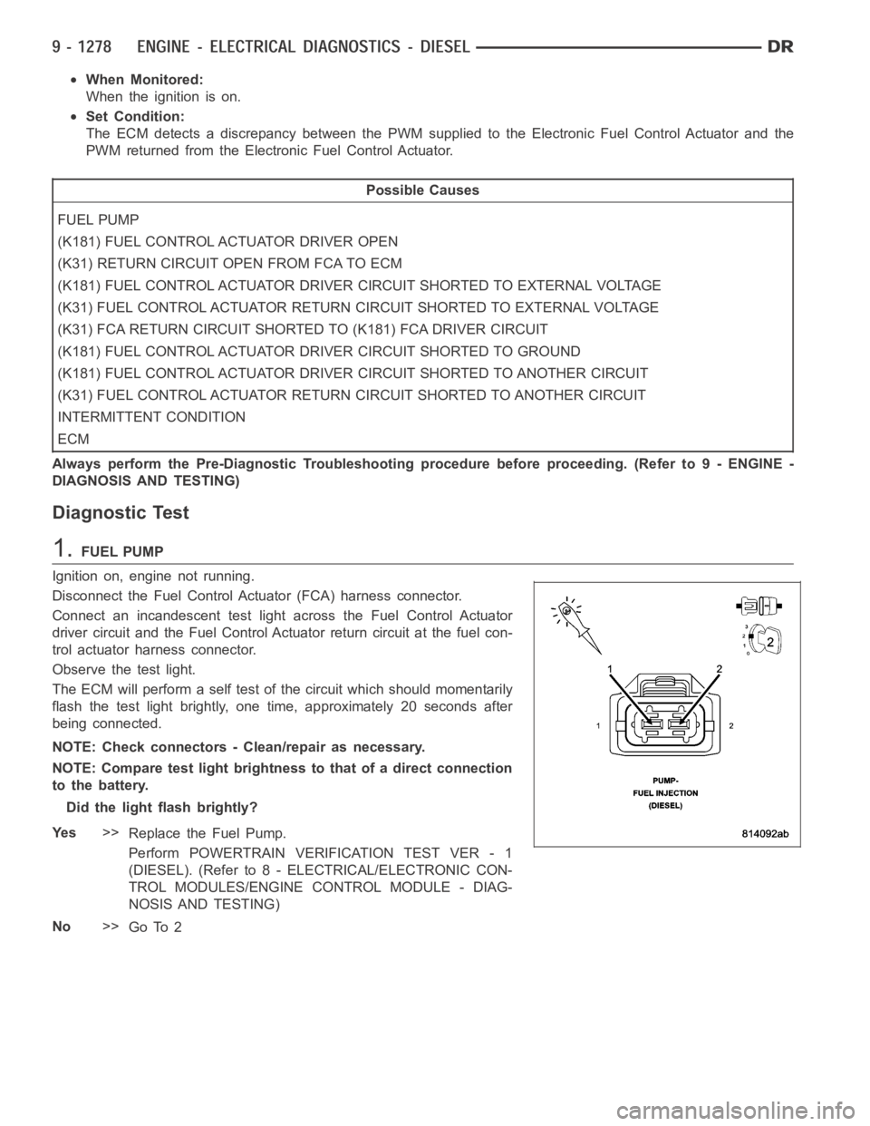
Ignition on, engine not running.
Disconnect the Fuel Control Actuator (FCA) harness connector.
Connect an incandescent test light across the Fuel Control Actuator
driver circuit and the Fuel Control Actuator return circuit at the fuel con-
trol actuator harness connector.
Observe the test light.
The ECM will perform a self test of the circuit which should momentarily
flash the test light brightly, one time, approximately 20 seconds after
being connected.
NOTE: Check connectors - Clean/repair as necessary.
NOTE: Compare test light brightness to that of a direct connection
to the battery.
Did the light flash brightly?
Ye s>>
Replace the Fuel Pump.
Perform POWERTRAIN VERIFICATION TEST VER - 1
(DIESEL). (Refer to 8 - ELECTRICAL/ELECTRONIC CON-
TROL MODULES/ENGINE CONTROL MODULE - DIAG-
NOSIS AND TESTING)
No>>
Go To 2
Page 589 of 5267

4.(K181) FUEL CONTROL ACTUATOR DRIVER CIRCUIT SHORTED TO EXTERNAL VOLTAGE
Measure the voltage between the (K181) FCA driver circuit in the FCA
harness connector and battery negative.
Is the voltage greater than 1 volts?
Ye s>>
Repair the (K181) FCA driver circuit shorted to external volt-
age.
No>>
Go To 5
5.(K31) FUEL CONTROL ACTUATOR RETURN CIRCUIT SHORTED TO EXTERNAL VOLTAGE
Measure the voltage between the (K31) FCA return circuit in the FCA
harness connector and battery negative.
Is the voltage greater than 1 volts?
Ye s>>
Repair the (K31) FCA return circuit shorted to external volt-
age.
Perform POWERTRAIN VERIFICATION TEST VER - 1
(DIESEL). (Refer to 8 - ELECTRICAL/ELECTRONIC CON-
TROL MODULES/ENGINE CONTROL MODULE - DIAG-
NOSIS AND TESTING)
No>>
Go To 6
6.(K31) FCA RETURN CIRCUIT SHORTED TO (K181) FCA DRIVER CIRCUIT
Measure the Resistance between the return circuit in the FCA harness
connector and Driver circuit.
Is the resistance less than 10 Ohms?
Ye s>>
Repair the (K31) FCA Return circuit shorted to (K181) FCA
Driver circuit.
Perform POWERTRAIN VERIFICATION TEST VER - 1
(DIESEL). (Refer to 8 - ELECTRICAL/ELECTRONIC CON-
TROL MODULES/ENGINE CONTROL MODULE - DIAG-
NOSIS AND TESTING)
No>>
Go To 7
Page 590 of 5267

7.(K181) FUEL CONTROL ACTUATOR DRIVER CIRCUIT SHORTED TO GROUND
Measure the resistance between the (K181) FCA driver circuit in the
FCA harness connector and battery negative.
Is the resistance less than 10 Ohms?
Ye s>>
Repair the (K181) FCA driver circuit shorted to ground.
Perform POWERTRAIN VERIFICATION TEST VER - 1
(DIESEL). (Refer to 8 - ELECTRICAL/ELECTRONIC CON-
TROL MODULES/ENGINE CONTROL MODULE - DIAG-
NOSIS AND TESTING)
No>>
Go To 8
8.(K181) FUEL CONTROL ACTUATOR DRIVER CIRCUIT SHORTED TO ANOTHER CIRCUIT
Measure the resistance between the (K181) FCA driver circuit in the
ECM harness connector and all other circuits in the ECM connectors.
Is the resistance less than 10 Ohms?
No>>
Go To 9
Ye s>>
Repair the (K181) FCA driver circuit shorted to another cir-
cuit.
Perform POWERTRAIN VERIFICATION TEST VER - 1
(DIESEL). (Refer to 8 - ELECTRICAL/ELECTRONIC CON-
TROL MODULES/ENGINE CONTROL MODULE - DIAG-
NOSIS AND TESTING)
9.(K31) FUEL CONTROL ACTUATOR RETURN CIRCUIT SHORTED TO ANOTHER CIRCUIT
Measure the resistance between the (K31) FCA Return circuit in the
ECM harness connector and all other circuits in the ECM connectors.
Is the resistance less than 10 Ohms?
No>>
Go To 10
Ye s>>
Repair the (K31) FCA Return circuit shorted to another cir-
cuit.
Perform POWERTRAIN VERIFICATION TEST VER - 1
(DIESEL). (Refer to 8 - ELECTRICAL/ELECTRONIC CON-
TROL MODULES/ENGINE CONTROL MODULE - DIAG-
NOSIS AND TESTING)
Page 591 of 5267

10.ECM
Reconnect the ECM harness connectors.
Ignition on, engine not running.
Disconnect the Electronic Fuel Control Actuator connector.
Connect an incandescent test light across the Fuel Control Actuator
driver pin and the Fuel Control Actuator return wire at the fuel control
actuator connector.
Observe the test light.
The ECM will perform a self test of the circuit which should momentarily
flash the test light brightly, one time, approximately 20 seconds after
being connected.
NOTE: Compare test light brightness to that of a direct connection
to the battery.
Did the light flash brightly?
Ye s>>
Refer to the INTERMITTENT CONDITION Symptom (Diag-
nostic Procedure). (Refer to 9 - ENGINE - DIAGNOSIS
AND TESTING)
No>>
Replace the ECM.
Perform POWERTRAIN VERIFICATION TEST VER - 1 (DIESEL). (Refer to 8 - ELECTRICAL/ELEC-
TRONIC CONTROL MODULES/ENGINE CONTROL MODULE - DIAGNOSIS AND TESTING)
Page 617 of 5267

When Monitored:
While the engine is running.
Set Condition:
The ECM no longer detects a signal from the Crankshaft Position Sensor.
Possible Causes
OTHER DTC’S
P0337 PRESENT
CKP SENSOR
VISUAL DAMAGE
(K24) SIGNAL CIRCUIT OPEN
(K853) 5-VOLT SUPPLY CIRCUIT OPEN
(K167) RETURN CIRCUIT OPEN
(K24) SIGNAL CIRCUIT SHORTED TO (K975) RETURN CIRCUIT
(K853) 5-VOLT SUPPLY CIRCUIT SHORTED TO (K975) RETURN CIRCUIT
(K24) SIGNAL CIRCUIT SHORTED TO(K853) 5-VOLT SUPPLY CIRCUIT
(K24) SIGNAL CIRCUIT SHORTED TO GROUND
(K853) 5-VOLT SUPPLY CIRCUIT SHORTED TO BATTERY NEGATIVE
INTERMITTENT CONDITION
ECM
Always perform the Pre-Diagnostic Troubleshooting procedure before proceeding. (Refer to 9 - ENGINE -
DIAGNOSIS AND TESTING)
Diagnostic Test
1.OTHER DTC’S
With the scan tool, read DTCs.
Is DTC P2146 and/or P2149 present?
Ye s>>
Repair other DTC’s.
Perform POWERTRAIN VERIFICATION TEST VER - 1 (DIESEL). (Refer to 8 - ELECTRICAL/ELEC-
TRONIC CONTROL MODULES/ENGINE CONTROL MODULE - DIAGNOSIS AND TESTING)
No>>
Go To 2
2.P0337 PRESENT
With the scan tool, read DTCs.
Is P0337 present?
Ye s>>
Repair P0337 first.
Perform POWERTRAIN VERIFICATION TEST VER - 1 (DIESEL). (Refer to 8 - ELECTRICAL/ELEC-
TRONIC CONTROL MODULES/ENGINE CONTROL MODULE - DIAGNOSIS AND TESTING)
No>>
Go To 3
Page 623 of 5267
When Monitored:
With the key on.
Set Condition:
The voltage detected at the Crankshaft position sensor is below a calibrated value.
Possible Causes
CKP SENSOR
(K24) SIGNAL CIRCUIT OPEN
(K853) 5-VOLT SUPPLY CIRCUIT OPEN
(K975) RETURN CIRCUIT OPEN
(K24) SIGNAL CIRCUIT SHORTED TO (K975) RETURN CIRCUIT
(K853) 5-VOLT SUPPLY CIRCUIT SHORTED TO (K975) RETURN CIRCUIT
(K24) SIGNAL CIRCUIT SHORTED TO(K853) 5-VOLT SUPPLY CIRCUIT
(K24) SIGNAL CIRCUIT SHORTED TO GROUND
(K853) 5-VOLT SUPPLY CIRCUIT SHORTED TO BATTERY NEGATIVE
INTERMITTENT CONDITION
ECM
Always perform the Pre-Diagnostic Troubleshooting procedure before proceeding. (Refer to 9 - ENGINE -
DIAGNOSIS AND TESTING)
Diagnostic Test
1.CKP SENSOR
Disconnect the CKP sensor harness connector.
NOTE: Check connectors - Clean/repair as necessary.
Measure the resistance between the (K853) 5-volt supply circuit and the (K24) signal circuit of the sensor.
Is the resistance between 900 and 1100 ohms?
Ye s>>
Go To 2
No>>
Replace the CKP sensor.
Perform POWERTRAIN VERIFICATION TEST VER - 1 (DIESEL). (Refer to 8 - ELECTRICAL/ELEC-
TRONIC CONTROL MODULES/ENGINE CONTROL MODULE - DIAGNOSIS AND TESTING)
Page 629 of 5267
When Monitored:
With the key on.
Set Condition:
Voltage detected at the CKP is below acalibrated value for a calibrated amountoftime.
Possible Causes
CKP SENSOR
(K853) 5-VOLT SUPPLY CIRCUIT SHORTED TO (K975) RETURN CIRCUIT
(K853) 5-VOLT SUPPLY CIRCUIT SHORTED BATTERY NEGATIVE
INTERMITTENT CONDITION
ECM
Always perform the Pre-Diagnostic Troubleshooting procedure before proceeding. (Refer to 9 - ENGINE -
DIAGNOSIS AND TESTING)
Diagnostic Test
1.CKP SENSOR
Disconnect the CKP sensor harness connector.
Check connectors - Clean/repair as necessary.
Measure the resistance between the (K853) 5-volt supply circuit and the (K24) signal circuit of the sensor.
Is the resistance between 900 and 1100 ohms?
Ye s>>
Go To 2
No>>
Replace the CKP sensor.
Perform POWERTRAIN VERIFICATION TEST VER - 1 (DIESEL). (Refer to 8 - ELECTRICAL/ELEC-
TRONIC CONTROL MODULES/ENGINE CONTROL MODULE - DIAGNOSIS AND TESTING)
2.(K853) 5-VOLT SUPPLY CIRCUIT SHORTED TO (K975) RETURN CIRCUIT
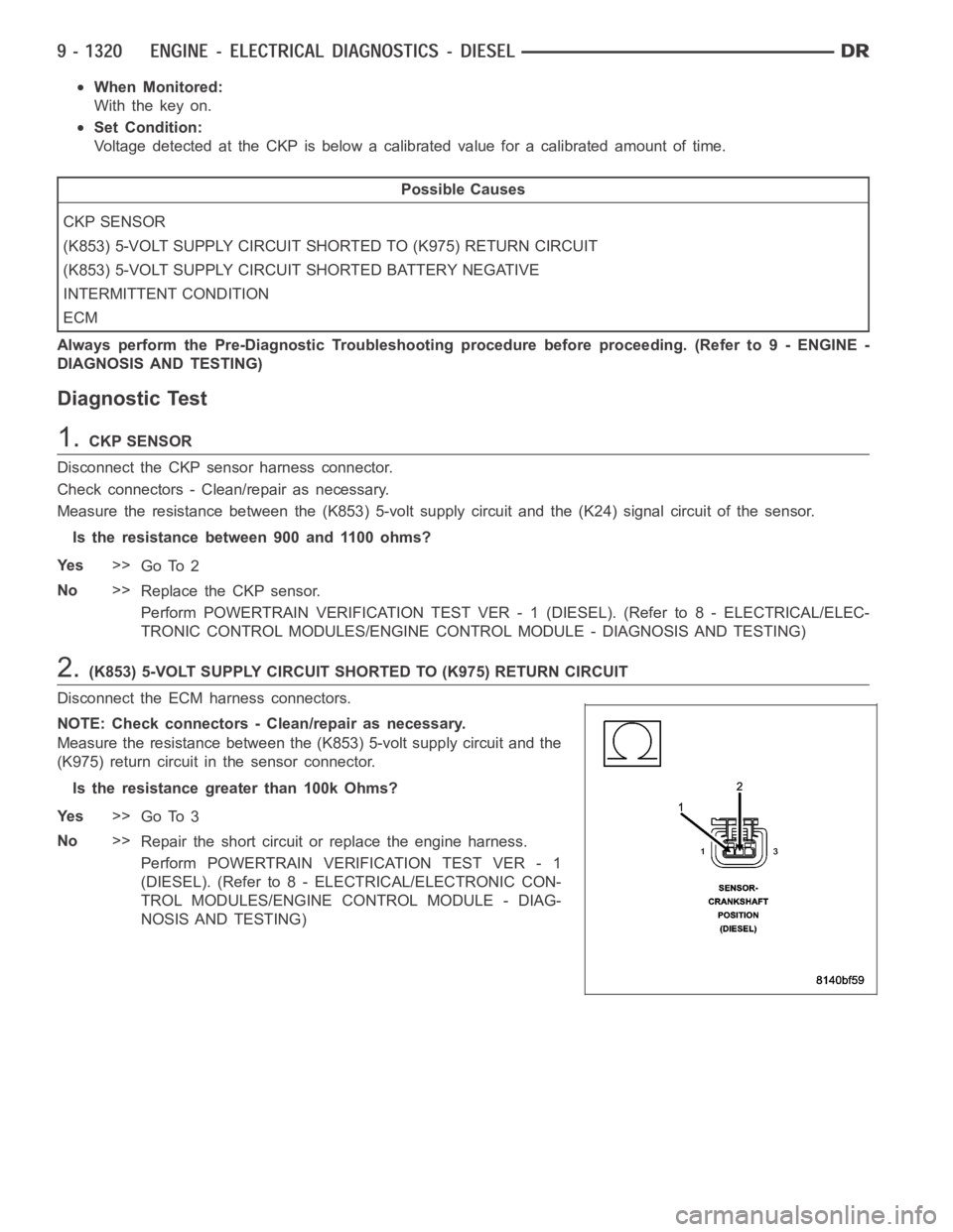
Disconnect the ECM harness connectors.
NOTE: Check connectors - Clean/repair as necessary.
Measure the resistance between the (K853) 5-volt supply circuit and the
(K975) return circuit in the sensor connector.
Is the resistance greater than 100k Ohms?
Ye s>>
Go To 3
No>>
Repair the short circuit or replace the engine harness.
Perform POWERTRAIN VERIFICATION TEST VER - 1
(DIESEL). (Refer to 8 - ELECTRICAL/ELECTRONIC CON-
TROL MODULES/ENGINE CONTROL MODULE - DIAG-
NOSIS AND TESTING)
Page 630 of 5267

3.(K853) 5-VOLT SUPPLY CIRCUIT SHORTED BATTERY NEGATIVE
Measure the resistance between the (K853) 5-volt supply circuit and
battery negative.
Is the resistance greater than 100k Ohms?
Ye s>>
Go To 4
No>>
Repair the short circuit or replace the engine harness.
Perform POWERTRAIN VERIFICATION TEST VER - 1
(DIESEL). (Refer to 8 - ELECTRICAL/ELECTRONIC CON-
TROL MODULES/ENGINE CONTROL MODULE - DIAG-
NOSIS AND TESTING)
4.ECM
Reconnect the ECM harness connectors.
Ignition on, engine not running.
Connect a jumper wire between the sensor (K853) 5-volt supply circuit
in the sensor harness connector 12-volts.
Did DTC P0338 set?
Ye s>>
Refer to the INTERMITTENT CONDITION Symptom (Diag-
nostic Procedure). (Refer to 9 - ENGINE - DIAGNOSIS
AND TESTING)
No>>
Replace the ECM.
Perform POWERTRAIN VERIFICATION TEST VER - 1
(DIESEL). (Refer to 8 - ELECTRICAL/ELECTRONIC CON-
TROL MODULES/ENGINE CONTROL MODULE - DIAG-
NOSIS AND TESTING)