battery DODGE RAM SRT-10 2006 Service Repair Manual
[x] Cancel search | Manufacturer: DODGE, Model Year: 2006, Model line: RAM SRT-10, Model: DODGE RAM SRT-10 2006Pages: 5267, PDF Size: 68.7 MB
Page 433 of 5267
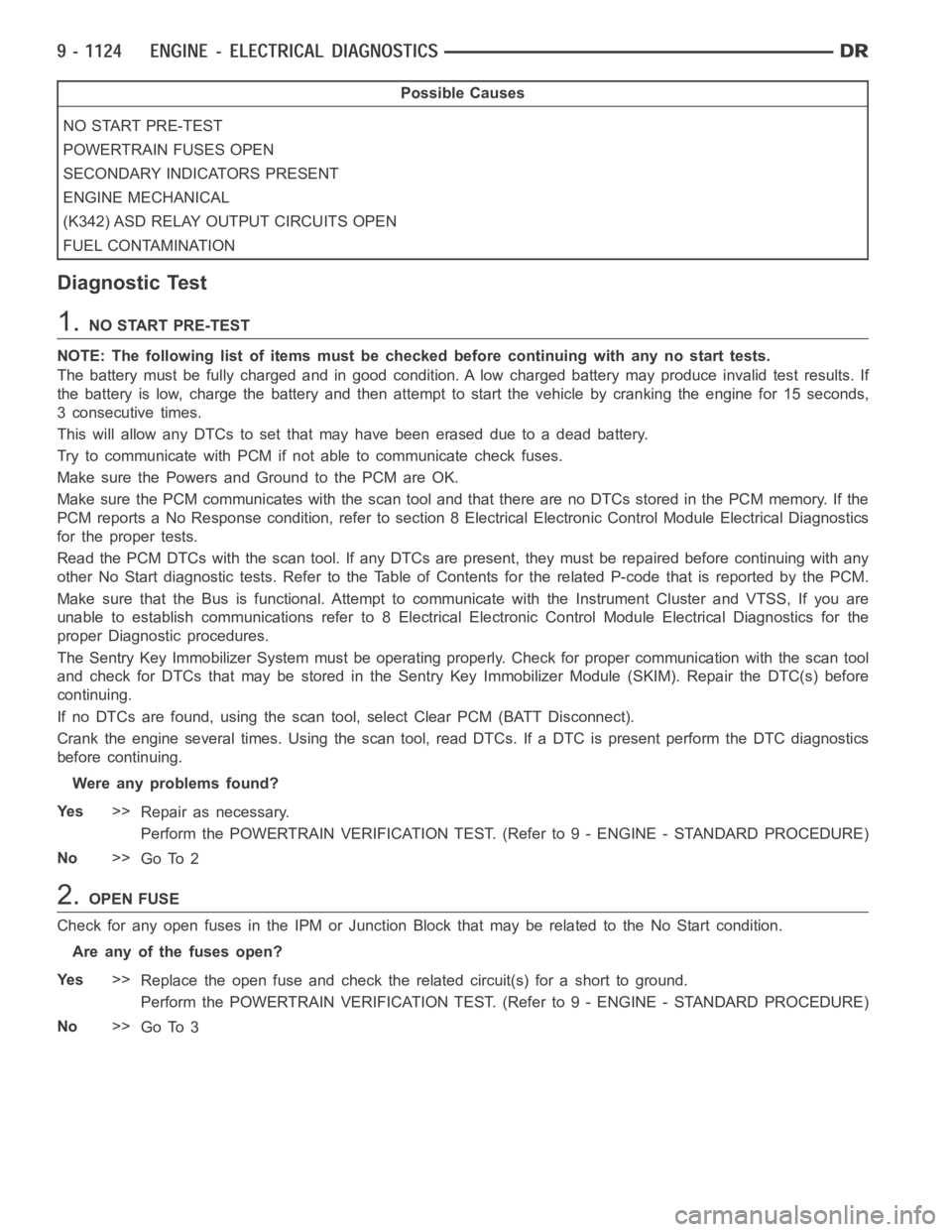
Possible Causes
NO START PRE-TEST
POWERTRAIN FUSES OPEN
SECONDARY INDICATORS PRESENT
ENGINE MECHANICAL
(K342) ASD RELAY OUTPUT CIRCUITS OPEN
FUEL CONTAMINATION
Diagnostic Test
1.NO START PRE-TEST
NOTE: The following list of items must be checked before continuing with any no start tests.
The battery must be fully charged and in good condition. A low charged battery may produce invalid test results. If
the battery is low, charge the battery and then attempt to start the vehicleby cranking the engine for 15 seconds,
3 consecutive times.
This will allow any DTCs to set that may have been erased due to a dead battery.
Try to communicate with PCM if not able to communicate check fuses.
Make sure the Powers and Ground to the PCM are OK.
Make sure the PCM communicates with the scan tool and that there are no DTCs stored in the PCM memory. If the
PCM reports a No Response condition, refer to section 8 Electrical Electronic Control Module Electrical Diagnostics
for the proper tests.
Read the PCM DTCs with the scan tool. If any DTCs are present, they must be repaired before continuing with any
other No Start diagnostic tests. Refer to the Table of Contents for the related P-code that is reported by the PCM.
Make sure that the Bus is functional. Attempt to communicate with the Instrument Cluster and VTSS, If you are
unable to establish communications refer to 8 Electrical Electronic Control Module Electrical Diagnostics for the
proper Diagnostic procedures.
The Sentry Key Immobilizer System mustbe operating properly. Check for proper communication with the scan tool
and check for DTCs that may be stored in the Sentry Key Immobilizer Module (SKIM). Repair the DTC(s) before
continuing.
If no DTCs are found, using the scan tool, select Clear PCM (BATT Disconnect).
Crank the engine several times. Using the scan tool, read DTCs. If a DTC is present perform the DTC diagnostics
before continuing.
Were any problems found?
Ye s>>
Repair as necessary.
Perform the POWERTRAIN VERIFICATION TEST. (Refer to 9 - ENGINE - STANDARD PROCEDURE)
No>>
Go To 2
2.OPEN FUSE
Check for any open fuses in the IPM or Junction Block that may be related to theNoStartcondition.
Are any of the fuses open?
Ye s>>
Replace the open fuse and check the related circuit(s) for a short to ground.
Perform the POWERTRAIN VERIFICATION TEST. (Refer to 9 - ENGINE - STANDARD PROCEDURE)
No>>
Go To 3
Page 438 of 5267
Possible Causes
MECHANICAL CONDITION
BATTERY CIRCUIT RESISTANCE TOO HIGH
FUSED IGNITION SWITCH OUTPUT CIRCUITS
FUSED B+ CIRCUIT OPEN
(T752) STARTER RELAY CONTROL CIRCUIT OPEN
(T750) STARTER RELAY OUTPUT CIRCUIT OPEN
TRANSMISSION RANGE SENSOR
STARTER RELAY
STARTER
Diagnostic Test
1.MECHANICAL CONDITION
NOTE: Verify the battery is fully charged and capable of passing a load testbefore continuing.
WARNING: Make sure the battery is disconnected, then wait two minutes before proceeding. Failure to do
so may result in personal injury or possible death.
Turn the engine over by hand to make sure the engine is not seized.
Is the engine able to turn over?
Ye s>>
Go To 2
No>>
Repair the mechanical condition preventing the starter motor from cranking.
Perform the POWERTRAIN VERIFICATION TEST. (Refer to 9 - ENGINE - STANDARD PROCEDURE)
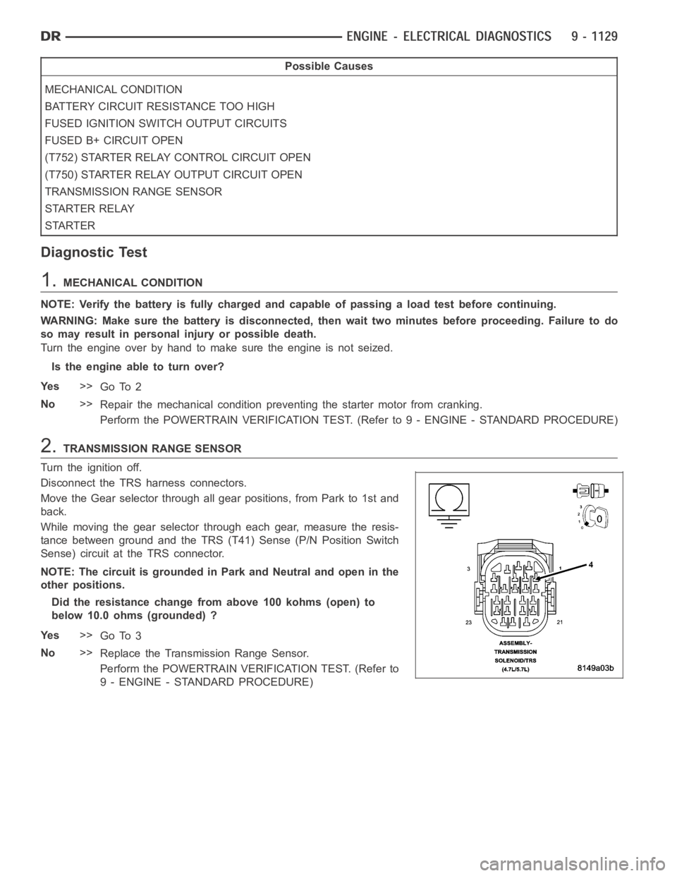
2.TRANSMISSION RANGE SENSOR
Turn the ignition off.
Disconnect the TRS harness connectors.
Move the Gear selector through all gear positions, from Park to 1st and
back.
While moving the gear selector through each gear, measure the resis-
tance between ground and the TRS (T41) Sense (P/N Position Switch
Sense) circuit at the TRS connector.
NOTE: The circuit is grounded in Park and Neutral and open in the
other positions.
Did the resistance change from above 100 kohms (open) to
below 10.0 ohms (grounded) ?
Ye s>>
Go To 3
No>>
Replace the Transmission Range Sensor.
Perform the POWERTRAIN VERIFICATION TEST. (Refer to
9 - ENGINE - STANDARD PROCEDURE)
Page 439 of 5267
3.EXCESSIVE RESISTANCE IN THE BATTERY CIRCUIT
Turn the ignition off.
Check the Battery Cables for excessive resistance using the service information procedure.
Did either Battery Cable have a voltage drop greater than 0.2 of a volt?
Ye s>>
Repair the excessive resistance in the Battery circuit.
Perform the POWERTRAIN VERIFICATION TEST. (Refer to 9 - ENGINE - STANDARD PROCEDURE)
No>>
Go To 4
4.STARTER RELAY
Turn ignition off.
Remove the Starter Relay from IPM.
CAUTION: The Parking Brake must be on and the Transmission must be in park for a vehicle equipped with
an automatic transmission.
WARNING: When the engine is operating, do not stand in direct line with the fan. Do not put your hands
near the pulleys, belts, or fan. Do notwear loose clothing. Failure to follow these instructions can result in
personal injury or death.
Briefly connect a jumper wire from the Internal Fused B+ circuit to the (T750) Starter Relay Output circuit.
Did the Starter Motor crank the engine?
Ye s>>
Go To 5
No>>
Go To 7
5.(T751) FUSED IGNITION SWITCH OUTPUT CIRCUIT
Ignition on, engine not running.
Using a 12-volt test light, probe the (T751) Fused Ignition Switch Output circuit in the Starter Relay connector.
While observing 12-volt test light, hold ignition key in the start position.
Does the test light illuminate brightly?
Ye s>>
Go To 6
No>>
Repair the excessive resistance in the(T751)FusedIgnitionSwitchOutput circuit. Inspect related fuses
and repair as necessary.
Perform the POWERTRAIN VERIFICATION TEST. (Refer to 9 - ENGINE - STANDARD PROCEDURE)
Page 444 of 5267
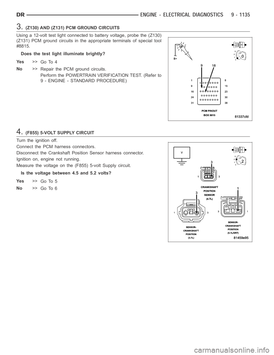
3.(Z130) AND (Z131) PCM GROUND CIRCUITS
Using a 12-volt test light connected to battery voltage, probe the (Z130)
(Z131) PCM ground circuits in the appropriate terminals of special tool
#8815.
Does the test light illuminate brightly?
Ye s>>
Go To 4
No>>
Repair the PCM ground circuits.
Perform the POWERTRAIN VERIFICATION TEST. (Refer to
9 - ENGINE - STANDARD PROCEDURE)
4.(F855) 5-VOLT SUPPLY CIRCUIT
Turn the ignition off.
Connect the PCM harness connectors.
Disconnect the Crankshaft Position Sensor harness connector.
Ignition on, engine not running.
Measure the voltage on the (F855) 5-volt Supply circuit.
Is the voltage between 4.5 and 5.2 volts?
Ye s>>
Go To 5
No>>
Go To 6
Page 453 of 5267
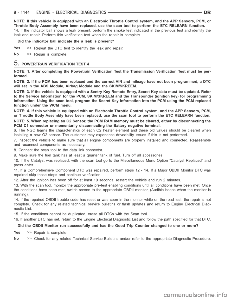
NOTE: If this vehicle is equipped with an Electronic Throttle Control system, and the APP Sensors, PCM, or
Throttle Body Assembly have been replaced, use the scan tool to perform theETC RELEARN function.
14. If the indicator ball shows a leak present, perform the smoke test indicated in the previous test and identify the
leak and repair. Perform this verification test when the repair is complete.
Didtheindicatorballindicatethealeakispresent?
Ye s>>
Repeat the DTC test to identify the leak and repair.
No>>
Repair is complete.
5.POWERTRAIN VERIFICATION TEST 4
NOTE: 1. After completing the Powertrain Verification Test the Transmission Verification Test must be per-
formed.
NOTE: 2. If the PCM has been replaced and the correct VIN and mileage have notbeen programmed, a DTC
will set in the ABS Module, Airbag Module and the SKIM/SKREEM.
NOTE: 3. If the vehicle is equipped with a Sentry Key Remote Entry, Secret Key data must be updated. Refer
to the Service Information for the PCM, SKIM/SKREEM and the Transponder (ignition key) for programming
information. Using the scan tool, program the Secret Key information intothe PCM using the PCM replaced
function under the WCM menu.
NOTE: 4. If this vehicle is equipped with an Electronic Throttle Control system, and the APP Sensors, PCM,
or Throttle Body Assembly have been replaced, use the scan tool to perform the ETC RELEARN function.
NOTE: 5. When replacing an O2 Sensor, the PCM RAM memory must be cleared, either by disconnecting the
PCM C1 connector or momentarily disconnecting the Battery negative terminal.
6. The NGC learns the characteristics of each O2 heater element and these old values should be cleared when
installing a new O2 sensor. The customermay experience driveability issues if this is not performed.
7. Inspect the vehicle to make sure that all engine components are properlyinstalled and connected. Reassemble
and reconnect components as necessary.
8. Connect the scan tool to the data link connector.
9. Make sure the fuel tank has at least a quarter tank of fuel. Turn off all accessories.
10. If the Catalyst was replaced, with the scan tool go to the MiscellaneousMenu Option
Catalyst Replacedand
press enter.
11. If a Comprehensive Component DTC was repaired, perform steps 12 - 14. Ifa Major OBDII Monitor DTC was
repaired skip those steps and continue verification.
12. After the ignition has been off for at least 10 seconds, restart the vehicle and run 2 minutes.
13. With the scan tool, monitor the appropriate pre-test enabling conditions until all conditions have been met. Once
the conditions have been met, switch screen to the appropriate OBDII monitor, (Audible beeps when the monitor is
running).
14. If the repaired OBDII trouble code has reset or was seen in the monitor while on the road test, the repair is not
complete. Check for any related technical service bulletins or flash updates and return to Engine Electrical Diag-
nostic List.
15. If the conditions cannot be duplicated, erase all DTCs with the Scan tool.
16. If another DTC has set, return to the Engine Electrical Diagnostic Listand follow the path specified for that DTC.
Did the OBDII Monitor run successfully and has the Good Trip Counter changed to one or more?
Ye s>>
Repair is complete.
No>>
Check for any related Technical Service Bulletins and/or refer to the appropriate Diagnostic Procedure.
Page 456 of 5267
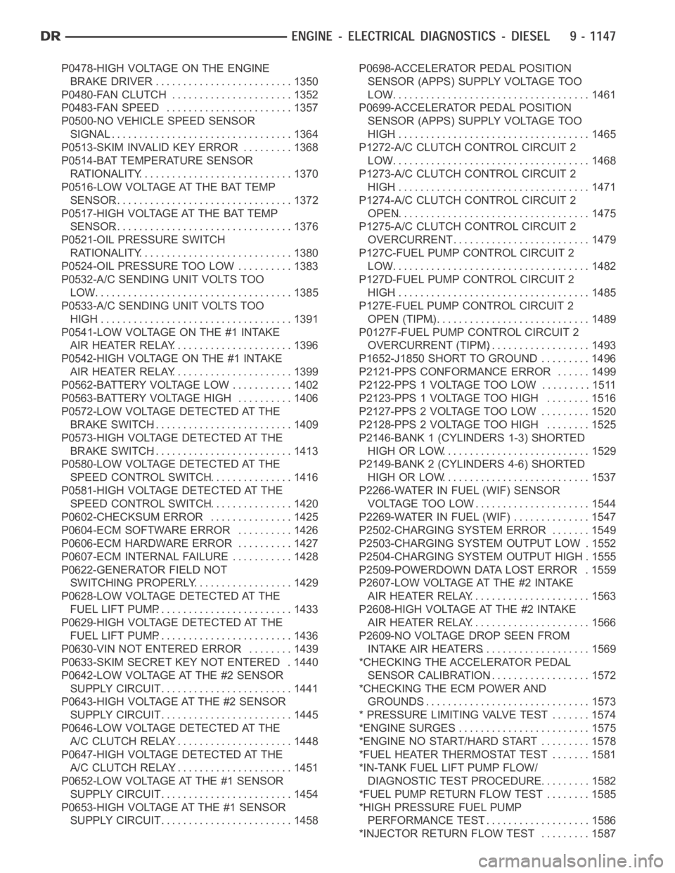
P0478-HIGH VOLTAGE ON THE ENGINE
BRAKE DRIVER.......................... 1350
P0480-FAN CLUTCH ...................... 1352
P0483-FAN SPEED ....................... 1357
P0500-NO VEHICLE SPEED SENSOR
SIGNAL.................................. 1364
P0513-SKIM INVALID KEY ERROR ......... 1368
P0514-BAT TEMPERATURE SENSOR
RATIONALITY............................ 1370
P0516-LOW VOLTAGE AT THE BAT TEMP
SENSOR................................. 1372
P0517-HIGH VOLTAGE AT THE BAT TEMP
SENSOR................................. 1376
P0521-OIL PRESSURE SWITCH
RATIONALITY............................ 1380
P0524-OIL PRESSURE TOO LOW .......... 1383
P0532-A/C SENDING UNIT VOLTS TOO
LOW..................................... 1385
P0533-A/C SENDING UNIT VOLTS TOO
HIGH.................................... 1391
P0541-LOW VOLTAGE ON THE #1 INTAKE
AIR HEATER RELAY...................... 1396
P0542-HIGH VOLTAGE ON THE #1 INTAKE
AIR HEATER RELAY...................... 1399
P0562-BATTERY VOLTAGE LOW ........... 1402
P0563-BATTERY VOLTAGE HIGH .......... 1406
P0572-LOW VOLTAGE DETECTED AT THE
BRAKE SWITCH.......................... 1409
P0573-HIGH VOLTAGE DETECTED AT THE
BRAKE SWITCH.......................... 1413
P0580-LOW VOLTAGE DETECTED AT THE
SPEED CONTROL SWITCH................ 1416
P0581-HIGH VOLTAGE DETECTED AT THE
SPEED CONTROL SWITCH................ 1420
P0602-CHECKSUM ERROR ............... 1425
P0604-ECM SOFTWARE ERROR .......... 1426
P0606-ECM HARDWARE ERROR .......... 1427
P0607-ECM INTERNAL FAILURE ........... 1428
P0622-GENERATOR FIELD NOT
SWITCHING PROPERLY.................. 1429
P0628-LOW VOLTAGE DETECTED AT THE
FUEL LIFT PUMP......................... 1433
P0629-HIGH VOLTAGE DETECTED AT THE
FUEL LIFT PUMP......................... 1436
P0630-VIN NOT ENTERED ERROR ........ 1439
P0633-SKIM SECRET KEY NOT ENTERED . 1440
P0642-LOW VOLTAGE AT THE #2 SENSOR
SUPPLY CIRCUIT......................... 1441
P0643-HIGH VOLTAGE AT THE #2 SENSOR
SUPPLY CIRCUIT......................... 1445
P0646-LOW VOLTAGE DETECTED AT THE
A/C CLUTCH RELAY...................... 1448
P0647-HIGH VOLTAGE DETECTED AT THE
A/C CLUTCH RELAY...................... 1451
P0652-LOW VOLTAGE AT THE #1 SENSOR
SUPPLY CIRCUIT......................... 1454
P0653-HIGH VOLTAGE AT THE #1 SENSOR
SUPPLY CIRCUIT......................... 1458P0698-ACCELERATOR PEDAL POSITION
SENSOR (APPS) SUPPLY VOLTAGE TOO
LOW..................................... 1461
P0699-ACCELERATOR PEDAL POSITION
SENSOR (APPS) SUPPLY VOLTAGE TOO
HIGH.................................... 1465
P1272-A/C CLUTCH CONTROL CIRCUIT 2
LOW..................................... 1468
P1273-A/C CLUTCH CONTROL CIRCUIT 2
HIGH.................................... 1471
P1274-A/C CLUTCH CONTROL CIRCUIT 2
OPEN.................................... 1475
P1275-A/C CLUTCH CONTROL CIRCUIT 2
OVERCURRENT.......................... 1479
P127C-FUEL PUMP CONTROL CIRCUIT 2
LOW..................................... 1482
P127D-FUEL PUMP CONTROL CIRCUIT 2
HIGH.................................... 1485
P127E-FUEL PUMP CONTROL CIRCUIT 2
OPEN (TIPM)............................. 1489
P0127F-FUEL PUMP CONTROL CIRCUIT 2
OVERCURRENT (TIPM)
................... 1493
P1652-J1850 SHORT TO GROUND ......... 1496
P2121-PPS CONFORMANCE ERROR ...... 1499
P2122-PPS 1 VOLTAGE TOO LOW ......... 1511
P2123-PPS 1 VOLTAGE TOO HIGH ........ 1516
P2127-PPS 2 VOLTAGE TOO LOW ......... 1520
P2128-PPS 2 VOLTAGE TOO HIGH ........ 1525
P2146-BANK 1 (CYLINDERS 1-3) SHORTED
HIGH OR LOW........................... 1529
P2149-BANK 2 (CYLINDERS 4-6) SHORTED
HIGH OR LOW........................... 1537
P2266-WATER IN FUEL (WIF) SENSOR
VOLTAGE TOO LOW...................... 1544
P2269-WATER IN FUEL (WIF) .............. 1547
P2502-CHARGING SYSTEM ERROR ....... 1549
P2503-CHARGING SYSTEM OUTPUT LOW . 1552
P2504-CHARGING SYSTEM OUTPUT HIGH . 1555
P2509-POWERDOWN DATA LOST ERROR . 1559
P2607-LOW VOLTAGE AT THE #2 INTAKE
AIR HEATER RELAY...................... 1563
P2608-HIGH VOLTAGE AT THE #2 INTAKE
AIR HEATER RELAY...................... 1566
P2609-NO VOLTAGE DROP SEEN FROM
INTAKE AIR HEATERS.................... 1569
*CHECKING THE ACCELERATOR PEDAL
SENSOR CALIBRATION................... 1572
*CHECKING THE ECM POWER AND
GROUNDS............................... 1573
* PRESSURE LIMITING VALVE TEST ....... 1574
*ENGINE SURGES ........................ 1575
*ENGINE NO START/HARD START ......... 1578
*FUEL HEATER THERMOSTAT TEST ....... 1581
*IN-TANK FUEL LIFT PUMP FLOW/
DIAGNOSTIC TEST PROCEDURE.......... 1582
*FUEL PUMP RETURN FLOW TEST ........ 1585
*HIGH PRESSURE FUEL PUMP
PERFORMANCE TEST.................... 1586
*INJECTOR RETURN FLOW TEST ......... 1587
Page 461 of 5267

POWERTRAIN VERIFICATION TEST VER - 1 (DIESEL)
Diagnostic Test
1.POWERTRAIN VERIFICATION TEST VER - 1 (DIESEL)
1. Clear the DTC before continuing.
2. Check if any of the following conditions exist.
3. The ECM has been disconnected or replaced.
4. The battery power has been disconnected.
5. If the ECM has been replaced, do the following:
6. For ABS and Airbag Systems: Action: Enter correct VIN and Mileage in ECM.Erase ABS and Airbag Module
codes.
NOTE: 7. If the Engine Control Module has been replaced and the correct VIN and mileage have not been
programmed, a DTC will be set in the ABS, Airbag Modules and SKIM module.
8. If the ECM has not been replaced, do the following.
9. Inspect the vehicles to ensure that all engine components are connected. Reassemble and reconnect compo-
nents as necessary.
10. Attempt to start the engine.
11. If the engine is unable to start, look for any Technical Service Bulletins that may relate to this condition. Return
to Symptom list if necessary.
12. If the there are no DTCs present and all components are functional, the repair is complete.
Are any DTC(s) present?
Ye s>>
Repair is not complete, refer to appropriate symptom.
No>>
Repair is complete.
Page 462 of 5267
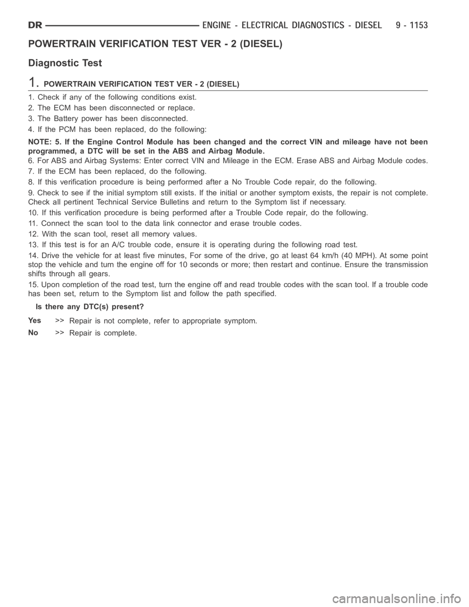
POWERTRAIN VERIFICATION TEST VER - 2 (DIESEL)
Diagnostic Test
1.POWERTRAIN VERIFICATION TEST VER - 2 (DIESEL)
1. Check if any of the following conditions exist.
2. The ECM has been disconnected or replace.
3. The Battery power has been disconnected.
4. If the PCM has been replaced, do the following:
NOTE: 5. If the Engine Control Module has been changed and the correct VIN and mileage have not been
programmed, a DTC will be set in the ABS and Airbag Module.
6. For ABS and Airbag Systems: Enter correct VIN and Mileage in the ECM. Erase ABS and Airbag Module codes.
7. If the ECM has been replaced, do the following.
8. If this verification procedure is being performed after a No Trouble Code repair, do the following.
9. Check to see if the initial symptom still exists. If the initial or another symptom exists, the repair is not complete.
Check all pertinent Technical Service Bulletins and return to the Symptomlist if necessary.
10. If this verification procedure is being performed after a Trouble Coderepair, do the following.
11. Connect the scan tool to the data link connector and erase trouble codes.
12. With the scan tool, reset all memory values.
13. If this test is for an A/C trouble code, ensure it is operating during thefollowing road test.
14. Drive the vehicle for at least five minutes, For some of the drive, go at least 64 km/h (40 MPH). At some point
stop the vehicle and turn the engine off for 10 seconds or more; then restartand continue. Ensure the transmission
shifts through all gears.
15. Upon completion of the road test, turn the engine off and read trouble codeswiththescantool.Ifatroublecode
has been set, return to the Symptom list and follow the path specified.
Is there any DTC(s) present?
Ye s>>
Repair is not complete, refer to appropriate symptom.
No>>
Repair is complete.
Page 463 of 5267
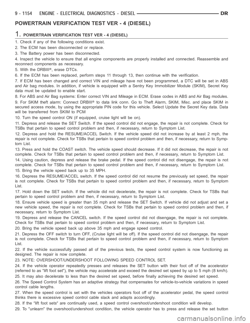
POWERTRAIN VERIFICATION TEST VER - 4 (DIESEL)
1.POWERTRAIN VERIFICATION TEST VER - 4 (DIESEL)
1. Check if any of the following conditions exist.
2. The ECM has been disconnected or replace.
3. The Battery power has been disconnected.
4. Inspect the vehicle to ensure that all engine components are properly installed and connected. Reassemble and
reconnect components as necessary.
5. With the DRBIII
,eraseDTCs.
6. If the ECM has been replaced, perform steps 11 through 13, then continue with the verification.
7. If ECM has been changed and correct VIN and mileage have not been programmed, a DTC will be set in ABS
and Air bag modules. In addition, if vehicle is equipped with a Sentry Key Immobilizer Module (SKIM), Secret Key
data must be updated to enable start.
8. For ABS and Air Bag systems: Enter correct VIN and Mileage in ECM. Erase codes in ABS and Air Bag modules.
9. For SKIM theft alarm: Connect DRBIII
to data link conn. Go to Theft Alarm, SKIM, Misc. and place SKIM in
secured access mode, by using the appropriate PIN code for this vehicle. Select Update the Secret Key data. Data
will be transferred from SKIM to PCM
10. Turn the speed control ON (if equipped, cruise light will be on).
11. Depress and release the SET Switch. If the speed control did not engage,the repair is not complete. Check for
TSBs that pertain to speed control problem and then, if necessary, return to Symptom List.
12. Depress and hold the RESUME/ACCEL Switch. If the vehicle speed did not increase by at least 2 mph, the
repair is not complete. Check for TSBs that pertain to speed control problem and then, if necessary, return to Symp-
tom List.
13. Press and hold the COAST switch. The vehicle speed should decrease. If it did not decrease, the repair is not
complete. Check for TSBs that pertain to speed control problem and then, ifnecessary, return to Symptom List.
14. Using caution, depress and release the brake pedal. If the speed control did not disengage, the repair is not
complete. Check for TSBs that pertain to speed control problem and then, ifnecessary, return to Symptom List.
15. Bring the vehicle speed back up to 35 MPH.
16. Depress the RESUME/ACCEL switch. If the speed control did not resume the previously set speed, the repair
is not complete. Check for TSBs that pertain to speed control problem and then, if necessary, return to Symptom
List.
17. Hold down the SET switch. If the vehicle did not decelerate, the repair is not complete. Check for TSBs that
pertain to speed control problem and then, if necessary, return to SymptomList.
18. Ensure vehicle speed is greater than 35 mph and release the SET Switch. If vehicle did not adjust and set a
new vehicle speed, the repair is not complete. Check for TSBs that pertain to speed control problem and then, if
necessary, return to Symptom List.
19. Depress and release the CANCEL switch. If the speed control did not disengage, the repair is not complete.
Check for TSBs that pertain to speed control problem and then, if necessary, return to Symptom List.
20. Bring the vehicle speed back up above 35 mph and engage speed control.
21. Depress the OFF switch to turn OFF, (Cruise light will be off). If the speed control did not disengage, the repair
is not complete. Check for TSBs that pertain to speed control problem and then, if necessary, return to Symptom
List.
22. If the vehicle successfully passed all of the previous tests, the speedcontrol system is now functioning as
designed. The repair is now complete.
23. NOTE: OVERSHOOT/UNDERSHOOT FOLLOWING SPEED CONTROL SET.
24. If the vehicle operator repeatedly presses and releases the SET buttonwith their foot off of the accelerator
(referred to as
lift foot set), the vehicle may accelerate and exceed the desired set speed by up to 5 mph (8km/h).
25. It may also decelerate to less than the desired set speed, before finally achieving the desired set speed.
26. The Speed Control System has an adaptive strategy that compensates forvehicle-to-vehicle variations in speed
control cable lengths.
27. When the speed control is set with the vehicles operators foot off of theaccelerator pedal, the speed control
thinks there is excessive speed control cable slack and adapts accordingly.
28. If the
lift foot setsare continually used, a speed control overshoot/undershoot condition will develop.
29. To
unlearnthe overshoot/undershoot condition, the vehicle operator has to press and release the set button
Page 465 of 5267
POWERTRAIN VERIFICATION TEST VER - 5 (DIESEL)
Diagnostic Test
1.POWERTRAIN VERIFICATION TEST VER - 5 (DIESEL)
1. Check if any of the following conditions exist.
2. The ECM has been disconnected or replace.
3. The Battery power has been disconnected.
4. Inspect the vehicle to ensure that all engine components are properly installed and connected. Reassemble and
reconnect components as necessary.
5. If any existing diagnostic trouble codes have not been repaired, go to Symptom List and follow path specified.
6. Connect the scan tool to the data link connector.
7. Ensure the fuel tank has at least a quarter tank of fuel. Turn off all accessories.
8. Perform steps 15 through 17 if the PCM has been replaced. Then proceed with the verification. If the ECM has
not been replaced skip those steps and continue verification.
9. If ECM has been changed and correct VIN and mileage have not been programmed, a DTC will be set in ABS
and Air bag modules. In addition, if vehicle is equipped with a Sentry Key Immobilizer Module (SKIM), Secret Key
data must be updated to enable start.
10. For ABS and Air Bag systems: Enter correct VIN and Mileage in ECM. Erase codes in ABS and Air Bag mod-
ules.
11. For SKIM theft alarm: Connect scan tool to data link connector to Theft Alarm, SKIM, Misc. and place SKIM in
secured access mode by using appropriate PIN code for this vehicle. SelectUpdate the Secret Key data. Data will
be transferred from SKIM to PCM.
12. If a Comprehensive Component DTC was repaired, perform steps 10-13. Ifa Major OBDII Monitor DTC was
repaired skip those steps and continue verification.
13. After the ignition has been off for at least 10 seconds, restart the vehicle and run 2 minutes.
14. If there are no new DTC’s, the repair was successful and is now complete.Erase DTC’s and disconnect the
scan tool.
15. If the repaired DTC has reset, the repair is not complete. Check for any related TSB’s or flash updates and
return to the Symptom list.
16. If another DTC has set, return to the Symptom List and follow the path specified for that DTC.
17. With the scan tool, monitor the appropriate pre-test enabling conditions until all conditions have been met. Once
the conditions have been met, switch screen to the appropriate OBDII monitor, (Audible beeps when the monitor is
running).
18. If the monitor ran, the repair was successful and is now complete. EraseDTC’s and disconnect the scan tool.
19. If the repaired OBDII trouble code has reset or was seen in the monitor while on the road test, the repair is not
complete. Check for any related technical service bulletins or flash updates and return to Symptom List.
20. If another DTC has set, return to the Symptom List and follow the path specified for that DTC.
Is any DTC(s) present?
Ye s>>
Repair is not complete, refer to appropriate symptom.
No>>
Repair is complete.