sensor DODGE RAM SRT-10 2006 Service Repair Manual
[x] Cancel search | Manufacturer: DODGE, Model Year: 2006, Model line: RAM SRT-10, Model: DODGE RAM SRT-10 2006Pages: 5267, PDF Size: 68.7 MB
Page 311 of 5267
Inspect the coolant system for proper level and condition.
Is the coolant level and condition OK?
Ye s>>
Go To 3
No>>
Inspect the vehicle for a coolant leak and add the necessary amount of coolant.
Perform the POWERTRAIN VERIFICATION TEST. (Refer to 9 - ENGINE - STANDARD PROCEDURE)
3.THERMOSTAT
NOTE: This test works best if performed on a cold engine (cold soak).
Ignition on, engine not running.
With a scan tool, read the Eng Coolant Tmp Deg value. If the engine was allowed to sit overnight (cold soak), the
temperature value should be a sensible value that is somewhere close to theambient temperature.
NOTE: If engine coolant temperature is above 82°C (180°F), allow the engine to cool until 65°C (150°F) is
reached.
Start the Engine.
During engine warm-up monitor the Eng Coolant Tmp Deg value. The temp deg value change should be a smooth
transition from start up to normal operating temp 82°C (180°F). Also monitor the actual coolant temperature with a
thermometer.
NOTE: As the engine warms up to operating temperature, the actual coolant temperature (thermometer read-
ing) and the Eng Coolant Tmp Deg on the scan tool should stay relatively closetoeachother.
Using the appropriate service information, determine the proper openingtemperature of the thermostat.
Did the thermostat open at the proper temperature?
Ye s>>
Go To 4
No>>
Replace the thermostat.
Perform the POWERTRAIN VERIFICATION TEST. (Refer to 9 - ENGINE - STANDARD PROCEDURE)
4.ECT SENSOR
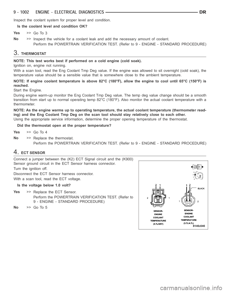
Connect a jumper between the (K2) ECT Signal circuit and the (K900)
Sensor ground circuit in the ECT Sensor harness connector.
Turn the ignition off.
Disconnect the ECT Sensor harness connector.
With a scan tool, read the ECT voltage.
Is the voltage below 1.0 volt?
Ye s>>
Replace the ECT Sensor.
Perform the POWERTRAIN VERIFICATION TEST. (Refer to
9 - ENGINE - STANDARD PROCEDURE)
No>>
Go To 5
Page 312 of 5267
5.(K2) ECT SIGNAL CIRCUIT SHORTED TO BATTERY VOLTAGE
Turn the ignition off.
Disconnect the C2 PCM harness connector.
Ignition on, engine not running.
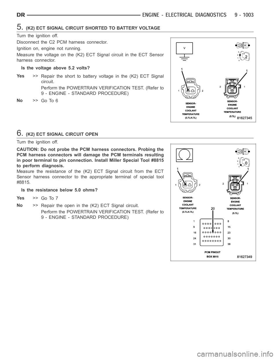
Measure the voltage on the (K2) ECT Signal circuit in the ECT Sensor
harness connector.
Is the voltage above 5.2 volts?
Ye s>>
Repair the short to battery voltage in the (K2) ECT Signal
circuit.
Perform the POWERTRAIN VERIFICATION TEST. (Refer to
9 - ENGINE - STANDARD PROCEDURE)
No>>
Go To 6
6.(K2) ECT SIGNAL CIRCUIT OPEN
Turn the ignition off.
CAUTION: Do not probe the PCM harness connectors. Probing the
PCM harness connectors will damage the PCM terminals resulting
in poor terminal to pin connection. Install Miller Special Tool #8815
to perform diagnosis.
Measure the resistance of the (K2) ECT Signal circuit from the ECT
Sensor harness connector to the appropriate terminal of special tool
#8815.
Is the resistance below 5.0 ohms?
Ye s>>
Go To 7
No>>
Repair the open in the (K2) ECT Signal circuit.
Perform the POWERTRAIN VERIFICATION TEST. (Refer to
9 - ENGINE - STANDARD PROCEDURE)
Page 313 of 5267
7.(K900) SENSOR GROUND CIRCUIT OPEN
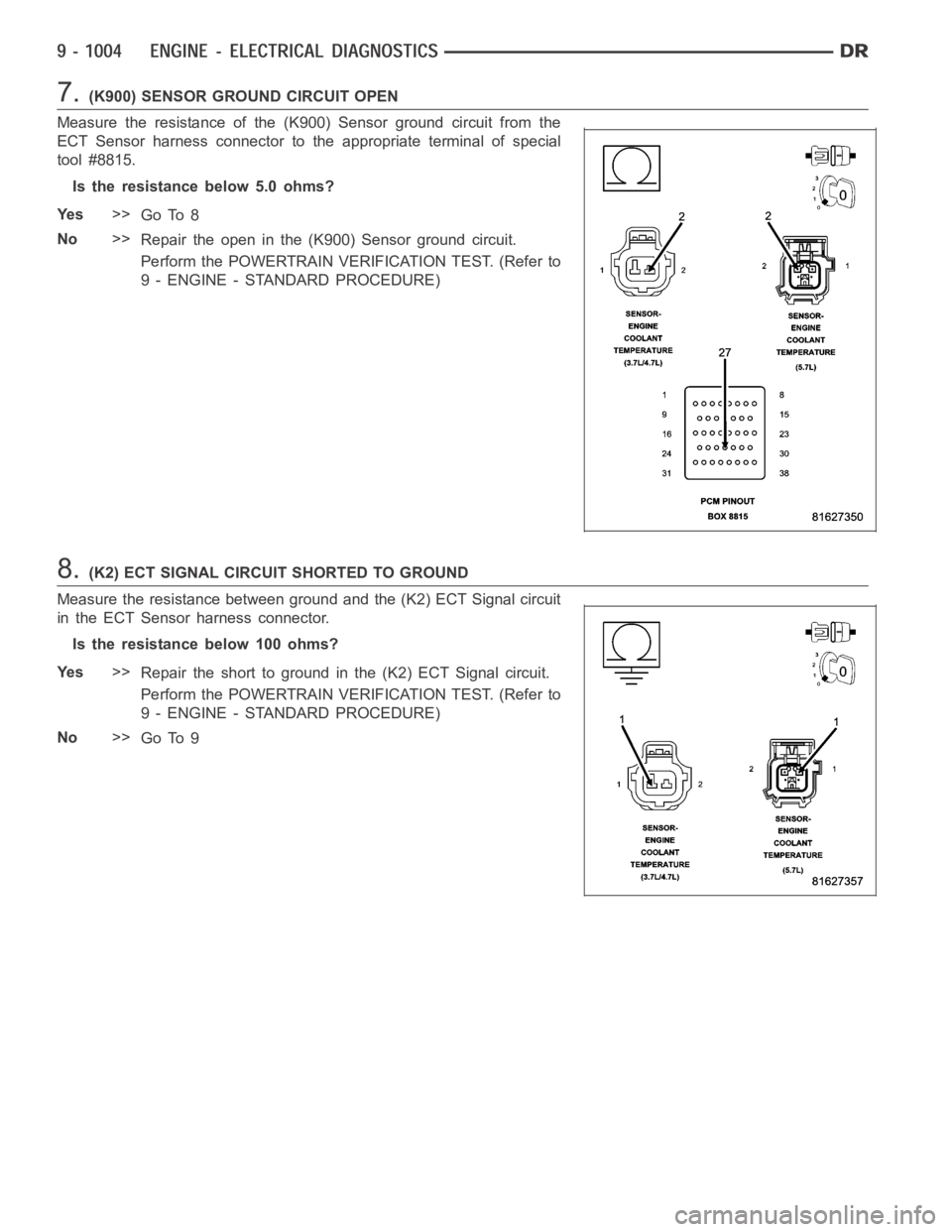
Measure the resistance of the (K900) Sensor ground circuit from the
ECT Sensor harness connector to the appropriate terminal of special
tool #8815.
Is the resistance below 5.0 ohms?
Ye s>>
Go To 8
No>>
Repair the open in the (K900) Sensor ground circuit.
Perform the POWERTRAIN VERIFICATION TEST. (Refer to
9 - ENGINE - STANDARD PROCEDURE)
8.(K2) ECT SIGNAL CIRCUIT SHORTED TO GROUND
Measure the resistance between ground and the (K2) ECT Signal circuit
in the ECT Sensor harness connector.
Istheresistancebelow100ohms?
Ye s>>
Repair the short to ground in the (K2) ECT Signal circuit.
Perform the POWERTRAIN VERIFICATION TEST. (Refer to
9 - ENGINE - STANDARD PROCEDURE)
No>>
Go To 9
Page 314 of 5267
9.(K2) ECT SIGNAL CIRCUIT SHORTED TO THE (K900) SENSOR GROUND CIRCUIT
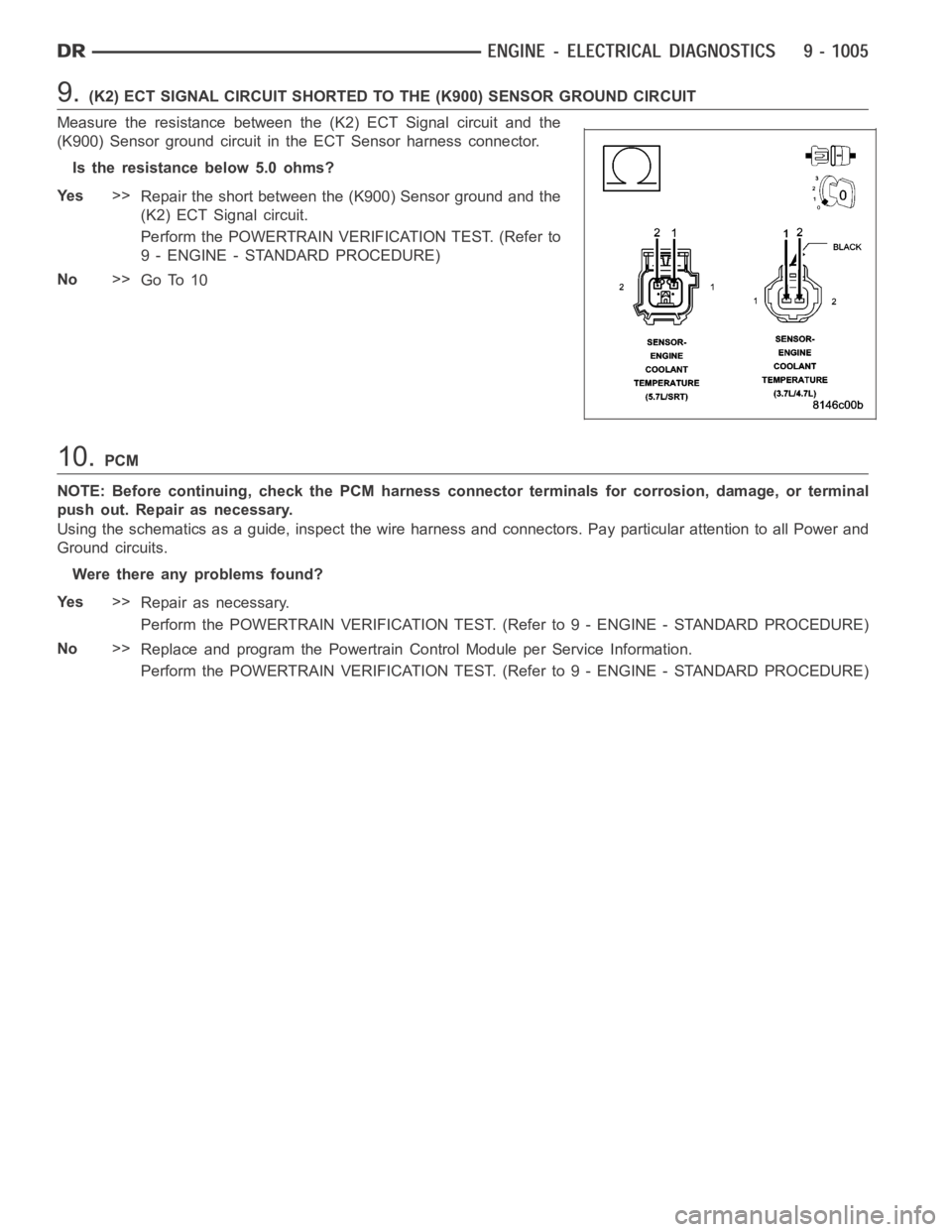
Measure the resistance between the (K2) ECT Signal circuit and the
(K900) Sensor ground circuit in the ECT Sensor harness connector.
Is the resistance below 5.0 ohms?
Ye s>>
Repair the short between the (K900) Sensor ground and the
(K2) ECT Signal circuit.
Perform the POWERTRAIN VERIFICATION TEST. (Refer to
9 - ENGINE - STANDARD PROCEDURE)
No>>
Go To 10
10.PCM
NOTE: Before continuing, check the PCM harness connector terminals for corrosion, damage, or terminal
push out. Repair as necessary.
Using the schematics as a guide, inspect the wire harness and connectors. Pay particular attention to all Power and
Ground circuits.
Were there any problems found?
Ye s>>
Repair as necessary.
Perform the POWERTRAIN VERIFICATION TEST. (Refer to 9 - ENGINE - STANDARD PROCEDURE)
No>>
Replace and program the Powertrain Control Module per Service Information.
Perform the POWERTRAIN VERIFICATION TEST. (Refer to 9 - ENGINE - STANDARD PROCEDURE)
Page 316 of 5267
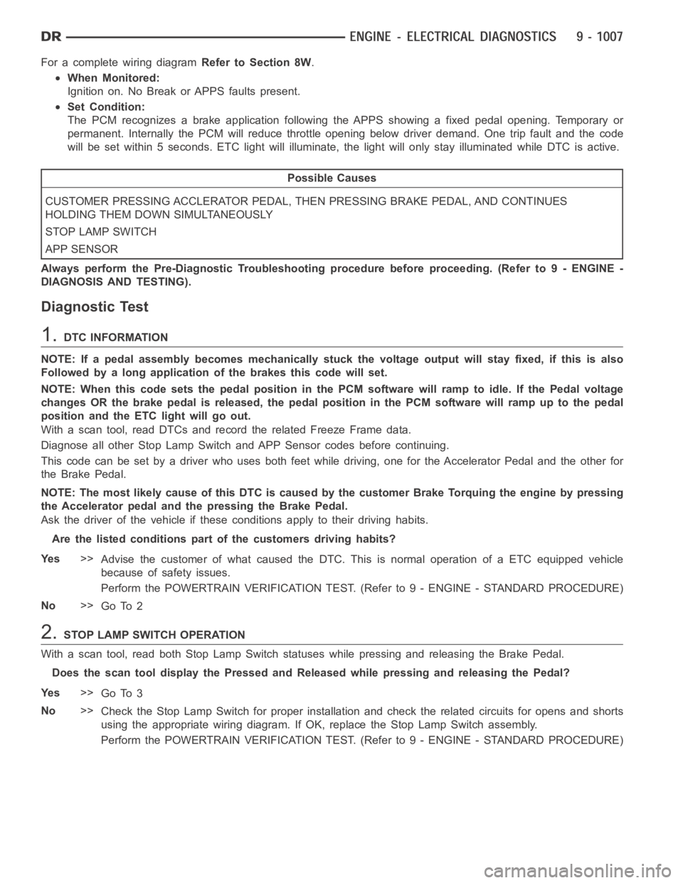
For a complete wiring diagramRefer to Section 8W.
When Monitored:
Ignition on. No Break or APPS faults present.
Set Condition:
The PCM recognizes a brake application following the APPS showing a fixed pedal opening. Temporary or
permanent. Internally the PCM will reduce throttle opening below driver demand. One trip fault and the code
will be set within 5 seconds. ETC light will illuminate, the light will onlystay illuminated while DTC is active.
Possible Causes
CUSTOMER PRESSING ACCLERATOR PEDAL, THEN PRESSING BRAKE PEDAL, AND CONTINUES
HOLDING THEM DOWN SIMULTANEOUSLY
STOP LAMP SWITCH
APP SENSOR
Always perform the Pre-Diagnostic Troubleshooting procedure before proceeding. (Refer to 9 - ENGINE -
DIAGNOSIS AND TESTING).
Diagnostic Test
1.DTC INFORMATION
NOTE: If a pedal assembly becomes mechanically stuck the voltage output will stay fixed, if this is also
Followed by a long application of the brakes this code will set.
NOTE: When this code sets the pedal position in the PCM software will ramp toidle. If the Pedal voltage
changes OR the brake pedal is released, the pedal position in the PCM software will ramp up to the pedal
position and the ETC light will go out.
With a scan tool, read DTCs and record the related Freeze Frame data.
Diagnose all other Stop Lamp Switch and APP Sensor codes before continuing.
This code can be set by a driver who uses both feet while driving, one for the Accelerator Pedal and the other for
the Brake Pedal.
NOTE: The most likely cause of this DTC is caused by the customer Brake Torquing the engine by pressing
the Accelerator pedal and the pressing the Brake Pedal.
Ask the driver of the vehicle if these conditions apply to their driving habits.
Are the listed conditions part of the customers driving habits?
Ye s>>
Advise the customer of what caused the DTC. This is normal operation of a ETCequipped vehicle
because of safety issues.
Perform the POWERTRAIN VERIFICATION TEST. (Refer to 9 - ENGINE - STANDARD PROCEDURE)
No>>
Go To 2
2.STOP LAMP SWITCH OPERATION
With a scan tool, read both Stop Lamp Switch statuses while pressing and releasing the Brake Pedal.
Does the scan tool display the Pressed and Released while pressing and releasing the Pedal?
Ye s>>
Go To 3
No>>
Check the Stop Lamp Switch for proper installation and check the related circuits for opens and shorts
using the appropriate wiring diagram. If OK, replace the Stop Lamp Switch assembly.
Perform the POWERTRAIN VERIFICATION TEST. (Refer to 9 - ENGINE - STANDARD PROCEDURE)
Page 317 of 5267
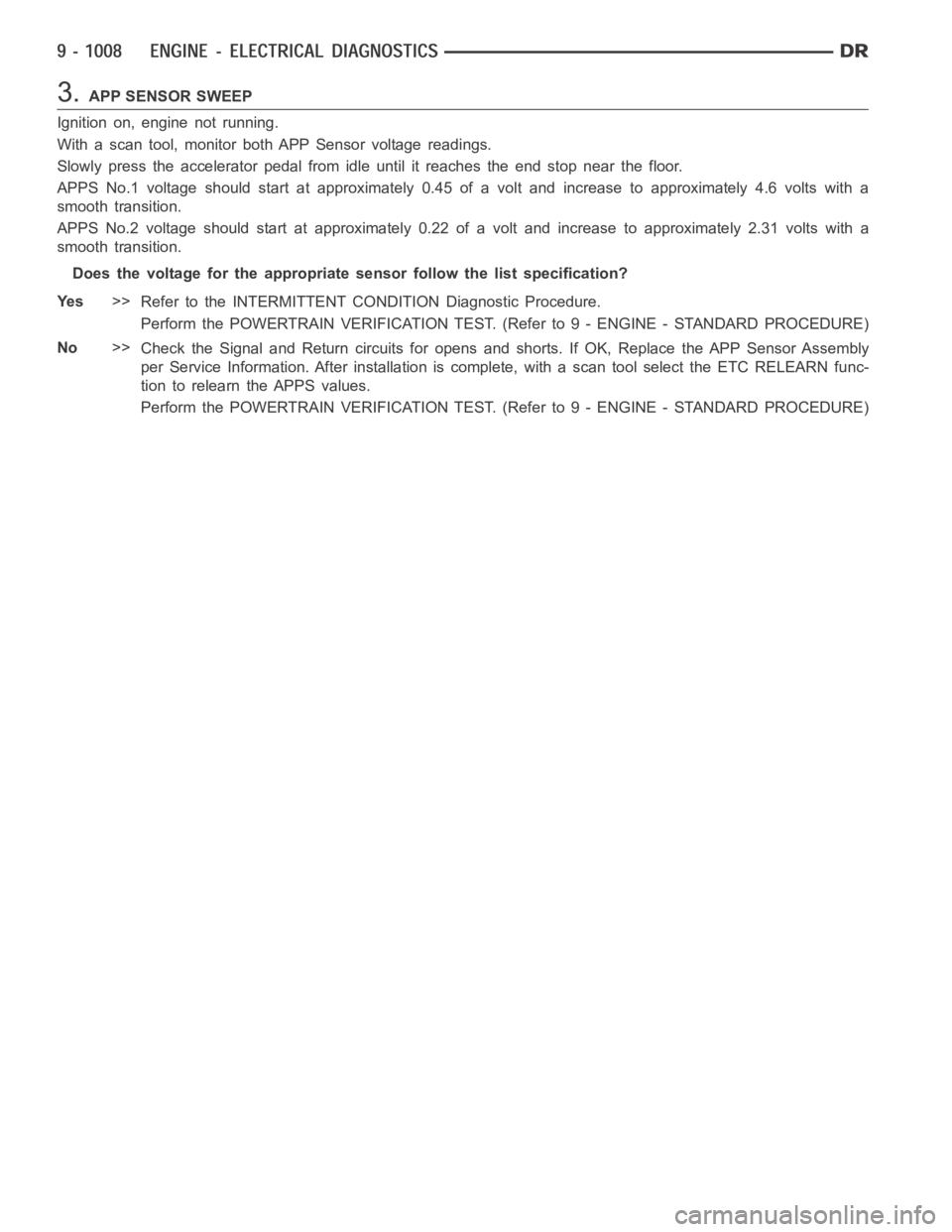
3.APP SENSOR SWEEP
Ignition on, engine not running.
With a scan tool, monitor both APP Sensor voltage readings.
Slowly press the accelerator pedal from idle until it reaches the end stop near the floor.
APPS No.1 voltage should start at approximately 0.45 of a volt and increaseto approximately 4.6 volts with a
smooth transition.
APPS No.2 voltage should start at approximately 0.22 of a volt and increaseto approximately 2.31 volts with a
smooth transition.
Does the voltage for the appropriate sensor follow the list specification?
Ye s>>
Refer to the INTERMITTENT CONDITION Diagnostic Procedure.
Perform the POWERTRAIN VERIFICATION TEST. (Refer to 9 - ENGINE - STANDARD PROCEDURE)
No>>
Check the Signal and Return circuits for opens and shorts. If OK, Replace the APP Sensor Assembly
per Service Information. After installation is complete, with a scan toolselect the ETC RELEARN func-
tion to relearn the APPS values.
Perform the POWERTRAIN VERIFICATION TEST. (Refer to 9 - ENGINE - STANDARD PROCEDURE)
Page 356 of 5267
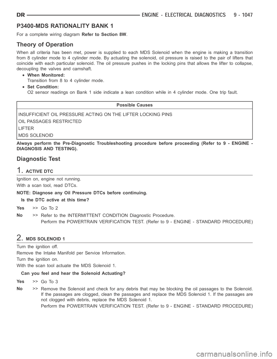
P3400-MDS RATIONALITY BANK 1
For a complete wiring diagramRefer to Section 8W.
Theory of Operation
When all criteria has been met, power is supplied to each MDS Solenoid when the engine is making a transition
from 8 cylinder mode to 4 cylinder mode. By actuating the solenoid, oil pressure is raised to the pair of lifters that
coincide with each particular solenoid. The oil pressure pushes in the locking pins that allows the lifter to collapse,
decoupling the valves and camshaft.
When Monitored:
Transition from 8 to 4 cylinder mode.
Set Condition:
O2 sensor readings on Bank 1 side indicate a lean condition while in 4 cylinder mode. One trip fault.
Possible Causes
INSUFFICIENT OIL PRESSURE ACTING ON THE LIFTER LOCKING PINS
OIL PASSAGES RESTRICTED
LIFTER
MDS SOLENOID
Always perform the Pre-Diagnostic Troubleshooting procedure before proceeding (Refer to 9 - ENGINE -
DIAGNOSIS AND TESTING).
Diagnostic Test
1.ACTIVE DTC
Ignition on, engine not running.
With a scan tool, read DTCs.
NOTE: Diagnose any Oil Pressure DTCs before continuing.
Is the DTC active at this time?
Ye s>>
Go To 2
No>>
Refer to the INTERMITTENT CONDITION Diagnostic Procedure.
Perform the POWERTRAIN VERIFICATION TEST. (Refer to 9 - ENGINE - STANDARD PROCEDURE)
2.MDS SOLENOID 1
Turn the ignition off.
Remove the Intake Manifold per Service Information.
Turn the ignition on.
With the scan tool actuate the MDS Solenoid 1.
Can you feel and hear the Solenoid Actuating?
Ye s>>
Go To 3
No>>
Remove the Solenoid and check for any debris that may be blocking the oil passages to the Solenoid.
If the passages are clogged, clean the passages and replace the MDS Solenoid1.Ifthepassagesare
not clogged with debris, replace the MDS Solenoid 1.
Perform the POWERTRAIN VERIFICATION TEST. (Refer to 9 - ENGINE - STANDARD PROCEDURE)
Page 391 of 5267
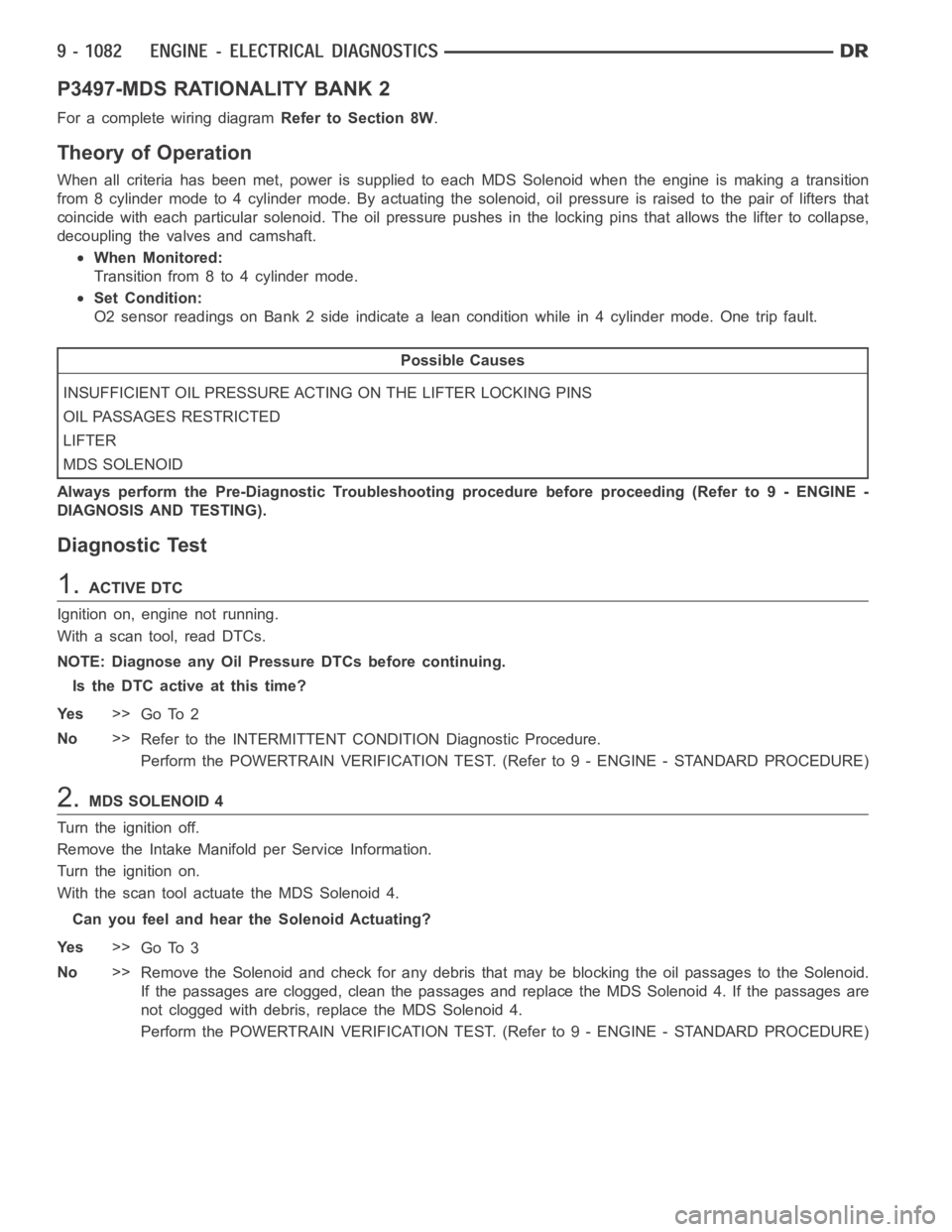
P3497-MDS RATIONALITY BANK 2
For a complete wiring diagramRefer to Section 8W.
Theory of Operation
When all criteria has been met, power is supplied to each MDS Solenoid when the engine is making a transition
from 8 cylinder mode to 4 cylinder mode. By actuating the solenoid, oil pressure is raised to the pair of lifters that
coincide with each particular solenoid. The oil pressure pushes in the locking pins that allows the lifter to collapse,
decoupling the valves and camshaft.
When Monitored:
Transition from 8 to 4 cylinder mode.
Set Condition:
O2 sensor readings on Bank 2 side indicate a lean condition while in 4 cylinder mode. One trip fault.
Possible Causes
INSUFFICIENT OIL PRESSURE ACTING ON THE LIFTER LOCKING PINS
OIL PASSAGES RESTRICTED
LIFTER
MDS SOLENOID
Always perform the Pre-Diagnostic Troubleshooting procedure before proceeding (Refer to 9 - ENGINE -
DIAGNOSIS AND TESTING).
Diagnostic Test
1.ACTIVE DTC
Ignition on, engine not running.
With a scan tool, read DTCs.
NOTE: Diagnose any Oil Pressure DTCs before continuing.
Is the DTC active at this time?
Ye s>>
Go To 2
No>>
Refer to the INTERMITTENT CONDITION Diagnostic Procedure.
Perform the POWERTRAIN VERIFICATION TEST. (Refer to 9 - ENGINE - STANDARD PROCEDURE)
2.MDS SOLENOID 4
Turn the ignition off.
Remove the Intake Manifold per Service Information.
Turn the ignition on.
With the scan tool actuate the MDS Solenoid 4.
Can you feel and hear the Solenoid Actuating?
Ye s>>
Go To 3
No>>
Remove the Solenoid and check for any debris that may be blocking the oil passages to the Solenoid.
If the passages are clogged, clean the passages and replace the MDS Solenoid4.Ifthepassagesare
not clogged with debris, replace the MDS Solenoid 4.
Perform the POWERTRAIN VERIFICATION TEST. (Refer to 9 - ENGINE - STANDARD PROCEDURE)
Page 407 of 5267
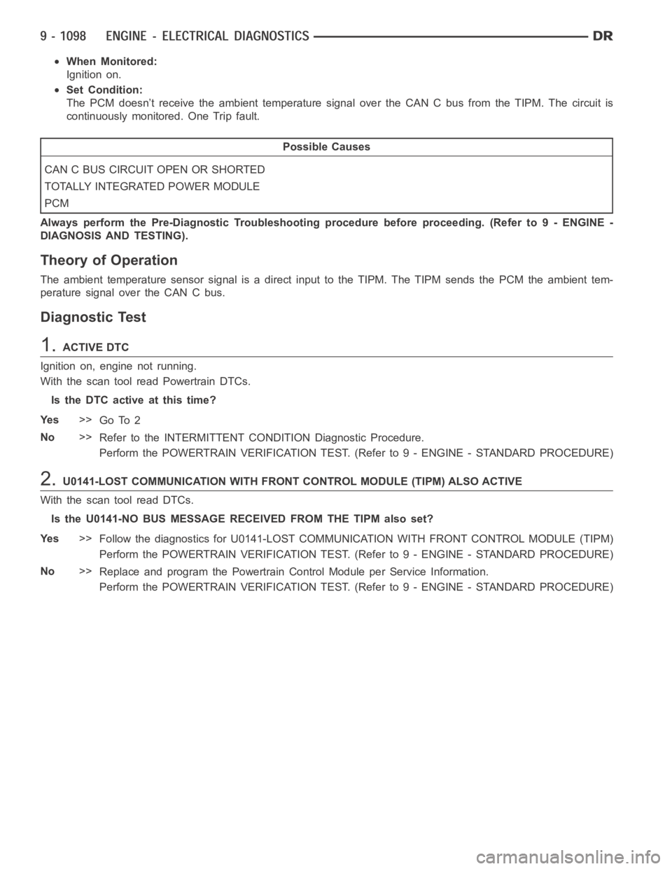
When Monitored:
Ignition on.
Set Condition:
The PCM doesn’t receive the ambient temperature signal over the CAN C bus from the TIPM. The circuit is
continuously monitored. One Trip fault.
Possible Causes
CAN C BUS CIRCUIT OPEN OR SHORTED
TOTALLY INTEGRATED POWER MODULE
PCM
Always perform the Pre-Diagnostic Troubleshooting procedure before proceeding. (Refer to 9 - ENGINE -
DIAGNOSIS AND TESTING).
Theory of Operation
The ambient temperature sensor signal is a direct input to the TIPM. The TIPM sends the PCM the ambient tem-
perature signal over the CAN C bus.
Diagnostic Test
1.ACTIVE DTC
Ignition on, engine not running.
With the scan tool read Powertrain DTCs.
Is the DTC active at this time?
Ye s>>
Go To 2
No>>
Refer to the INTERMITTENT CONDITION Diagnostic Procedure.
Perform the POWERTRAIN VERIFICATION TEST. (Refer to 9 - ENGINE - STANDARD PROCEDURE)
2.U0141-LOST COMMUNICATION WITH FRONT CONTROL MODULE (TIPM) ALSO ACTIVE
With the scan tool read DTCs.
Is the U0141-NO BUS MESSAGE RECEIVED FROM THE TIPM also set?
Ye s>>
Follow the diagnostics for U0141-LOST COMMUNICATION WITH FRONT CONTROL MODULE (TIPM)
Perform the POWERTRAIN VERIFICATION TEST. (Refer to 9 - ENGINE - STANDARD PROCEDURE)
No>>
Replace and program the Powertrain Control Module per Service Information.
Perform the POWERTRAIN VERIFICATION TEST. (Refer to 9 - ENGINE - STANDARD PROCEDURE)
Page 420 of 5267
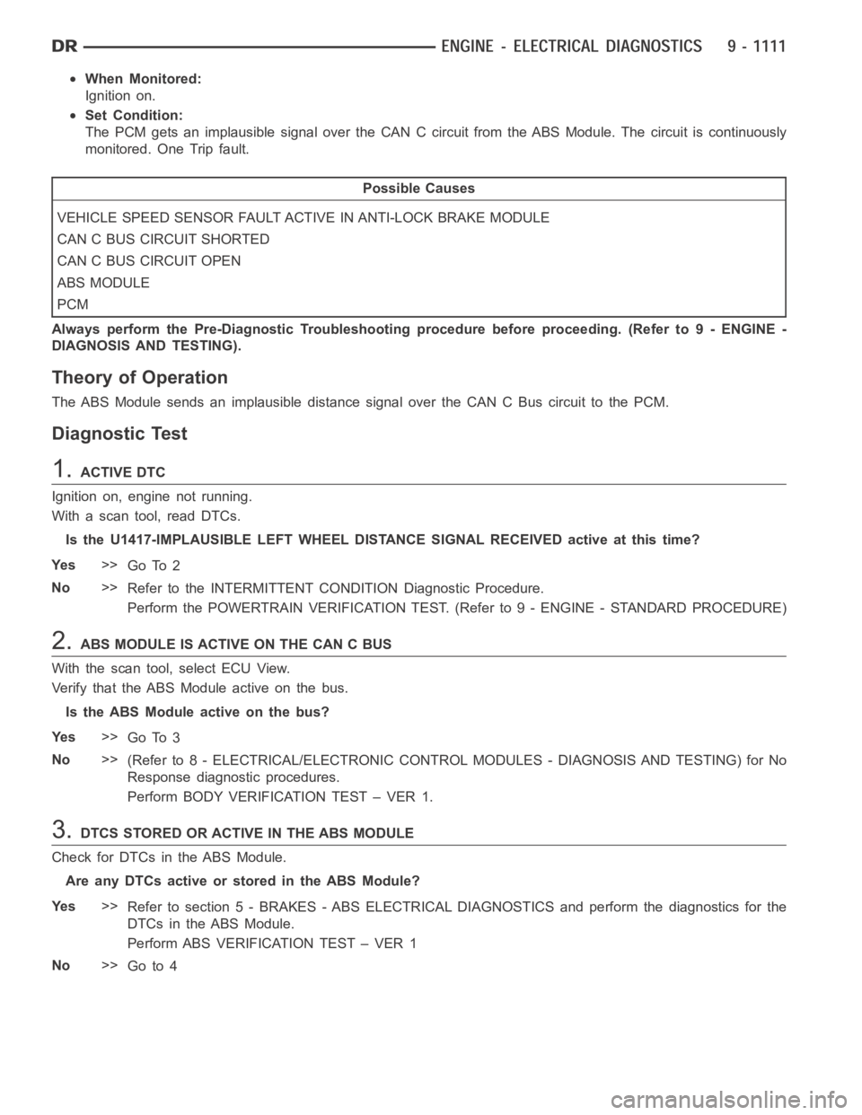
When Monitored:
Ignition on.
Set Condition:
The PCM gets an implausible signal over the CAN C circuit from the ABS Module. The circuit is continuously
monitored. One Trip fault.
Possible Causes
VEHICLE SPEED SENSOR FAULT ACTIVE IN ANTI-LOCK BRAKE MODULE
CAN C BUS CIRCUIT SHORTED
CAN C BUS CIRCUIT OPEN
ABS MODULE
PCM
Always perform the Pre-Diagnostic Troubleshooting procedure before proceeding. (Refer to 9 - ENGINE -
DIAGNOSIS AND TESTING).
Theory of Operation
The ABS Module sends an implausible distance signal over the CAN C Bus circuit to the PCM.
Diagnostic Test
1.ACTIVE DTC
Ignition on, engine not running.
With a scan tool, read DTCs.
Is the U1417-IMPLAUSIBLE LEFT WHEEL DISTANCE SIGNAL RECEIVED active at this time?
Ye s>>
Go To 2
No>>
Refer to the INTERMITTENT CONDITION Diagnostic Procedure.
Perform the POWERTRAIN VERIFICATION TEST. (Refer to 9 - ENGINE - STANDARD PROCEDURE)
2.ABS MODULE IS ACTIVE ON THE CAN C BUS
With the scan tool, select ECU View.
Verify that the ABS Module active on the bus.
Is the ABS Module active on the bus?
Ye s>>
Go To 3
No>>
(Refer to 8 - ELECTRICAL/ELECTRONIC CONTROL MODULES - DIAGNOSIS AND TESTING) for No
Response diagnostic procedures.
Perform BODY VERIFICATION TEST – VER 1.
3.DTCS STORED OR ACTIVE IN THE ABS MODULE
Check for DTCs in the ABS Module.
Are any DTCs active or stored in the ABS Module?
Ye s>>
Refer to section 5 - BRAKES - ABS ELECTRICAL DIAGNOSTICS and perform the diagnostics for the
DTCs in the ABS Module.
Perform ABS VERIFICATION TEST – VER 1
No>>
Go to 4